
ESP-01 Arduino Guide: AT Commands, Programming and Relay
Connect the ESP-01 (ESP8266) to Arduino: 8 pins, 3.3 V power, Wi-Fi with AT commands, flashing with GPIO0 to GND, the ESP-01S relay module and common errors.
The ESP-01 is a tiny (24.8 × 14.3 mm), very cheap module built around the ESP8266 Wi-Fi chip. By connecting the ESP-01 to an Arduino you can add Wi-Fi to a board without wireless, such as an Uno or Nano, with just a few wires. The module ships with AT command firmware: the Arduino sends short text commands like "AT+CWJAP" over serial, and the ESP-01 joins the network, sends and receives data. If you prefer, you can also program the ESP-01 as a standalone microcontroller without any Arduino at all; its processor is far faster than the Uno's.
In this guide you'll learn the ESP-01's 8 pins, why it absolutely needs a strong 3.3 V supply, how to use AT commands with an Arduino Uno, how to build a web page that switches an LED from your phone, how to program the module directly with a USB-TTL adapter (the GPIO0-to-GND method), how to control a lamp with the ESP-01S relay module and how to use it with a Raspberry Pi Pico. At the end you'll find fixes for the most common errors and when a NodeMCU or an ESP32 is the better choice.
What is the ESP-01 and how does it work?
The ESP-01 is the first and smallest module Ai-Thinker designed around the ESP8266EX chip. The board carries the chip, a 26 MHz crystal, the flash memory that stores the program and settings, and a meandering PCB antenna; there's no USB port, voltage regulator or button. That's why the ESP-01 can't be plugged straight into a computer: you have to provide the power and the serial connection yourself. You can use the module in two ways: as a Wi-Fi modem (the AT firmware is installed and the Arduino sends commands) or as a standalone microcontroller (you upload your own program from the Arduino IDE and the AT firmware is erased). Most modules sold today are the black ESP-01S version.
| Feature | Value |
|---|---|
| Chip | ESP8266EX (Tensilica L106, 32-bit) |
| Clock speed | 80 MHz (can be raised to 160 MHz) |
| Flash memory | ESP-01: 512 KB, ESP-01S: 1 MB |
| RAM | About 80 KB of data RAM; ~50 KB left for your program with Wi-Fi connected |
| Wi-Fi | 802.11 b/g/n, 2.4 GHz only, PCB antenna |
| Operating voltage | 3.0–3.6 V (3.3 V recommended) |
| Current | 70–80 mA average while connected, ~170 mA when transmitting, peaks above 300 mA |
| Deep sleep current | About 20 µA (chip) |
| Usable GPIO | 4: GPIO0, GPIO2, GPIO1 (TX), GPIO3 (RX) |
| Analog input | None (the ADC pin isn't broken out) |
| Size | 24.8 × 14.3 mm |
| Factory firmware | AT command firmware (usually 115200 baud) |
ESP-01 vs ESP-01S
| Feature | ESP-01 | ESP-01S |
|---|---|---|
| Board color | Usually blue | Black |
| Flash memory | 512 KB (1 MB on later black versions) | 1 MB |
| Power LED | Red, always on | None |
| Blue LED | On the TX (GPIO1) line, blinks when data is sent | On GPIO2, lights up when the pin is LOW |
| Pinout | 8 pins | Same 8 pins, fully compatible |
| Power draw | A few mA more because of the power LED | Lower, better for battery projects |
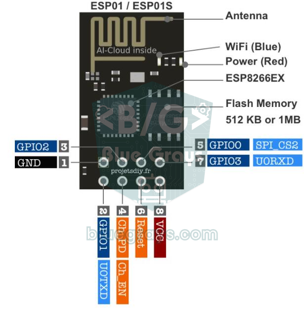
ESP-01 pinout: what the 8 pins do
The ESP-01 has 8 pins in a 2×4 header, and only four of them can be used as inputs and outputs. Not every board has the pin names printed on it, so compare your module with the seller's pinout before wiring it up: swapping VCC and GND kills the module within seconds. Here's what each pin does and how it's connected in normal operation:
| Pin | Function | Connection in normal operation |
|---|---|---|
| VCC | 3.3 V supply input | A strong 3.3 V source (at least 300 mA) |
| GND | Ground | Common GND with the Arduino and the supply |
| TX (GPIO1) | Serial data output | To the Arduino's RX line |
| RX (GPIO3) | Serial data input | To the Arduino's TX line (through a voltage divider on 5 V boards) |
| EN (CH_PD) | Enables the chip | To 3.3 V (directly or through 10 kΩ) |
| RST | Restarts the chip when LOW | Floating or pulled to 3.3 V through 10 kΩ |
| GPIO0 | Selects the boot mode, then general I/O | HIGH (floating) at boot; GND while flashing |
| GPIO2 | General I/O (blue LED on the ESP-01S) | Must stay HIGH at boot |
Current draw: why the Arduino's 3.3 V pin isn't enough
Most problems that kill the ESP-01 or keep it rebooting come from the power supply. While connected to Wi-Fi the module draws 70–80 mA on average and around 170 mA when transmitting; short peaks at boot and while joining the network can exceed 300 mA. The Arduino Uno's 3.3 V pin, however, is officially rated for just 50 mA. An ESP-01 powered from this pin often answers the "AT" command, but the moment it tries to join a network the voltage collapses and the module resets, which looks like a software bug. The fix is an AMS1117-3.3 regulator (1 A) fed from 5 V, plus a 100–470 µF electrolytic capacitor across the module's VCC and GND pins. You'll find how regulators work in the 7805 voltage regulator article.
| Power source | Suitable? | Note |
|---|---|---|
| Arduino Uno 3.3 V pin | No | Officially 50 mA; the module resets while joining Wi-Fi |
| 3.3 V pin of a USB-TTL adapter | Usually not | The chip's internal regulator typically supplies 50–100 mA |
| AMS1117-3.3 regulator (5 V input) | Yes | Up to 1 A; 10 µF on the output, 100–470 µF next to the module |
| ESP-01 USB adapter | Yes | Has a CH340 and an AMS1117; the module plugs straight in |
| 2 × AA batteries (3 V) | Borderline | As the cells drain the voltage drops below 3 V and the module becomes unstable |
| Single-cell Li-ion battery (3.7–4.2 V) | Not directly | Exceeds the 3.6 V limit; needs a low-dropout (LDO) 3.3 V regulator |
Connecting the ESP-01 to an Arduino Uno (for AT commands)
The Arduino Uno's only hardware serial port (D0 and D1) is shared with the USB connection. That's why the most practical approach is to connect the ESP-01 to pins D2 and D3 with the SoftwareSerial library: you don't have to unplug the ESP-01 when uploading to the Uno, and the Serial Monitor stays free for debugging. The Raspberry Pi Pico already runs on 3.3 V, so it doesn't need a divider:
| ESP-01 pin | Arduino Uno | Raspberry Pi Pico | Note |
|---|---|---|---|
| VCC | AMS1117-3.3 output | AMS1117-3.3 or 3V3(OUT) | The Uno's 3.3 V pin isn't enough; the Pico's 3V3 output is recommended up to 300 mA |
| GND | GND | GND | Regulator, board and module share GND |
| TX | D2 | GP1 (UART0 RX) | Connect directly |
| RX | D3 (through a 1 kΩ / 2 kΩ divider) | GP0 (UART0 TX) | No divider needed on the Pico |
| EN (CH_PD) | 3.3 V | 3.3 V | Directly or through 10 kΩ |
| RST | Not connected | Not connected | Optionally pull to 3.3 V through 10 kΩ |
| GPIO0 | Not connected | Not connected | Don't tie it to GND in normal operation |
| GPIO2 | Not connected | Not connected | Must stay HIGH at boot |
To drop the 5 V signal coming from the Uno's D3 pin, connect a 1 kΩ resistor from D3 to the ESP-01's RX and a 2 kΩ resistor from the ESP-01's RX to GND. The output is 5 × 2 / (1 + 2) = 3.33 V; with 2.2 kΩ instead of 2 kΩ you get 3.44 V, and both are safe. You can work out other resistor values with the voltage divider tool. The other direction needs no divider: the 3.3 V from the ESP-01's TX pin is above the 3 V threshold the Uno reads as HIGH. We cover the basics of serial communication in detail in the UART serial communication article.
First test: sending AT commands from the Serial Monitor
- Upload the bridge sketch below to the Uno; for the first try set ESP_BAUD to 115200, because most modules ship at that speed (older ones may use 9600).
- Open the Serial Monitor at 115200 baud and set the line ending to Both NL & CR; without it the module never knows the command has ended.
- Type AT and send it; you should see OK. If you get garbage characters, the speeds don't match.
- SoftwareSerial can't read reliably at 115200, so lower the module's speed permanently to 9600 with AT+UART_DEF=9600,8,1,0,0. Even if the reply looks garbled, the command usually gets through.
- Change ESP_BAUD in the sketch to 9600, upload it again and repeat the AT command; the OK reply should now look clean.
- Check that the module works properly by reading the firmware version with AT+GMR and listing nearby Wi-Fi networks with AT+CWLAP.
1#include <SoftwareSerial.h>
2
3SoftwareSerial esp(2, 3);          // D2 = RX, D3 = TX (bölücüyle ESP RX'e) / D3 to ESP RX via divider
4
5const long ESP_BAUD = 9600;        // ilk denemede 115200 yap / use 115200 on the first try
6
7void setup() {
8  Serial.begin(115200);            // Seri Monitör hızı / Serial Monitor speed
9  esp.begin(ESP_BAUD);
10  Serial.println("AT komutu yaz / type an AT command");
11}
12
13void loop() {
14  if (esp.available()) {           // ESP-01'den geleni ekrana yaz / ESP-01 -> screen
15    Serial.write(esp.read());
16  }
17  if (Serial.available()) {        // klavyeden yazılanı ESP-01'e gönder / keyboard -> ESP-01
18    esp.write(Serial.read());
19  }
20}
The most useful ESP-01 AT commands
| Command | What it does | Example reply |
|---|---|---|
| AT | Tests the connection | OK |
| AT+RST | Restarts the module | OK ... ready |
| AT+GMR | Shows the firmware version | AT version:... SDK version:... OK |
| AT+UART_DEF=9600,8,1,0,0 | Changes the baud rate permanently | OK |
| AT+CWMODE=1 | Station mode; 2 = access point, 3 = both | OK |
| AT+CWLAP | Lists nearby Wi-Fi networks | +CWLAP:(3,"AgAdi",-58,...) |
| AT+CWJAP="AgAdi","Sifre123" | Joins a Wi-Fi network | WIFI CONNECTED, WIFI GOT IP, OK |
| AT+CIFSR | Shows the IP address it received | +CIFSR:STAIP,"192.168.1.45" |
| AT+CIPMUX=1 | Enables multiple connections (required for a server) | OK |
| AT+CIPSERVER=1,80 | Starts a TCP server on port 80 | OK |
| AT+CIPSTART=0,"TCP","192.168.1.10",80 | Connects to a server on link 0 | 0,CONNECT and OK |
| AT+CIPSEND=0,20 | Sends 20 bytes on link 0 | > ... SEND OK |
| AT+CIPCLOSE=0 | Closes link 0 | 0,CLOSED and OK |
Controlling an LED from your phone with an Arduino Uno and ESP-01
Now let's turn the AT commands into a program. The sketch below connects the ESP-01 to your network, opens a small web server on port 80 and prints the IP address to the Serial Monitor. When you type that address into the browser of a phone on the same Wi-Fi, a page with two buttons opens; the buttons switch the built-in LED on pin 13 of the Uno on and off. Connect a relay module instead of the LED and the same method controls a lamp. Before uploading, make sure you've set the module's speed to 9600 in the previous step.
1#include <SoftwareSerial.h>
2
3SoftwareSerial esp(2, 3);              // D2 = RX, D3 = TX (bölücüyle) / D3 via divider
4const int LED_PIN = 13;                // Uno'nun dahili LED'i / Uno onboard LED
5
6const char* WIFI_SSID = "AgAdi";       // Wi-Fi adın / your Wi-Fi name
7const char* WIFI_PASS = "Sifre123";    // Wi-Fi şifren / your Wi-Fi password
8
9bool ledOn = false;
10bool pending = false;                  // cevap bekleyen istek var mı / request waiting for a reply
11int linkId = 0;                        // ESP-01'in bağlantı numarası (0-4) / connection id (0-4)
12char line[64];
13byte lineLen = 0;
14
15// Beklenen yazıyı süre dolana kadar ara / wait until the expected text arrives or time runs out
16bool waitFor(const char* expect, unsigned long timeout) {
17  unsigned long start = millis();
18  size_t idx = 0;
19  size_t len = strlen(expect);
20  while (millis() - start < timeout) {
21    if (esp.available()) {
22      char c = esp.read();
23      Serial.write(c);                 // gelen her şeyi göster / echo everything
24      if (c == expect[idx]) {
25        idx++;
26        if (idx == len) return true;
27      } else {
28        idx = (c == expect[0]) ? 1 : 0;
29      }
30    }
31  }
32  return false;
33}
34
35bool sendAT(const char* cmd, const char* expect, unsigned long timeout) {
36  esp.println(cmd);                    // println sonuna \r\n ekler / println adds \r\n
37  return waitFor(expect, timeout);
38}
39
40void sendPage(int id) {
41  char body[220];
42  snprintf(body, sizeof(body),
43           "<meta name='viewport' content='width=device-width'>"
44           "<h2>LED: %s</h2>"
45           "<a href='/on'><button>AC / ON</button></a> "
46           "<a href='/off'><button>KAPAT / OFF</button></a>",
47           ledOn ? "ACIK / ON" : "KAPALI / OFF");
48  char head[110];
49  snprintf(head, sizeof(head),
50           "HTTP/1.1 200 OK\r\nContent-Type: text/html\r\n"
51           "Content-Length: %d\r\nConnection: close\r\n\r\n",
52           (int)strlen(body));
53
54  esp.print("AT+CIPSEND=");            // önce kaç bayt gideceğini söyle / announce the length first
55  esp.print(id);
56  esp.print(',');
57  esp.println(strlen(head) + strlen(body));
58  if (waitFor(">", 2000)) {            // ">" gelince veriyi yolla / send data after ">"
59    esp.print(head);
60    esp.print(body);
61    waitFor("SEND OK", 5000);
62  }
63  esp.print("AT+CIPCLOSE=");           // bağlantıyı kapat / close the connection
64  esp.println(id);
65  waitFor("OK", 2000);
66}
67
68void handleLine() {
69  if (strncmp(line, "+IPD,", 5) == 0) {          // yeni istek / new request: +IPD,0,384:GET /on ...
70    linkId = line[5] - '0';
71    if (strstr(line, "GET /on ")) ledOn = true;
72    else if (strstr(line, "GET /off ")) ledOn = false;
73    digitalWrite(LED_PIN, ledOn ? HIGH : LOW);
74    pending = true;
75  } else if (pending && lineLen == 0) {           // boş satır = isteğin sonu / empty line = end of request
76    pending = false;
77    sendPage(linkId);
78  }
79}
80
81void setup() {
82  pinMode(LED_PIN, OUTPUT);
83  Serial.begin(115200);
84  esp.begin(9600);                     // AT+UART_DEF=9600,8,1,0,0 ile ayarlanmış olmalı / set with AT+UART_DEF
85
86  sendAT("AT+RST", "ready", 5000);     // temiz başlangıç / clean restart
87  sendAT("AT+CWMODE=1", "OK", 2000);   // istemci modu / station mode
88
89  esp.print("AT+CWJAP=\"");            // AT+CWJAP="ad","şifre" / AT+CWJAP="ssid","password"
90  esp.print(WIFI_SSID);
91  esp.print("\",\"");
92  esp.print(WIFI_PASS);
93  esp.println("\"");
94  if (!waitFor("OK", 20000)) {
95    Serial.println(F("\nWi-Fi baglanamadi / Wi-Fi failed"));
96  }
97
98  sendAT("AT+CIPMUX=1", "OK", 2000);         // sunucu için çoklu bağlantı / multiple connections
99  sendAT("AT+CIPSERVER=1,80", "OK", 2000);   // 80 portunda sunucu / server on port 80
100  sendAT("AT+CIFSR", "OK", 2000);            // IP adresini yaz / print the IP address
101}
102
103void loop() {
104  while (esp.available()) {            // ESP-01'den gelenleri satır satır oku / read line by line
105    char c = esp.read();
106    if (c == '\n') {
107      line[lineLen] = '\0';
108      handleLine();
109      lineLen = 0;
110    } else if (c != '\r' && lineLen < sizeof(line) - 1) {
111      line[lineLen++] = c;
112    }
113  }
114}
Here's how the code works: when a browser connects, the ESP-01 forwards the request to the Arduino as +IPD,0,384:GET /on HTTP/1.1, where 0 is the link number and 384 is the number of bytes received. The Arduino looks for "GET /on" or "GET /off" in that line and sets the LED. When the empty line that marks the end of the request arrives, it announces how many bytes it will send with AT+CIPSEND=0,length, sends the page once the module shows the ">" prompt, and closes the link with AT+CIPCLOSE after the "SEND OK" reply. We kept the page short on purpose: the Uno's 2 KB of RAM isn't enough for long HTML text, and a single CIPSEND can send at most 2048 bytes. For more complex projects, a library such as WiFiEspAT saves you from managing AT commands yourself.
Programming the ESP-01 directly: the GPIO0-to-GND method
The ESP8266 inside the ESP-01, with its 32-bit 80 MHz processor, is much more powerful than an Arduino Uno. If your project only has a relay, a sensor or an LED, you don't need an Arduino at all: you upload the program straight to the ESP-01. When the ESP8266 boots, it checks the levels of GPIO0, GPIO2 and GPIO15 to decide what to do. On the ESP-01 board GPIO15 is already tied to GND and GPIO2 must stay HIGH, so GPIO0 alone selects the boot mode:
| GPIO0 | GPIO2 | GPIO15 | Boot mode | Boot message at 74880 baud |
|---|---|---|---|---|
| HIGH (floating) | HIGH | LOW | Normal run: the program in flash starts | boot mode:(3,x) |
| LOW (GND) | HIGH | LOW | Programming (UART download) mode | boot mode:(1,x) and waiting for host |
| ESP-01 pin | Connection | Note |
|---|---|---|
| VCC | 3.3 V regulator output | The USB-TTL adapter's 3.3 V pin is usually not enough |
| GND | USB-TTL GND and regulator GND | Everything on a common ground |
| TX | USB-TTL RXD | Crossed connection |
| RX | USB-TTL TXD | Jumper must be set to 3.3 V |
| EN (CH_PD) | 3.3 V | Directly or through 10 kΩ |
| RST | Not connected (briefly to GND to reset) | Optionally pull to 3.3 V through 10 kΩ |
| GPIO0 | GND | Only while uploading; disconnect afterwards |
| GPIO2 | Not connected | Must stay HIGH at boot |
- In the Arduino IDE open File > Preferences and add https://arduino.esp8266.com/stable/package_esp8266com_index.json to the "Additional boards manager URLs" field.
- In the Boards Manager, search for esp8266 and install the ESP8266 Community package.
- Choose Generic ESP8266 Module from Tools > Board. Set Flash Size to 1MB (FS:64KB OTA:~470KB) for the ESP-01S, or one of the 512KB options for the old blue ESP-01.
- Set the USB-TTL adapter's jumper to 3.3 V, wire the module according to the table above and keep GPIO0 connected to GND.
- Cut the module's power and reconnect it, or briefly touch RST to GND; the module now boots into programming mode.
- Pick the USB-TTL adapter's port from Tools > Port and upload the sketch. File > Examples > ESP8266 > Blink is a good first test; on the ESP-01S the blue LED is on GPIO2.
- When you see "Hard resetting via RTS pin...", disconnect GPIO0 from GND and restart the module. If GPIO0 stays on GND your program won't run and the module boots into programming mode again.
Relay control with GPIO0 and GPIO2: the ESP-01S relay module
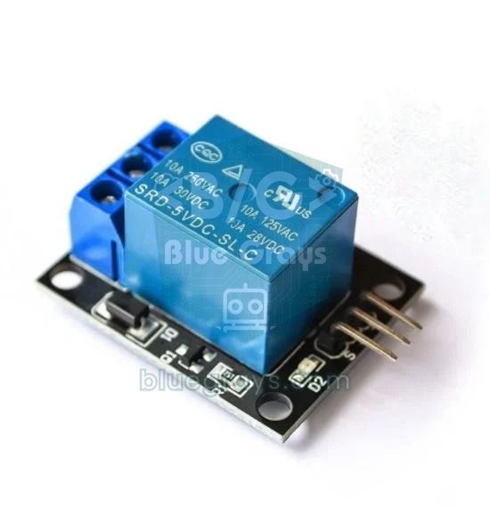
The ESP-01's general-purpose pins are GPIO0 and GPIO2, but both must be HIGH during boot. So whatever you connect to them must not pull the pin LOW while the board starts up. The safest solution is an active-LOW connection: the pin is HIGH at boot so the relay stays off, and when your program drives the pin LOW the relay switches on. The ready-made ESP-01S relay module is designed exactly like this: it runs on 5 V, its on-board regulator makes 3.3 V for the ESP-01S, and GPIO0 drives a relay with 10 A 250 V AC contacts through a transistor. On v4.0 and later boards the relay switches on when GPIO0 is LOW; older v1.0 boards may need a small modification to work with the ESP-01S, so check your board's version.
1#include <ESP8266WiFi.h>
2#include <ESP8266WebServer.h>
3#include <ESP8266mDNS.h>
4
5const char* ssid = "AgAdi";            // Wi-Fi adın / your Wi-Fi name
6const char* password = "Sifre123";     // Wi-Fi şifren / your Wi-Fi password
7
8const int RELAY_PIN = 0;               // ESP-01S röle kartında GPIO0 / GPIO0 on the ESP-01S relay board
9const int RELAY_ON = LOW;              // çoğu kartta LOW = çeker; tersse değiştir / LOW = on, swap if yours is inverted
10const int RELAY_OFF = HIGH;
11
12ESP8266WebServer server(80);
13bool relayOn = false;
14
15void sendPage() {
16  String html = F("<!DOCTYPE html><html><head><meta charset='utf-8'>"
17                  "<meta name='viewport' content='width=device-width,initial-scale=1'>"
18                  "<title>ESP-01</title></head>"
19                  "<body style='font-family:sans-serif;text-align:center'>"
20                  "<h1>ESP-01 Röle / Relay</h1><p><b>");
21  html += relayOn ? "AÇIK / ON" : "KAPALI / OFF";
22  html += F("</b></p><p><a href='/on'><button>AÇ / ON</button></a> "
23            "<a href='/off'><button>KAPAT / OFF</button></a></p></body></html>");
24  server.send(200, "text/html", html);
25}
26
27void setRelay(bool on) {
28  relayOn = on;
29  digitalWrite(RELAY_PIN, on ? RELAY_ON : RELAY_OFF);
30  server.sendHeader("Location", "/");  // ana sayfaya dön / back to the main page
31  server.send(303, "text/plain", "");
32}
33
34void setup() {
35  digitalWrite(RELAY_PIN, RELAY_OFF);  // önce kapalı seviye / off level first
36  pinMode(RELAY_PIN, OUTPUT);
37  Serial.begin(115200);
38
39  WiFi.mode(WIFI_STA);
40  WiFi.begin(ssid, password);
41  while (WiFi.status() != WL_CONNECTED) {
42    delay(500);
43    Serial.print('.');
44  }
45  Serial.println();
46  Serial.println(WiFi.localIP());      // bu adresi tarayıcıda aç / open this address in a browser
47  MDNS.begin("esp01");                 // ya da http://esp01.local / or http://esp01.local
48
49  server.on("/", sendPage);
50  server.on("/on", []() { setRelay(true); });
51  server.on("/off", []() { setRelay(false); });
52  server.begin();
53}
54
55void loop() {
56  server.handleClient();
57  MDNS.update();
58}
After uploading the sketch to the ESP-01S with the method above, plug the module into the relay board and power the board with 5 V. You can read the IP address in the Serial Monitor while the USB-TTL adapter is connected, or find it in your router's list of connected devices; from a computer that supports mDNS, http://esp01.local works too. If you want to add an input such as a button, the best pin is GPIO3 (RX), because its level doesn't matter at boot. In that case use Serial.begin(115200, SERIAL_8N1, SERIAL_TX_ONLY) to open the serial port in transmit-only mode.
ESP-01 with the Raspberry Pi Pico (MicroPython)
You can also add wireless to a Raspberry Pi Pico without Wi-Fi using an ESP-01. Since the Pico runs on 3.3 V, no voltage divider is needed: the ESP-01's RX goes to GP0 (UART0 TX) and its TX goes to GP1 (UART0 RX). The Pico's hardware UART reads 115200 baud with ease, so you don't have to change the module's speed either; if you already lowered it to 9600 in the Uno section, set baudrate to 9600 in the code as well. Run the MicroPython code below with Thonny; the module joins your network, prints its IP address and lists nearby networks every 30 seconds. If you have a Pico W, its built-in Wi-Fi is easier to use; see the Pico W Wi-Fi web server article.
1from machine import UART, Pin
2import time
3
4# GP0 (TX) -> ESP-01 RX, GP1 (RX) <- ESP-01 TX
5uart = UART(0, baudrate=115200, tx=Pin(0), rx=Pin(1))
6
7def at(cmd, timeout=2000):
8    uart.write(cmd + "\r\n")                   # her komut \r\n ile biter / every command ends with \r\n
9    start = time.ticks_ms()
10    resp = b""
11    while time.ticks_diff(time.ticks_ms(), start) < timeout:
12        if uart.any():
13            resp += uart.read()
14            if b"OK" in resp or b"ERROR" in resp or b"FAIL" in resp:
15                break
16    print(cmd, "->", resp)                     # cevabı göster / show the reply
17    return resp
18
19at("ATE0")                                     # komut yankısını kapat / turn off echo
20at("AT")                                       # OK gelmeli / should answer OK
21at("AT+CWMODE=1")                              # istemci modu / station mode
22at('AT+CWJAP="AgAdi","Sifre123"', 20000)       # Wi-Fi'ye bağlan / join Wi-Fi
23at("AT+CIFSR")                                 # IP adresini sor / ask for the IP
24
25while True:
26    at("AT+CWLAP", 10000)                      # çevredeki ağları tara / scan nearby networks
27    time.sleep(30)
ESP-01, NodeMCU or ESP32?
| Feature | ESP-01 | NodeMCU (ESP8266) | ESP32 DevKit |
|---|---|---|---|
| Chip | ESP8266 | ESP8266 | ESP32 (dual-core) |
| Usable GPIO | 4 (two are TX/RX) | About 11 | About 25 |
| Analog input | None | 1 (A0) | 18 channels, 12-bit |
| USB programming | No, needs a USB-TTL adapter | Yes | Yes |
| Power | 3.3 V only | USB 5 V or VIN | USB 5 V or VIN |
| Bluetooth | No | No | Yes (Classic and BLE) |
| Size | 24.8 × 14.3 mm | Breadboard-friendly board | Breadboard-friendly board |
| Best for | Adding Wi-Fi to an Arduino, a single relay or sensor | Getting started with Wi-Fi, a few sensors | Projects with many pins and Bluetooth |
The ESP-01's biggest advantages are its size and price; it's ideal for adding Wi-Fi to an existing Arduino project or making a single relay or sensor wireless. But because it has no USB, swapping wires, adding a regulator and grounding GPIO0 for every upload gets tedious. It has no analog input, and since GPIO16 isn't broken out, timed wake-up from deep sleep doesn't work unless you solder a thin wire to one of the chip's pins. If you're planning a battery-powered project, enter the average current into the battery life calculator to see how many days it will last. If you're still learning or need more than three pins, the NodeMCU ESP8266 gives you the same chip with USB and a regulator. If you need Bluetooth, more pins and more processing power, the ESP32 is the right choice; we compare the boards in Arduino or ESP32?
ESP-01 project ideas
- Wi-Fi smart plug: switch a lamp from your phone with the ESP-01S relay module and the sketch above; add a timer so it turns on automatically in the evening.
- Wireless temperature sensor: connect a DS18B20 sensor to GPIO2; the 4.7 kΩ pull-up on the data line also provides the HIGH level needed at boot.
- Humidity and temperature monitor: show DHT11 readings on a web page you open on your phone.
- Motion alert: connect a PIR sensor to GPIO3 and send a Telegram message when motion is detected; the method is very similar to the ESP32 Telegram bot article.
- Wi-Fi for an Arduino project: send the readings of a weather station built on an Uno to a program on your computer or to a server with AT commands.
- Garage door remote: wire the relay contacts in parallel with the door opener's button and open the door from your phone.
Common mistakes and how to fix them
| Symptom | Likely cause | Fix |
|---|---|---|
| "Failed to connect to ESP8266: Timed out waiting for packet header" | The module isn't in programming mode, or TX and RX are swapped | Tie GPIO0 to GND, power-cycle the module, connect TX to RXD and RX to TXD |
| Garbage characters in the Serial Monitor | Baud rate mismatch; boot messages are at 74880 baud | Try 115200 and 9600; choose 74880 to see the boot message |
| No reply at all to AT | Wrong line ending, TX and RX swapped, or EN not connected | Choose Both NL & CR, cross the lines, connect EN to 3.3 V |
| Module keeps resetting, drops out while joining Wi-Fi | Not enough current | Use a separate AMS1117-3.3 and a 100–470 µF capacitor, shorten the wires |
| "busy p..." reply | A new command was sent before the previous one finished | Wait for OK or ERROR after every command |
| +CWJAP:3 and FAIL | Network not found (5 GHz network or wrong name) | Use a 2.4 GHz network and watch upper and lower case |
| Module gets very hot, LED stays off | 5 V applied to VCC, or VCC and GND reversed | Cut the power immediately; the module is most likely damaged |
| Module won't boot with the relay attached | The circuit on GPIO0 or GPIO2 pulls the pin LOW at boot | Use an active-LOW connection or move the input to GPIO3 |
| 5 V relay module never switches off | A 3.3 V HIGH doesn't fully turn off the 5 V module's optocoupler | Use a 3.3 V-compatible relay module or a transistor driver |
| AT commands stop working after uploading from the Arduino IDE | Your program replaced the AT firmware | Reflash Espressif's AT firmware with esptool or the Flash Download Tool |
Despite its small size, the ESP-01 is a great module for learning all the basic Wi-Fi concepts: IP addresses, TCP connections, web servers and serial communication. If something doesn't work, check the power supply first, then the TX-RX lines and the level on GPIO0; the vast majority of problems come down to these three points. In the BlueGrays app you'll find projects such as Wi-Fi connection, web server, mDNS, over-the-air updates (OTA) and smart relay lighting, with step-by-step circuit diagrams and code.
Frequently asked questions
Can the ESP-01 run on 5V?
No. The ESP-01 runs between 3.0 and 3.6 V, and connecting 5 V to the VCC pin can permanently damage it. If you want to power it from the Arduino's 5 V, put a regulator such as an AMS1117-3.3 in between, and drop the 5 V signal from the Uno's TX line to 3.3 V with a voltage divider.
Can I power the ESP-01 from the Arduino 3.3V pin?
It's not recommended. The Uno's 3.3 V pin is officially rated for 50 mA, while the ESP-01 draws 170 mA when transmitting and over 300 mA in short peaks. Even if the module answers AT commands, it resets while joining the network; use a separate 3.3 V regulator that can supply at least 300–500 mA.
Why is my ESP-01 not responding to AT commands?
The most common causes are a wrong baud rate, the Serial Monitor line ending not set to Both NL & CR, TX and RX not crossed, and the EN (CH_PD) pin not connected to 3.3 V. If a program was uploaded to the module from the Arduino IDE before, the AT firmware has been erased and you need to flash it again.
Does uploading Arduino code erase the ESP-01 AT firmware?
Yes. The program you upload from the Arduino IDE is written to flash in place of the AT firmware, and the module no longer understands AT commands. To go back to AT mode, flash Espressif's ESP8266 AT firmware with esptool or the Flash Download Tool at the addresses that match your module's flash size.
What is the difference between ESP-01 and ESP-01S?
The chip and pinout are the same. The ESP-01S is usually black, has 1 MB of flash, no power LED, and its blue LED is on GPIO2. The old blue ESP-01 has 512 KB of flash, a red power LED that's always on and a blue LED on the TX line.
What is the default baud rate of the ESP-01?
Most modules with current AT firmware ship at 115200 baud; older ones may use 9600 or 57600. The first messages printed at boot, however, are at 74880 baud. If you use SoftwareSerial on an Arduino Uno, lowering the speed permanently to 9600 with AT+UART_DEF=9600,8,1,0,0 makes the link reliable.
Projects to build after reading this
See all projects
ESP32 Wi-Fi STA Connection (with LCD Screen)
In this project, we connect the ESP32 to the home Wi-Fi network in Station (STA) mode in a secure, fault-tolerant manner. We store the SSID and password in a separate secrets.h file to prevent leaking to Git, set up an auto-reconnect mechanism, and display the RSSI signal level and IP address on an I2C LCD screen. The internal LED works as a status indicator. It is a production-grade connection manager.

ESP32 Asynchronous Web Server (with IP Display on LCD)
In this project, we’re turning the ESP32 into an asynchronous web server that you can control from your phone or computer on the same Wi-Fi network. Thanks to the ESPAsyncWebServer library, the server can process multiple requests simultaneously (unlike the classic WebServer.h, which blocks on a single request). You’ll be able to open the ESP32’s IP address in a browser and click the ON/OFF buttons (the /on and /off routes) to turn the LED connected to GPIO 5 on and off.

ESP32 mDNS: Accessing the Device via bluegrays-esp.local (with LCD Screen)
In this project, we add an mDNS (Multicast DNS) service to the ESP32, allowing us to access the device using a human-readable hostname like bluegrays-esp.local instead of an IP address. Even if the IP address assigned by DHCP changes, you can always reach the device using the same name. We also run a small web server on the device to send LED control commands via a browser using the address http://bluegrays-esp.local/. The I2C LCD screen displays the hostname, IP address, and LED status in b

ESP32 OTA Update — Wireless Firmware Installation (With LCD Screen)
In this project, you’ll learn how to upload new firmware to the ESP32 over Wi-Fi without a USB cable. Using the ArduinoOTA library, the ESP32 becomes visible on the network and is automatically listed as bluegrays-ota in the "Network port" tab of the Arduino IDE. The initial upload is done via USB, and all subsequent updates are wireless—a critical feature for field devices. The I2C LCD screen displays the Wi-Fi status, IP address, hostname, OTA upload percentage, and error messages in both

Real-Time Clock from the Internet via ESP32 NTP
The ESP32 connects to Wi-Fi and retrieves real time with millisecond precision from NTP (Network Time Protocol) servers. Thanks to the configTzTime() function, the Turkey time zone (TRT, UTC+3) is automatically applied, and DST transitions in countries that observe daylight saving time are automatically managed using a POSIX TZ string. The time is displayed both on the Serial Monitor and on an optional I2C LCD. configTzTime() starts the SNTP service; periodic resynchronization takes place wh

ESP32 Smart Lighting (PIR + LDR + Relay + OLED)
Turn your hallway, bathroom, or pantry into smart lighting with ESP32! Using a PIR motion sensor, LDR light sensor, and a relay module, we build the classic "light turns on when motion is detected in the dark" scenario — if the environment is already bright, motion does NOT trigger the light, saving energy during the day. The light stays on for 30 seconds; if motion continues, the timer resets and the light stays on longer. The SSD1306 OLED shows large-font status (ON / DAYTIME / WAITING), a cou
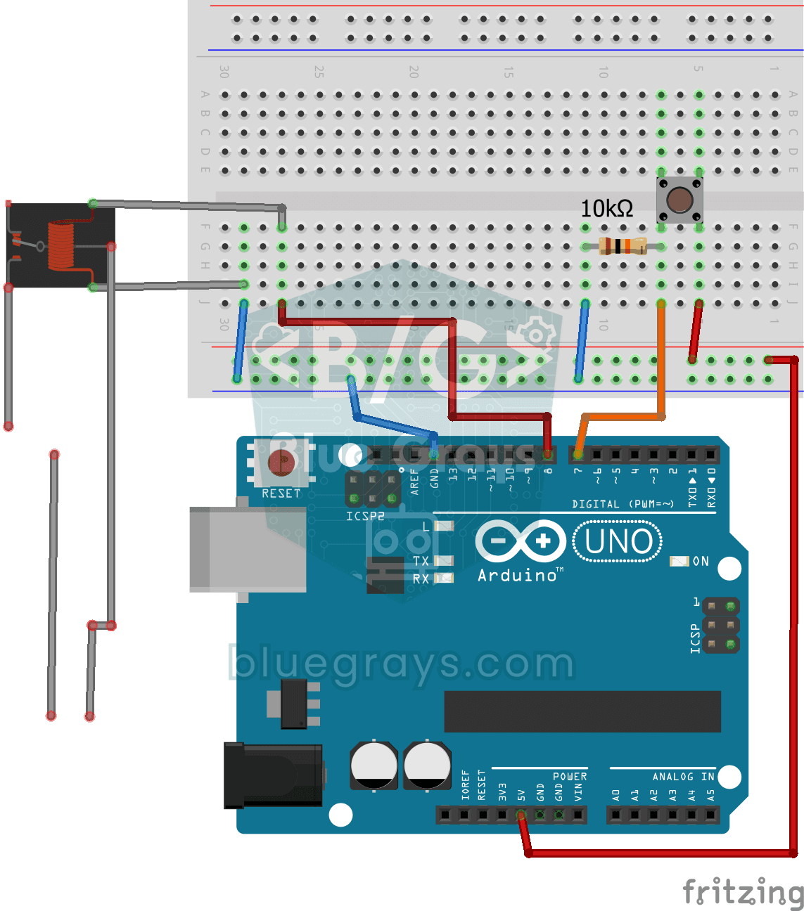
Lighting 220V Bulb with Button (On-Off)
Want to switch a real household bulb on and off with a tiny button? Each time you press the button, the Arduino flips a relay and the bulb lights up; press again and it goes off. The relay is a go-bet
One-Way Communication Between 2 Arduinos
You get two Arduinos talking over a single wire: press the button on one and the LED on the other lights up, press it again and it goes off. The sending board reports the button press with a short mes