
16x2 LCD Arduino Wiring Without I2C: 4-Bit Mode and Contrast
How to wire a 16x2 LCD to Arduino without an I2C module: what the 16 pins do, 4-bit mode, contrast, LiquidCrystal, fixing black boxes and using a 20x4 LCD.
When you wire a 16x2 LCD to an Arduino without an I2C module, you use 12 of the display's 16 pins: six go to Arduino digital pins, and the rest handle power, contrast and the backlight. It sounds crowded, but this connection teaches you how the display really works, spares you any I2C address hunting, is faster than I2C, and doesn't hold up your project when you don't have an I2C backpack. Most LCDs in Arduino starter kits come bare, without the I2C module, too.
In this guide you'll learn the job of each of the 16 pins, why we only use 4 data lines (4-bit mode), how to wire the contrast potentiometer and the commands of the LiquidCrystal library. Then you'll design custom characters for a bar graph that fills with a potentiometer, move up to a 20x4 LCD, and use the same display with an ESP32 and a Raspberry Pi Pico. In the final sections you'll find fixes for the most common problems such as "black boxes" and a "blank screen", and when it makes sense to switch to an I2C module.
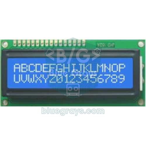
How does a 16x2 LCD work?
The black blob-shaped chip on the back of the display is the HD44780 driver (or an exact clone), the common language of almost all character LCDs. Arduino sends this chip two kinds of bytes: commands (clear the screen, move the cursor here, turn the display on) and characters (the code of the letter to show). The RS pin says which one is being sent: with RS LOW the byte is a command, with RS HIGH it's a character. The E (enable) pin is the "data ready, read it now" signal; after a byte is placed on the data lines, E is pulsed HIGH briefly and the chip reads the byte on the falling edge. Inside the chip there's an 80-character display memory (DDRAM), a font ROM with 208 built-in characters, and a small memory (CGRAM) for the 8 custom characters you'll design.
| Feature | Value |
|---|---|
| Driver chip | HD44780 or compatible (KS0066, SPLC780) |
| Display | 16 columns × 2 rows, each character 5 × 8 pixels |
| Supply | 4.5–5.5 V (special 3.3 V versions also exist) |
| Logic current | About 1–2 mA |
| Backlight current | About 15–30 mA (LED, depending on model) |
| Data bus | 8-bit or 4-bit parallel |
| Custom characters | 8 (CGRAM) |
| Command time | Most commands 37 µs, clear() and home() about 1.5 ms |
What each of the 16 pins does
| Pin | Name | Function | Connection |
|---|---|---|---|
| 1 | VSS | Ground | GND |
| 2 | VDD | Logic supply | 5V |
| 3 | V0 (VO, VEE) | Contrast adjustment | Wiper of a 10 kΩ potentiometer |
| 4 | RS | Command (LOW) or character (HIGH) select | Arduino D12 |
| 5 | RW | Read (HIGH) or write (LOW) | GND (we only write) |
| 6 | E | Data-valid pulse | Arduino D11 |
| 7–10 | D0–D3 | Lower data bits | Left unconnected in 4-bit mode |
| 11 | D4 | Data bit 4 | Arduino D5 |
| 12 | D5 | Data bit 5 | Arduino D4 |
| 13 | D6 | Data bit 6 | Arduino D3 |
| 14 | D7 | Data bit 7 | Arduino D2 |
| 15 | A (LED+) | Backlight anode | 5V through 220 Ω |
| 16 | K (LED−) | Backlight cathode | GND |
4-bit mode: why 4 data lines instead of 8?
The HD44780 can take a byte either in one go over 8 data lines (8-bit mode) or in two halves over lines D4–D7 (4-bit mode). In 4-bit mode the upper half of the byte is sent first, then the lower half, with one pulse on the E pin for each half. That takes twice as long, but in practice you won't notice: writing a character still takes around 50 µs, and refreshing the whole screen takes under 2 ms. In return, four Arduino pins are freed up. The LiquidCrystal library picks 4-bit mode automatically when you give the constructor six pins; leaving D0–D3 unconnected is safe because the chip has internal pull-up resistors on them.
The contrast potentiometer
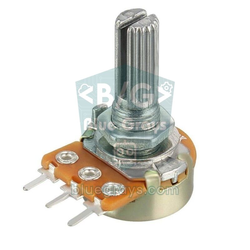
The voltage on the V0 pin decides whether the text is visible at all. What twists the liquid crystal is the difference between VDD and V0; on standard 5 V modules the best image is usually reached with V0 around 0.3–1 V. As V0 approaches 0 V the background of the characters darkens too and empty cells show up as black boxes; as it approaches 5 V the text disappears completely. That's why a potentiometer is the most practical choice for the first setup: connect one outer pin to 5V, the other to GND and the middle pin to V0, then turn it slowly until the text is sharp. Once you've found the setting you can replace the potentiometer with a fixed resistor: 1–2.2 kΩ between V0 and GND works well on most modules.
Step by step: your first text with Arduino
- Solder a 16-pin male header to the LCD and plug the display into the breadboard; on a long breadboard there's room for wires on both sides of the display.
- Bring the Arduino's 5V and GND to the breadboard power rails. Connect LCD pins 1 (VSS) and 16 (K) to GND, pin 2 (VDD) to 5V and pin 15 (A) to 5V through 220 Ω. When you plug the Arduino into USB, the backlight should come on.
- Connect the potentiometer and turn it. Even before uploading any code, 16 black boxes should appear on the top line; that shows the display and contrast are working.
- Connect pin 5 (RW) to GND. Then connect RS to D12, E to D11, and D4–D7 to D5, D4, D3 and D2 respectively.
- Make sure the LiquidCrystal library is installed in the Library Manager (it comes with the Arduino IDE) and upload the code below.
- When the boxes disappear and the text shows up, fine-tune the contrast one last time with the potentiometer.
1// 16x2 LCD, I2C modülü olmadan (4-bit mod) / 16x2 LCD without an I2C module (4-bit mode)
2// RS -> D12, E -> D11, D4 -> D5, D5 -> D4, D6 -> D3, D7 -> D2, RW -> GND, V0 -> pot
3#include <LiquidCrystal.h>
4
5const int RS = 12, EN = 11, D4 = 5, D5 = 4, D6 = 3, D7 = 2;
6LiquidCrystal lcd(RS, EN, D4, D5, D6, D7);
7
8void setup() {
9  lcd.begin(16, 2);              // 16 sütun, 2 satır / 16 columns, 2 rows
10  lcd.print(F("Merhaba Arduino!"));
11  lcd.setCursor(0, 1);           // sütun 0, satır 1 / column 0, row 1
12  lcd.print(F("Sure:"));
13}
14
15void loop() {
16  unsigned long s = millis() / 1000;
17  lcd.setCursor(6, 1);
18  lcd.print(s);
19  lcd.print(F(" sn   "));      // eski haneleri boşlukla sil / overwrite old digits with spaces
20  delay(200);
21}
The code has two small but important habits. First, before writing the changing value, it moves to that position with setCursor() instead of calling clear(), and adds a few spaces after the number. clear() is a heavy command that takes about 1.5 ms, and used in the loop it makes the screen flicker; besides, there's no need to wipe and rewrite the whole screen. The spaces stop an old digit from staying on screen when the number gets shorter (for example from 100 to 99). Second, the fixed texts are written with the F() macro, so they live in program memory instead of RAM. A 16x2 display fits at most 16 characters per line; longer text runs off the right edge and isn't visible.
| Command | What it does |
|---|---|
| lcd.begin(16, 2) | Starts the display and sets the number of columns and rows |
| lcd.print(value) | Prints text, an integer or a decimal; lcd.print(3.14159, 2) prints two decimals |
| lcd.setCursor(column, row) | Chooses where to write; counting starts at 0 |
| lcd.clear() | Clears the screen and homes the cursor (takes 1.5 ms) |
| lcd.cursor() / lcd.noCursor() | Shows or hides the underline cursor |
| lcd.blink() / lcd.noBlink() | Turns the blinking block cursor on or off |
| lcd.display() / lcd.noDisplay() | Turns the image on or off without clearing display memory |
| lcd.scrollDisplayLeft() | Shifts the whole display one column to the left |
| lcd.createChar(num, array) | Loads a custom character into slot 0–7 |
| lcd.write(byte(num)) | Writes a custom character or a ROM code |
Custom characters: a bar graph that fills with a potentiometer
Each character cell is a pixel grid of 5 columns and 8 rows. To define a custom character you write each row as a 5-bit number: 1 means a lit pixel, 0 an unlit one. The HD44780 allows 8 custom characters at a time. The example below uses five of those slots for blocks with 1, 2, 3, 4 and 5 columns filled from the left. With 16 cells × 5 columns you get an 80-step bar that fills and empties smoothly with a potentiometer; ideal for volume, battery level or a sensor percentage. We covered designing custom characters for Turkish letters (ş, ğ, ı, ç) in the I2C LCD article; the same createChar command works exactly the same way over the parallel connection.
1// Özel karakterlerle 80 adımlık çubuk grafik / 80-step bar graph with custom characters
2// Potansiyometre orta ucu -> A0 / potentiometer wiper -> A0
3#include <LiquidCrystal.h>
4
5LiquidCrystal lcd(12, 11, 5, 4, 3, 2);
6
7byte bars[5][8];                       // 1..5 sütun dolu bloklar / blocks with 1..5 columns filled
8
9void buildBars() {
10  for (int n = 0; n < 5; n++) {
11    byte row = 0;
12    for (int c = 0; c <= n; c++) row |= (0b10000 >> c);   // soldan doldur / fill from the left
13    for (int r = 0; r < 8; r++) bars[n][r] = row;
14    lcd.createChar(n, bars[n]);        // karakter 0 = 1 sütun ... 4 = 5 sütun / char 0 = 1 column ... 4 = 5 columns
15  }
16}
17
18void setup() {
19  lcd.begin(16, 2);
20  buildBars();
21  lcd.setCursor(0, 0);                 // createChar sonrası konum ayarla / set position after createChar
22  lcd.print(F("Seviye / Level"));
23}
24
25void loop() {
26  int raw = analogRead(A0);
27  int steps = map(raw, 0, 1023, 0, 80);  // 16 hücre x 5 sütun / 16 cells x 5 columns
28  int percent = map(raw, 0, 1023, 0, 100);
29
30  lcd.setCursor(12, 0);
31  if (percent < 100) lcd.print(' ');
32  if (percent < 10) lcd.print(' ');
33  lcd.print(percent);
34  lcd.print('%');
35
36  lcd.setCursor(0, 1);
37  for (int cell = 0; cell < 16; cell++) {
38    int fill = steps - cell * 5;       // bu hücreye düşen sütun / columns in this cell
39    if (fill >= 5) lcd.write(byte(4));
40    else if (fill > 0) lcd.write(byte(fill - 1));
41    else lcd.print(' ');
42  }
43  delay(50);
44}
The createChar command moves the cursor from display memory into character memory, so after loading custom characters you must call setCursor() before writing, otherwise the first text may not appear. Characters are only stored in CGRAM and are lost when the display loses power, which is why they're loaded again in setup() at every start-up. If you change the definition of a custom character while it's on screen, every cell showing that character changes at once; small animations are made with exactly this trick.
20x4 LCD: same wiring, bigger screen
LCDs with 20 columns and 4 rows use the same HD44780 chip and the same 16 pins; the wiring is identical and in the code you only need lcd.begin(20, 4). Their backlights draw a little more current (40–60 mA), so avoid making the series resistor smaller, to keep the Arduino's 5V rail comfortable during long use. The only quirk you need to know is the row order: in display memory, the end of row 1 continues on row 3, and the end of row 2 continues on row 4. So if you write long text without setCursor(), it overflows from row 1 to row 3, not row 2. Calling setCursor(0, row) at the start of each row removes the problem completely.
1// 20x4 LCD: aynı bağlantı, begin(20, 4) / 20x4 LCD: same wiring, begin(20, 4)
2#include <LiquidCrystal.h>
3
4LiquidCrystal lcd(12, 11, 5, 4, 3, 2);
5
6void setup() {
7  lcd.begin(20, 4);
8  for (int row = 0; row < 4; row++) {
9    lcd.setCursor(0, row);             // her satırı açıkça seç / select every row explicitly
10    lcd.print(F("Satir / Row "));
11    lcd.print(row + 1);
12  }
13}
14
15void loop() {
16  lcd.setCursor(15, 3);
17  lcd.print(millis() / 1000 % 100000);  // 5 haneye sığsın / fit in 5 digits
18  delay(500);
19}
A parallel LCD with the ESP32
A standard 16x2 LCD doesn't give enough contrast unless it's powered from 5 V, while the ESP32's pins are 3.3 V. The good news: as long as RW is tied to GND, the LCD never puts a voltage on the lines; it only listens. Since the lowest input the HD44780 accepts as HIGH at 5 V is around 2.2 V, the ESP32's 3.3 V signals are enough and no level converter is needed. Connect the LCD's VDD to the ESP32 board's VIN pin (5 V from USB). The LiquidCrystal library works on the ESP32 just the same; just avoid pins with a special job at boot, such as GPIO 0, 2, 12 and 15.
1// ESP32 + 16x2 LCD (paralel, 4-bit) / ESP32 + 16x2 LCD (parallel, 4-bit)
2// RS -> GPIO 22, E -> GPIO 21, D4 -> 19, D5 -> 18, D6 -> 26, D7 -> 25
3// VDD -> VIN (5 V), RW -> GND, V0 -> pot, A -> 220 ohm -> VIN
4#include <LiquidCrystal.h>
5
6LiquidCrystal lcd(22, 21, 19, 18, 26, 25);
7
8void setup() {
9  lcd.begin(16, 2);
10  lcd.print("ESP32 + LCD");
11}
12
13void loop() {
14  lcd.setCursor(0, 1);
15  lcd.print("Heap: ");
16  lcd.print(ESP.getFreeHeap() / 1024);   // boş bellek (KB) / free memory (KB)
17  lcd.print(" KB   ");
18  delay(1000);
19}
A parallel LCD with the Raspberry Pi Pico (MicroPython)
The same logic applies to the Raspberry Pi Pico: power the LCD with 5 V from VBUS (pin 40), tie RW to GND and run the signals straight to GP pins. MicroPython has no ready-made LiquidCrystal library, so below is a short driver that handles 4-bit mode itself. It follows the initialisation sequence from the HD44780 datasheet: it waits 50 ms after power-up, forces the chip into 8-bit mode three times, then switches it to 4-bit mode and turns the display on. Each character is sent in two halves (nibbles), with a short pulse on the E pin after each one.
1# Raspberry Pi Pico: I2C'siz 16x2 LCD sürücüsü (4-bit) / 16x2 LCD driver without I2C (4-bit)
2# RS -> GP16, E -> GP17, D4 -> GP18, D5 -> GP19, D6 -> GP20, D7 -> GP21
3# VDD -> VBUS (pin 40, 5 V), RW -> GND, V0 -> pot
4from machine import Pin
5import time
6
7
8class LCD4:
9    def __init__(self, rs, e, d4, d5, d6, d7):
10        self.rs = Pin(rs, Pin.OUT, value=0)
11        self.e = Pin(e, Pin.OUT, value=0)
12        self.data = [Pin(p, Pin.OUT, value=0) for p in (d4, d5, d6, d7)]
13        time.sleep_ms(50)                 # güç geldikten sonra bekle / wait after power-up
14        for _ in range(3):
15            self._nibble(0x03)            # 8-bit moda zorla / force 8-bit mode
16            time.sleep_ms(5)
17        self._nibble(0x02)                # 4-bit moda geç / switch to 4-bit mode
18        self.command(0x28)                # 4 bit, 2 satır, 5x8 / 4-bit, 2 lines, 5x8
19        self.command(0x0C)                # ekran açık, imleç kapalı / display on, cursor off
20        self.clear()
21        self.command(0x06)                # soldan sağa yaz / write left to right
22
23    def _nibble(self, value):
24        for i, pin in enumerate(self.data):
25            pin.value((value >> i) & 1)
26        self.e.value(1)                   # E darbesi / E pulse
27        time.sleep_us(1)
28        self.e.value(0)
29        time.sleep_us(50)                 # komut süresi (37 µs) / command time (37 µs)
30
31    def _write(self, value, rs):
32        self.rs.value(rs)
33        self._nibble(value >> 4)          # önce üst yarı / upper half first
34        self._nibble(value & 0x0F)
35
36    def command(self, cmd):
37        self._write(cmd, 0)
38
39    def clear(self):
40        self.command(0x01)
41        time.sleep_ms(2)                  # clear yaklaşık 1,5 ms / clear takes about 1.5 ms
42
43    def move_to(self, col, row):
44        offsets = (0x00, 0x40, 0x14, 0x54)   # 16x2 ve 20x4 satır adresleri / row addresses
45        self.command(0x80 | (offsets[row] + col))
46
47    def putstr(self, text):
48        for ch in text:
49            self._write(ord(ch), 1)
50
51
52lcd = LCD4(rs=16, e=17, d4=18, d5=19, d6=20, d7=21)
53lcd.move_to(0, 0)
54lcd.putstr("Merhaba Pico!")
55count = 0
56while True:
57    lcd.move_to(0, 1)
58    lcd.putstr("Sayac: {:<9d}".format(count))
59    count += 1
60    time.sleep(1)
Black boxes, a blank screen and other problems
Almost every problem you'll meet with a parallel LCD looks like one of a few symptoms, and the display itself tells you where to look. The most important clue is this: if you see 16 black boxes on the top line only, power and contrast are fine, but the chip has never been initialised. At power-up the HD44780 wakes in one-line mode and only drives the first line; as long as the code fails to initialise the display, the picture won't change. In that case the problem is almost always in the RS, E or D4–D7 wires or in the pin order in the constructor. If you see faint boxes on both lines, the display is working and the contrast is simply set too high.
| Symptom | Likely cause | Fix |
|---|---|---|
| 16 black boxes on the top line only | Display not initialised: RS, E, D4–D7 wiring or pin order in the constructor is wrong, or no code uploaded | Check the wires against the table and the LiquidCrystal lcd(RS, E, D4, D5, D6, D7) order |
| Faint boxes on both lines | Contrast too high (V0 too close to GND) | Turn the potentiometer |
| Backlight on but nothing shows | Contrast too low or V0 not connected | Check that the potentiometer wiper goes to V0 and turn it |
| Backlight doesn't light | Pins 15 and 16 not connected, reversed, or resistor missing | Connect A to 5V through 220 Ω and K to GND |
| Garbled or shifting characters | A loose data wire, D4–D7 swapped, motor or relay noise | Secure the wires, add 100 µF on the supply, re-initialise with lcd.begin() if needed |
| Text flickers | lcd.clear() is used in the loop | Overwrite with setCursor() and blank old digits with spaces |
| An old digit remains when the number gets shorter | The new value is shorter than the old one | Add spaces after the value |
| Text doesn't appear after a custom character | createChar moved the cursor into character memory | Call setCursor() after createChar |
Should you switch to an I2C module?
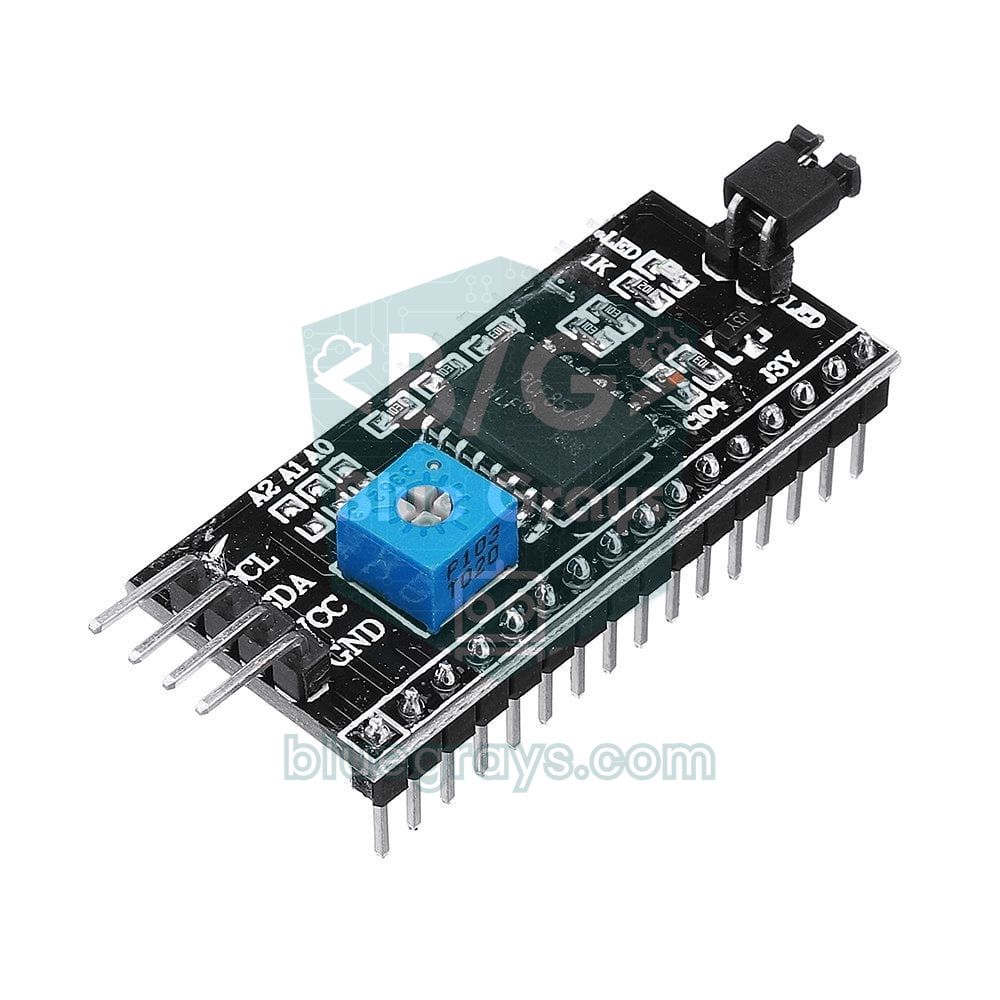
Thanks to the PCF8574 chip on its back, the I2C module carries all of the LCD's signals over two wires (SDA and SCL); the contrast potentiometer and backlight transistor are on the board too. As your project grows, that convenience matters: an Uno only has 20 digital and analog pins, and a parallel LCD uses six of them on its own. On the other hand, the parallel connection is faster, has no I2C address conflicts and needs no extra module. The table below sums up which is better when; for the I2C module setup, see the I2C LCD display article.
| Feature | Parallel (4-bit) | With I2C module |
|---|---|---|
| Arduino pins used | 6 | 2 (A4, A5) |
| Number of wires | 12 (including power and potentiometer) | 4 |
| Full screen refresh | Under 2 ms | About 20–30 ms at 100 kHz |
| Contrast adjustment | External potentiometer | Trimmer on the module |
| Switching the backlight off in software | Needs an extra transistor | lcd.noBacklight() |
| Library | LiquidCrystal (ships with the IDE) | LiquidCrystal I2C (installed separately) |
| Typical trouble | Wire clutter, loose connections | Address (0x27 / 0x3F) and pull-up issues |
Project ideas with a 16x2 LCD
- Digital thermometer: Show temperature and humidity from an NTC or a DHT11 in large text, writing the degree sign with lcd.write(223).
- Code lock: Show the code typed on a keypad as asterisks and trigger a relay if it's correct.
- Distance display: Show the distance measured by an HC-SR04 in centimetres and as a bar graph at the same time.
- Stopwatch and countdown: Start, stop and reset with two buttons, showing the time as minutes:seconds:hundredths.
- Mini game: Draw a runner and obstacles with custom characters and make it jump with a button.
- Menu system: Build a menu you scroll through and change settings in with a rotary encoder, and save the choices to EEPROM.
Wiring a 16x2 LCD without an I2C module may look like a mess of wires at first, but once you learn how the display takes commands you can use any character LCD, the 20x4 and even different microcontrollers with the same logic. In the BlueGrays app, the "Printing a Message on a 16x2 LCD", "Bouncing Text on an LCD" and "Measuring Distance with an LCD" projects walk you through this connection step by step with a wiring diagram and ready-made code.
Frequently asked questions
Why does my 16x2 LCD show black boxes?
If the boxes appear only on the top line, power and contrast are fine but the Arduino failed to initialise the display; check the RS, E and D4–D7 wires and the pin order in the LiquidCrystal constructor. If faint boxes appear on both lines, the contrast is too high and turning the potentiometer is enough.
Why is my LCD backlight on but no text shows?
The most common reason is contrast set too low: when V0 sits close to 5 V, the characters are invisible. Check that the potentiometer wiper is connected to V0 and turn it slowly. If the contrast is right and boxes show on the top line, the problem is in the data wires or the code.
Can a 16x2 LCD be used without a potentiometer?
Yes. A fixed 1–2.2 kΩ resistor between V0 and GND gives good contrast on most 5 V modules. The most reliable way is to find the value once with a potentiometer and then replace it with a fixed resistor. You can also connect V0 to a PWM pin through an RC filter and set the contrast in software.
Where does the LCD's RW pin connect?
If you'll only write to the display, connect RW (pin 5) to GND; this keeps the LCD permanently in write mode, which is how the LiquidCrystal library works. If RW is left floating, the display can randomly switch to read mode and drive the data lines, and nothing may appear. RW tied to GND also protects the pins of 3.3 V boards.
What's the difference between LiquidCrystal and LiquidCrystal_I2C?
LiquidCrystal drives the LCD directly from Arduino pins and ships with the Arduino IDE; it's used for the parallel connection. LiquidCrystal_I2C sends the same commands through a PCF8574 I2C module and must be installed separately. Most commands (print, setCursor, createChar) are the same in both; the I2C version adds lcd.init() for start-up and backlight() for the backlight.
Will my 16x2 LCD code work on a 20x4 LCD?
Yes, because the wiring and commands are the same; you only need to change lcd.begin(16, 2) to lcd.begin(20, 4). On a 20x4 display the rows follow the order 1, 3, 2, 4 in memory, so moving to each row with setCursor(0, row) is the cleanest approach. The backlight draws a little more current.
Projects to build after reading this
See all projects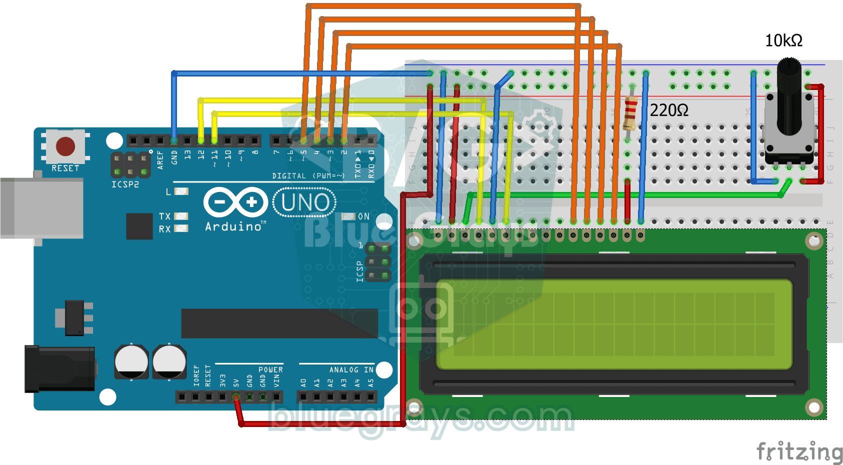
Print Message on 2x16 LCD Screen
Your first step to writing text on a screen. The two-line LCD screen first shows a waiting message, then writes a greeting on the top line and types a word letter by letter on the bottom line like a…
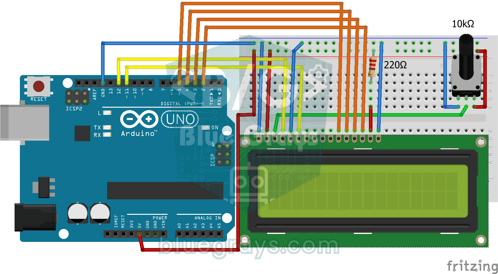
Bouncing Text Animation on LCD
On the top line of the LCD screen, the word BLUEGRAYS slides from one edge to the other and bounces back like a ball off a wall, over and over without end.
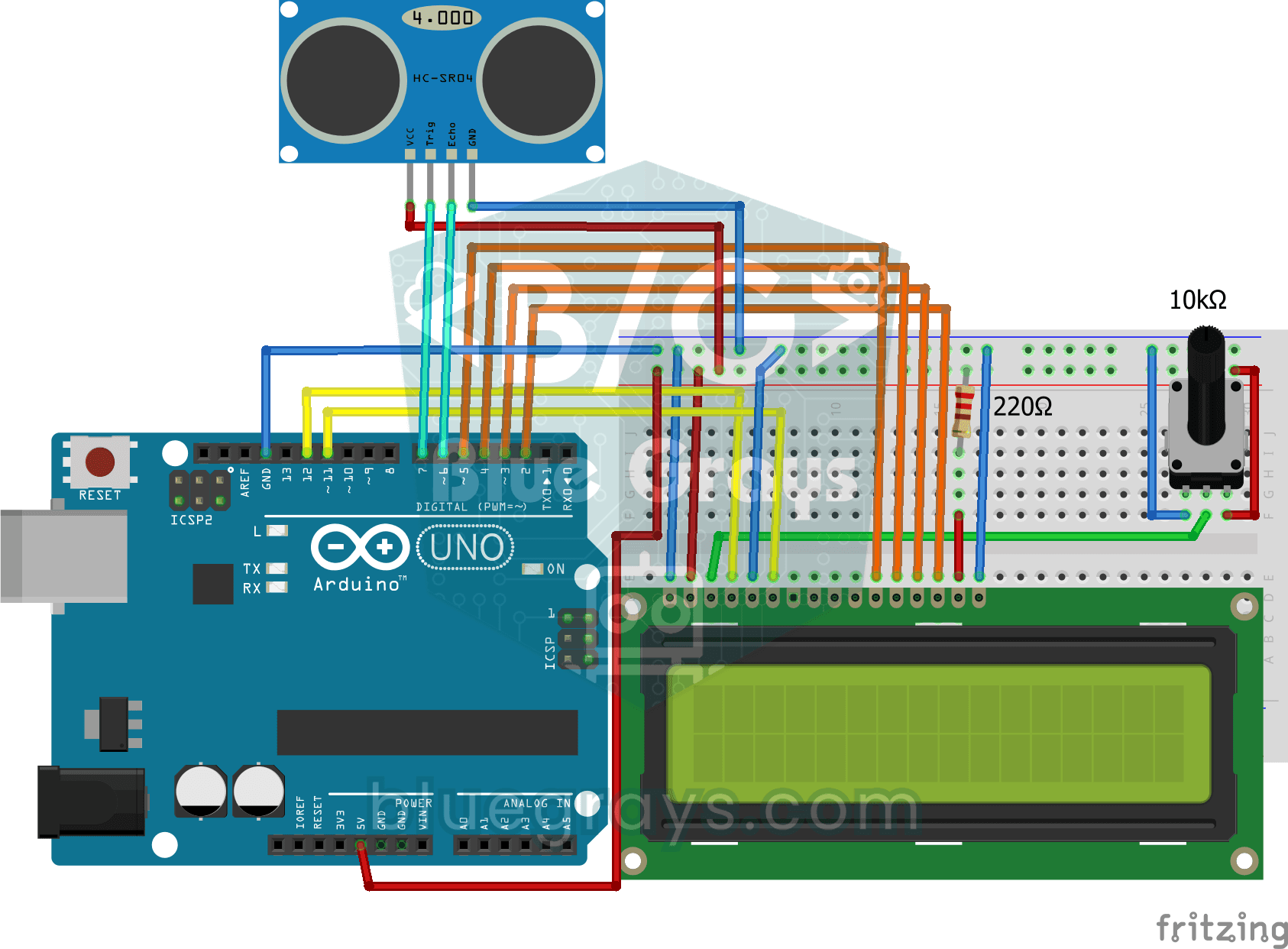
Measuring Distance Using LCD Display
A tool that measures distance without a ruler: move your hand back and forth in front of the sensor and watch the number change.
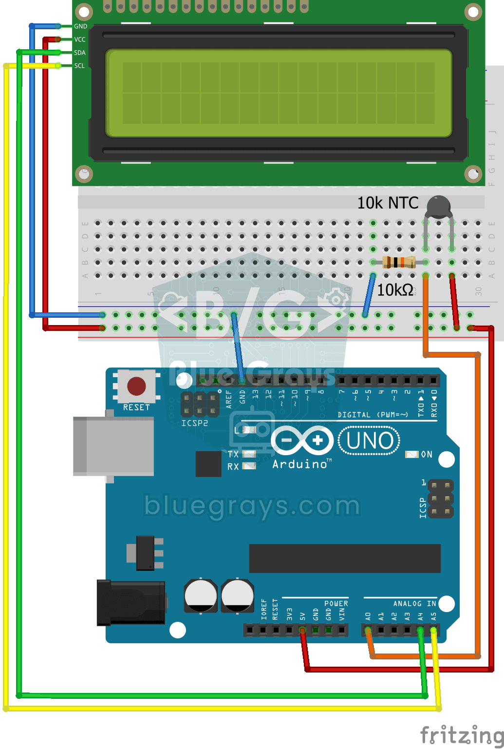
Temperature Measurement with NTC and 2x16 Lcd Display
Measure the temperature around you with a sensor that looks like a tiny bead. This part, called an NTC, lets electricity through more easily as it warms up; the Arduino reads that change, turns it…
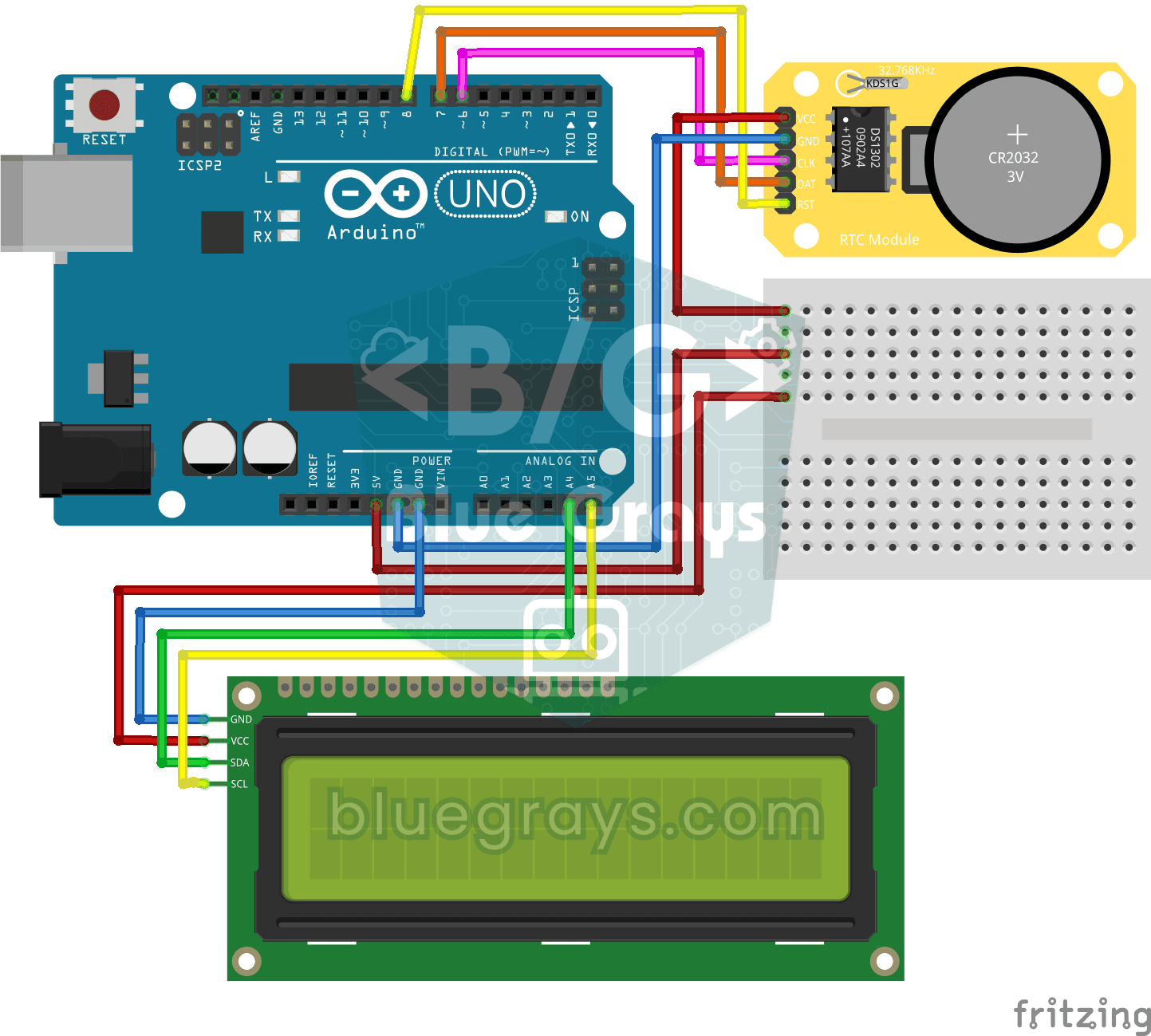
DS1302 RTC Clock with LCD Display
A little desk clock that keeps the time even when the power goes out. The DS1302 clock module keeps time thanks to its own tiny battery; every second the Arduino reads it and writes the time and date…
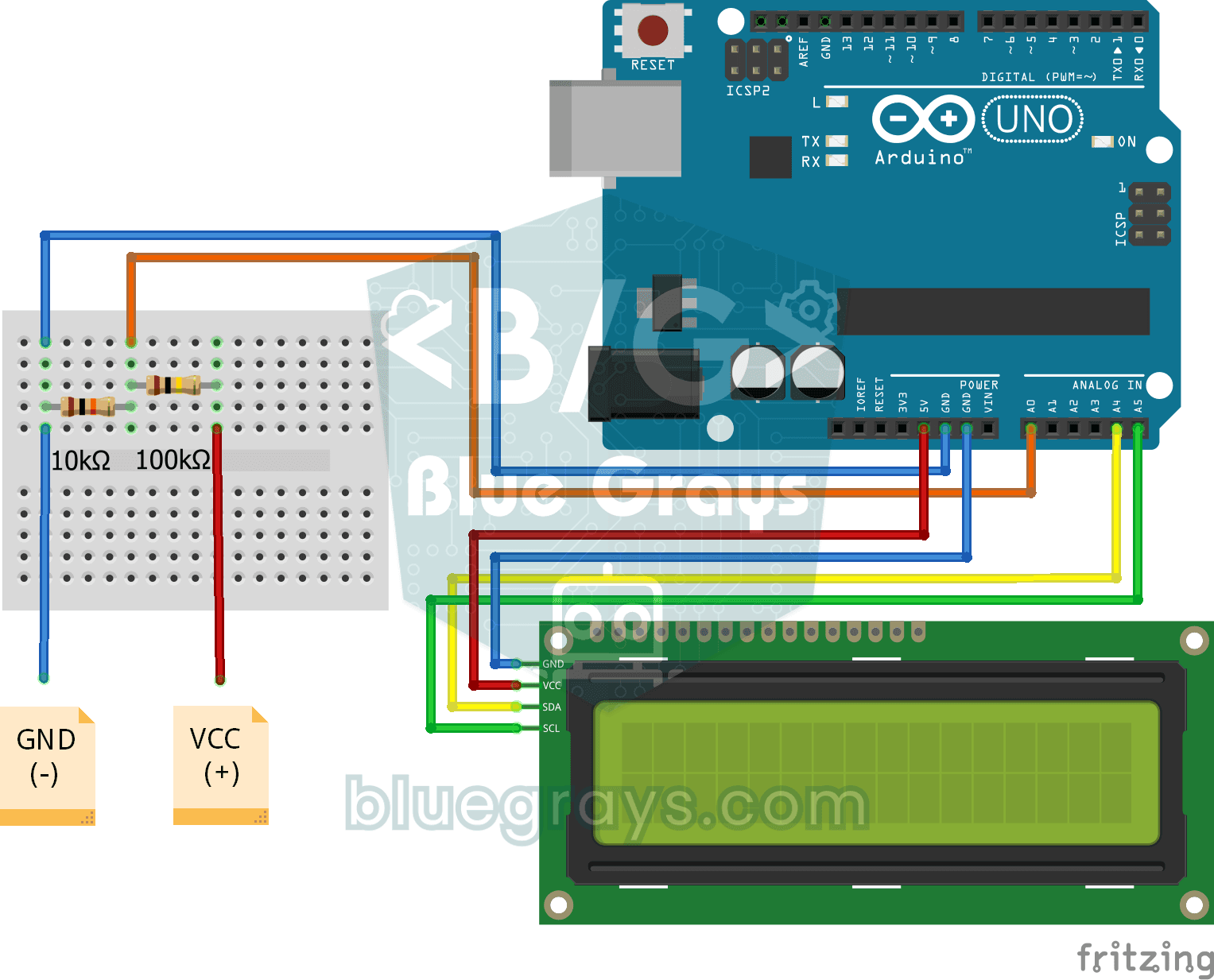
Digital Voltmeter with LCD Display
Find out how much voltage a battery or power adapter gives with a meter you built yourself.
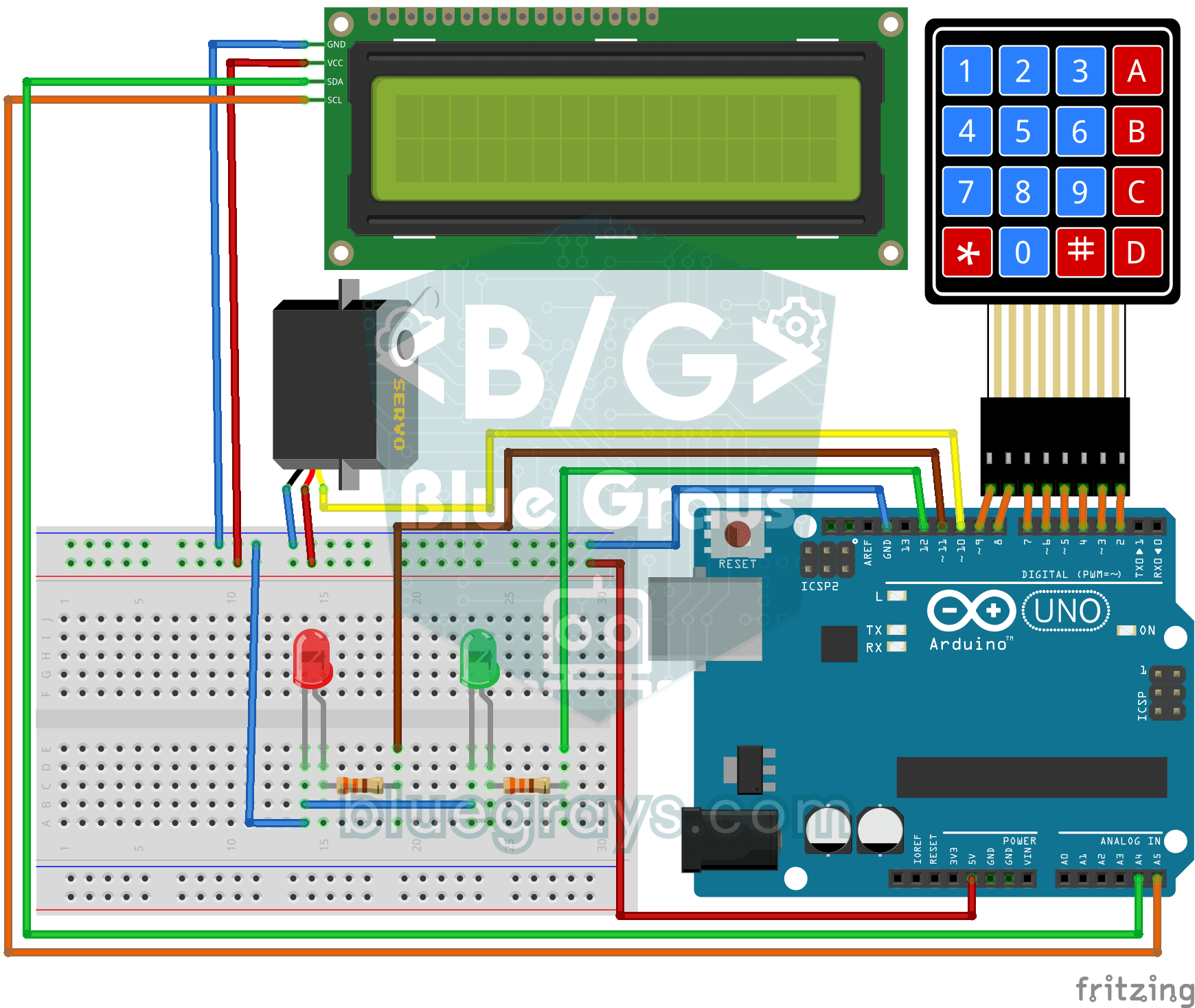
Password Lock with 4x4 Keypad and LCD
A small electronic door lock that keeps out anyone who doesn't know the code. You press the hash key and type the code on the keypad; if it is right, the screen says access granted, the green LED…

Arduino LCD Runner Game
Side scrolling endless runner game running on 16x2 character LCD screen. Hero runs automatically, player jumps over obstacles by pressing the button. Random obstacles appear on the top and bottom row. Passive buzzer plays opening melody, jumping sound, 50 point celebration sound and end of game melody. "BlueGrays - Arduino Projects" splash screen is shown on startup. The score is updated instantly in the upper right corner of the screen.