
NTC Thermistor Arduino Guide: Wiring, Beta and Steinhart-Hart
How to use an NTC thermistor with Arduino: voltage divider wiring, Beta (B3950) and Steinhart-Hart formulas, calibration, LCD thermometer, ESP32 and Pico code.
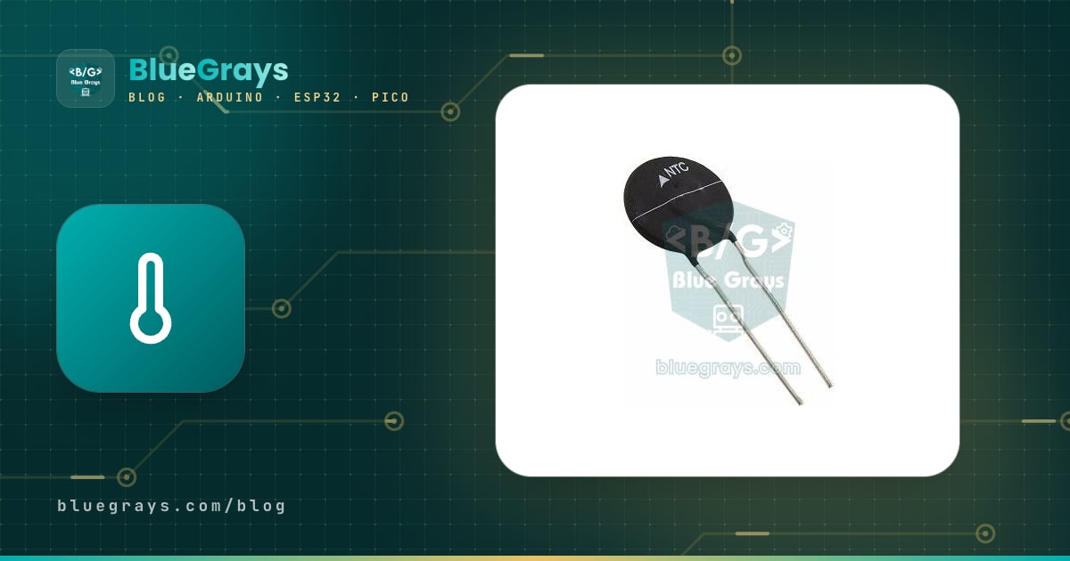
An NTC thermistor is a cheap, two-legged temperature sensor whose resistance drops as it gets warmer. To use an NTC thermistor with Arduino, you wire it with a fixed 10 kΩ resistor as a voltage divider, read the midpoint on an analog pin (A0), work out the thermistor's resistance from that reading and convert it to degrees Celsius with the Beta equation. No library is needed, one analog pin is enough, and when it's set up properly you get 0.1 °C resolution at room temperature. The bed and hotend of 3D printers, phone and laptop batteries, air conditioners, fridges and digital fever thermometers mostly measure temperature with NTC thermistors too.
In this article you'll learn, step by step, how a 10 kΩ NTC thermistor's resistance changes with temperature, how to wire the voltage divider and choose the fixed resistor, the Beta equation with B = 3950, the more accurate Steinhart-Hart equation and three-point calibration. Then you'll build a thermometer with an I2C LCD, repeat the measurement with the ADC of the ESP32 and Raspberry Pi Pico, and look at the difference between NTC and PTC, 3D printer and battery applications, and the most common mistakes.
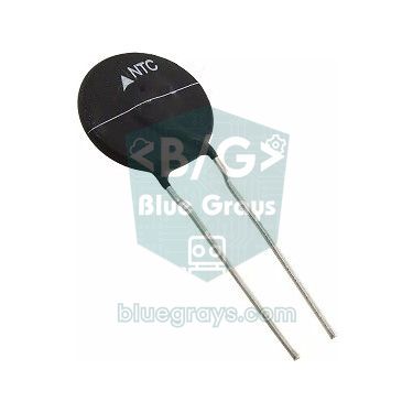
What is an NTC thermistor and how does it work?
The name thermistor combines "thermal" and "resistor": it's a resistor whose value changes noticeably with temperature. NTC stands for Negative Temperature Coefficient. It's made from a semiconducting ceramic produced by firing (sintering) metal oxides such as manganese, nickel and cobalt at high temperature. As the material warms up, more charge carriers take part in conduction, so the resistance falls. The change is large: an NTC with B = 3950 loses about 4.4% of its resistance per degree around 25 °C. For comparison, an ordinary metal film resistor changes by only 50–100 ppm per degree, i.e. 0.005–0.01%. This high sensitivity makes the NTC a cheap but very responsive sensor; the price you pay is that the relationship isn't linear.
| Property | Typical 10 kΩ NTC (B3950) |
|---|---|
| Nominal resistance (R25) | 10 kΩ at 25 °C; tolerance usually ±1%, ±3% or ±5% |
| B value | B25/50 = 3950 K (±1%); 3435 K and 3380 K models are also common |
| Sensitivity | About −4.4%/°C at 25 °C, about −2.8%/°C at 100 °C |
| Operating range | Epoxy bead about −40 … +125 °C; glass-encapsulated types up to 250–300 °C |
| Self-heating (dissipation constant) | Typically 1.5–2 mW/°C in still air |
| Thermal time constant | About 10–20 s for an epoxy bead in still air |
| Polarity | None; the legs can be swapped |
| Package types | Epoxy bead, glass (DO-35), stainless steel waterproof probe, SMD (0402, 0603), disc |
Resistance vs temperature: why isn't it linear?
An NTC's resistance changes exponentially with temperature: it falls very quickly in the cold and more slowly when hot. The table below shows the resistance of a 10 kΩ, B = 3950 NTC calculated with the Beta equation, plus the voltage and analogRead value you'll see on the Arduino Uno's A0 pin when this NTC sits in the upper leg of a 10 kΩ voltage divider powered from 5 V (the wiring in the next section). The last column shows how many degrees one ADC step represents, i.e. the measurement's resolution. Real manufacturers' tables can differ from these values by a few percent, especially at the ends of the range.
| Temperature | NTC resistance | A0 voltage (5 V) | analogRead | One step ≈ |
|---|---|---|---|---|
| −20 °C | 105.4 kΩ | 0.433 V | 89 | 0.20 °C |
| 0 °C | 33.6 kΩ | 1.146 V | 235 | 0.10 °C |
| 10 °C | 20.2 kΩ | 1.657 V | 339 | 0.09 °C |
| 20 °C | 12.5 kΩ | 2.219 V | 454 | 0.09 °C |
| 25 °C | 10.0 kΩ | 2.500 V | 512 | 0.09 °C |
| 30 °C | 8.04 kΩ | 2.772 V | 567 | 0.09 °C |
| 40 °C | 5.30 kΩ | 3.268 V | 669 | 0.11 °C |
| 50 °C | 3.59 kΩ | 3.680 V | 753 | 0.13 °C |
| 60 °C | 2.49 kΩ | 4.004 V | 819 | 0.17 °C |
| 80 °C | 1.27 kΩ | 4.436 V | 908 | 0.31 °C |
| 100 °C | 698 Ω | 4.674 V | 956 | 0.57 °C |
| 125 °C | 359 Ω | 4.827 V | 988 | 1.17 °C |
Two important conclusions follow from the table. First, the voltage divider is most sensitive when the NTC's resistance equals the fixed resistor, which in this example is around 25 °C: there, A0 changes by about 55 mV per degree and even the 10-bit Uno measures in 0.09 °C steps. That's five times better than the LM35, which gives only 0.49 °C resolution with the 5 V reference. Second, the resolution gets worse the further you move from that point; one step becomes 0.57 °C at 100 °C and 1.2 °C at 125 °C. So choose the fixed resistor close to the NTC's resistance at the temperature you'll measure most. To get the widest A0 swing over a given range, the fixed resistor should be the geometric mean of the NTC resistances at the two ends of the range: for 0–100 °C that's √(33.6 kΩ × 0.70 kΩ) ≈ 4.8 kΩ, so a standard 4.7 kΩ; for 60–100 °C about 1.3 kΩ, so 1.2 kΩ or 1.5 kΩ.
NTC thermistor wiring: voltage divider (Uno, ESP32, Pico)
Arduino's analog inputs measure voltage, not resistance. That's why you put the NTC in series with a fixed resistor to form a voltage divider: the voltage at the point where the two resistors meet changes with the NTC's resistance, and therefore with temperature. It's exactly the circuit you use with an LDR; the only difference is that the resistor reacts to temperature instead of light. In the code in this article the NTC sits in the upper leg (connected to the supply) and the 10 kΩ resistor in the lower leg (connected to GND), so the reading rises as it gets warmer, which feels intuitive. You can calculate the output voltage for different resistor values in the Voltage divider tool and check the fixed resistor's colour code with the Resistor colour code tool.
| Connection | Arduino Uno | ESP32 | Raspberry Pi Pico |
|---|---|---|---|
| NTC leg 1 | 5V | 3V3 | 3V3(OUT), pin 36 |
| NTC leg 2 + one end of the 10 kΩ resistor | A0 | GPIO 34 (ADC1) | GP26 / ADC0, pin 31 |
| Other end of the 10 kΩ resistor | GND | GND | AGND, pin 33 |
| 100 nF capacitor (optional) | Between A0 and GND | Between GPIO 34 and GND | Between GP26 and AGND |
| Wiring | A0 voltage | NTC resistance (10-bit) | analogRead when warmer |
|---|---|---|---|
| NTC on top: 5V – NTC – A0 – 10 kΩ – GND | Vcc × Rs / (Rs + Rntc) | Rntc = Rs × (1023 − adc) / adc | Rises |
| NTC on bottom: 5V – 10 kΩ – A0 – NTC – GND | Vcc × Rntc / (Rs + Rntc) | Rntc = Rs × adc / (1023 − adc) | Falls |
This circuit has a nice property: it makes a ratiometric measurement. By default the Uno's ADC uses the 5 V supply as its reference, and the divider is powered from the same 5 V. Even if USB delivers 4.8 V instead of 5.0 V, the divider output and the ADC reference drop by the same proportion and the analogRead value doesn't change. So you don't need to know the supply voltage for an NTC reading, and you don't have to fight with the reference voltage as you do with the LM35. For the same reason, don't use analogReference(INTERNAL) in an NTC circuit: with a 1.1 V reference the ratio breaks and the calculation goes wrong. What really decides the accuracy is the value of the fixed resistor; a 5% resistor alone can cause about 1 °C of error. So use a 1% metal film resistor, or measure your resistor's real value with a multimeter and put it in the code.
Calculating temperature with the Beta equation (B = 3950)
Manufacturers describe an NTC with two numbers: its resistance at 25 °C (R0 = 10 kΩ) and its B value (Beta). With these two numbers the Beta equation gives the temperature for any resistance: 1/T = 1/T0 + (1/B) × ln(R/R0). Here T and T0 are in kelvin (T0 = 25 + 273.15 = 298.15 K) and ln is the natural logarithm; subtract 273.15 to convert the result to Celsius. Example: if the NTC measures 5300 Ω, ln(5300/10000) = −0.635; 1/T = 0.003354 − 0.000161 = 0.003193 and T = 313.2 K, which is about 40 °C. The small numbers next to the B value tell you between which two temperatures it was measured: B25/50 = 3950 means B was calculated from the resistances at 25 °C and 50 °C. If you don't have a datasheet, you can find B yourself: measure the resistance at two temperatures and use B = ln(R1/R2) / (1/T1 − 1/T2). For example, if you measure 10,000 Ω at 25 °C and 3588 Ω at 50 °C, you get B ≈ 3950.
First measurement with Arduino, step by step
- Plug the NTC and the 10 kΩ resistor into the breadboard; connect one leg of the NTC to 5V and the other leg to one end of the resistor.
- Connect the other end of the resistor to GND, and run a jumper wire from the point where the NTC and the resistor meet to A0.
- Upload the code below and open the Serial Monitor at 9600 baud.
- At room temperature you should see a value around 20–25 °C. Hold the NTC between two fingers; within a few seconds the value should climb towards 30 °C.
- If the value falls as it warms up, the NTC and the resistor are swapped: either fix the wiring or replace the formula in the code with the "NTC on bottom" formula.
1const int NTC_PIN = A0;            // NTC ile 10k direncin birleştiği nokta / junction of the NTC and the 10k resistor
2const float SERIES_R = 10000.0;    // sabit direnç, ölçtüğün değeri yaz / fixed resistor, write your measured value
3const float R_NOMINAL = 10000.0;   // NTC'nin 25 °C'deki direnci / NTC resistance at 25 °C
4const float T_NOMINAL_K = 298.15;  // 25 °C kelvin cinsinden / 25 °C in kelvin
5const float BETA_K = 3950.0;       // B25/50 değeri (veri sayfası) / B25/50 value (datasheet)
6const int SAMPLES = 16;            // ortalama için ölçüm sayısı / number of samples to average
7
8void setup() {
9  Serial.begin(9600);
10}
11
12void loop() {
13  long sum = 0;
14  for (int i = 0; i < SAMPLES; i++) {
15    sum += analogRead(NTC_PIN);
16    delay(2);
17  }
18  float adc = sum / (float)SAMPLES;                      // ortalama ham değer / average raw value
19
20  if (adc < 1.0 || adc > 1022.0) {                       // kablo kopuk ya da kısa devre / open or shorted wire
21    Serial.println(F("Sensor hatasi / Sensor error"));
22    delay(1000);
23    return;
24  }
25
26  float rNtc = SERIES_R * (1023.0 - adc) / adc;          // NTC üstte bağlantı / NTC on the high side
27  float tempK = 1.0 / (1.0 / T_NOMINAL_K + log(rNtc / R_NOMINAL) / BETA_K);   // Beta denklemi / Beta equation
28  float tempC = tempK - 273.15;                          // kelvin -> santigrat / kelvin -> Celsius
29
30  Serial.print(F("ADC: "));
31  Serial.print(adc, 1);
32  Serial.print(F("  R: "));
33  Serial.print(rNtc, 0);
34  Serial.print(F(" ohm  Sicaklik / Temp: "));
35  Serial.print(tempC, 2);
36  Serial.println(F(" C"));
37  delay(1000);
38}
On every measurement the code reads A0 sixteen times and averages the result; this smooths out the ADC's one- or two-step jitter. If the average is below 1 or above 1022, the NTC's wire is broken or shorted, and the code prints an error message instead of a meaningless temperature. Then it calculates the NTC's resistance from the average and the temperature from that with the Beta equation. In Arduino the log() function returns the natural logarithm (ln); log10() is the base-10 logarithm, and mixing them up makes the result completely wrong as you move away from 25 °C. In the Serial Monitor you'll see lines like "ADC: 512.3 R: 9969 ohm Sicaklik / Temp: 25.07 C".
The Steinhart-Hart equation: a more accurate result
The Beta equation is very good within the range where B was measured (usually 25–50 °C), but it drifts as you move away from it, because a real NTC's B value changes slightly with temperature. Over a wide range such as 0–100 °C the error can exceed 1 °C. For a more accurate result, the three-coefficient Steinhart-Hart equation is used: 1/T = A + B × ln(R) + C × (ln R)³. The Beta equation is actually the special case of this equation with C = 0. The coefficients are calculated from three resistance values measured at three different temperatures; with three well-chosen points the equation is typically better than 0.1 °C within the calibrated range. Instead of solving for A, B and C by hand, the code below calculates the coefficients from your three measured points itself, inside setup().
1const int NTC_PIN = A0;
2const float SERIES_R = 10000.0;    // ölçtüğün sabit direnç / your measured fixed resistor
3
4// Kalibrasyon noktaları: örnek değerler, kendi ölçümlerini yaz / calibration points: sample values, use your own
5const float CAL_T1 = 0.0,  CAL_R1 = 32900.0;   // buzlu su / ice water
6const float CAL_T2 = 25.0, CAL_R2 = 10000.0;   // oda, referans termometreyle / room, against a reference thermometer
7const float CAL_T3 = 98.5, CAL_R3 = 690.0;     // kaynayan su / boiling water
8
9float shA, shB, shC;               // Steinhart-Hart katsayıları / coefficients
10
11void computeCoefficients() {
12  float L1 = log(CAL_R1), L2 = log(CAL_R2), L3 = log(CAL_R3);
13  float Y1 = 1.0 / (CAL_T1 + 273.15);
14  float Y2 = 1.0 / (CAL_T2 + 273.15);
15  float Y3 = 1.0 / (CAL_T3 + 273.15);
16  float g2 = (Y2 - Y1) / (L2 - L1);
17  float g3 = (Y3 - Y1) / (L3 - L1);
18  shC = ((g3 - g2) / (L3 - L2)) / (L1 + L2 + L3);
19  shB = g2 - shC * (L1 * L1 + L1 * L2 + L2 * L2);
20  shA = Y1 - (shB + shC * L1 * L1) * L1;
21}
22
23float readResistance() {
24  long sum = 0;
25  for (int i = 0; i < 16; i++) {
26    sum += analogRead(NTC_PIN);
27    delay(2);
28  }
29  float adc = sum / 16.0;
30  if (adc < 1.0 || adc > 1022.0) return -1.0;            // sensör hatası / sensor error
31  return SERIES_R * (1023.0 - adc) / adc;                // NTC üstte / NTC on the high side
32}
33
34void setup() {
35  Serial.begin(9600);
36  computeCoefficients();           // katsayıları bir kez hesapla / compute the coefficients once
37}
38
39void loop() {
40  float r = readResistance();
41  if (r < 0) {
42    Serial.println(F("Sensor hatasi / Sensor error"));
43  } else {
44    float lnR = log(r);
45    float tempK = 1.0 / (shA + shB * lnR + shC * lnR * lnR * lnR);   // Steinhart-Hart
46    Serial.print(F("R: "));
47    Serial.print(r, 0);
48    Serial.print(F(" ohm  Sicaklik / Temp: "));
49    Serial.print(tempK - 273.15, 2);
50    Serial.println(F(" C"));
51  }
52  delay(1000);
53}
The three points in the code are examples; measure your own NTC and replace them. With these sample values Steinhart-Hart gives exactly the right result at 0 °C, 25 °C and 98.5 °C. Feed the same resistances to the Beta equation (B = 3950), however, and the 0 °C point comes out as 0.4 °C and the 98.5 °C point as 100.4 °C, an error of about 2 °C at high temperature. Pick points at both ends and in the middle of the range you'll measure; outside the calibrated range (for example at −20 °C with these coefficients) the error grows again. On the Uno a float is only 32 bits, but that's enough for this calculation: the results match a double-precision calculation to within 0.01 °C.
Calibration: turn your NTC into a reliable thermometer
- Measure the fixed resistor: measure the real value of the 10 kΩ resistor with a multimeter and enter it as SERIES_R in the code; a 1% deviation on its own means about 0.2 °C of error.
- Make the NTC waterproof: don't dip a bare epoxy NTC in water; insulate its legs with heat-shrink tubing and silicone, or use a ready-made NTC in a stainless steel probe.
- 0 °C point: fill a glass to the brim with crushed ice, add a little cold water and stir. Keep the NTC in the middle of the glass for 2–3 minutes and, once the value settles, note the R value from the Serial Monitor.
- Room temperature point: leave the NTC next to a reliable digital thermometer for 10 minutes somewhere without draughts; note the thermometer's reading and the NTC's resistance.
- High temperature point: at sea level water boils at 100 °C, but the boiling point drops by about 1 °C for every 300 m of altitude (about 96.7 °C at 1000 m). Dip the NTC into boiling water without touching the bottom of the pot and note the resistance.
- Put the values in the code: enter the three points into the Steinhart-Hart code. If you'll only measure around room temperature, a single-point offset correction (subtracting the constant difference) is often enough.
NTC thermometer on an LCD
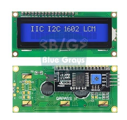
To show the reading without a computer, let's add a 16x2 I2C LCD. Connect the display's SDA pin to A4, SCL to A5, VCC to 5V and GND to GND; the NTC circuit stays the same. The code uses the LiquidCrystal I2C library, which you can install from the Library Manager. The display's address is usually 0x27, on some modules 0x3F. For the degree sign we print character 223 from the LCD's character table. The display also shows the lowest and highest temperature measured since the Arduino was switched on in the bottom row.
1#include <Wire.h>
2#include <LiquidCrystal_I2C.h>
3
4LiquidCrystal_I2C lcd(0x27, 16, 2);   // adres 0x27 ya da 0x3F / address 0x27 or 0x3F
5
6const int NTC_PIN = A0;
7const float SERIES_R = 10000.0;
8const float R_NOMINAL = 10000.0;
9const float T_NOMINAL_K = 298.15;
10const float BETA_K = 3950.0;
11
12float minC = 999.0;                   // en düşük değer / lowest value
13float maxC = -999.0;                  // en yüksek değer / highest value
14
15float readTempC() {
16  long sum = 0;
17  for (int i = 0; i < 16; i++) {
18    sum += analogRead(NTC_PIN);
19  }
20  float adc = sum / 16.0;
21  if (adc < 1.0 || adc > 1022.0) return NAN;             // sensör hatası / sensor error
22  float r = SERIES_R * (1023.0 - adc) / adc;
23  return 1.0 / (1.0 / T_NOMINAL_K + log(r / R_NOMINAL) / BETA_K) - 273.15;
24}
25
26void setup() {
27  lcd.init();
28  lcd.backlight();
29}
30
31void loop() {
32  float t = readTempC();
33  lcd.clear();
34  if (isnan(t)) {
35    lcd.print(F("Sensor hatasi"));
36  } else {
37    if (t < minC) minC = t;
38    if (t > maxC) maxC = t;
39    lcd.print(F("Sicaklik "));
40    lcd.print(t, 1);
41    lcd.print((char)223);             // derece işareti / degree symbol
42    lcd.print('C');
43    lcd.setCursor(0, 1);              // ikinci satır / second row
44    lcd.print(F("Min"));
45    lcd.print(minC, 1);
46    lcd.print(F(" Max"));
47    lcd.print(maxC, 1);
48  }
49  delay(1000);
50}
NTC thermistor with the ESP32
The ESP32's ADC is 12-bit (0–4095) and the chip runs on 3.3 V, so power the divider from the 3V3 pin. Always connect the NTC to an ADC1 pin (GPIO 32–39); ADC2 pins can't be read while Wi-Fi is on. You can see your board's pin map in the Pinout tool. There's an important difference here: the ESP32's ADC doesn't use the supply voltage as its reference, but an internal reference of about 1.1 V plus the selected attenuation. So the ratiometric measurement you get on the Uno doesn't happen automatically, and you need to know the real value of the 3V3 rail. That's why the code reads millivolts with analogReadMilliVolts(), which uses the calibration data written into the chip at the factory, and calculates the resistance from the 3V3 value you measured with a multimeter. According to Espressif's documentation, the classic ESP32 can measure 150–3100 mV at the default 11 dB attenuation, but the recommended and most linear region is 150–2450 mV. These limits set the temperature range you can measure, depending on the wiring:
| Wiring (3.3 V, 10 kΩ) | 150–2450 mV (most accurate) | 150–3100 mV (full range) |
|---|---|---|
| NTC on top: 3V3 – NTC – GPIO 34 – 10 kΩ – GND | About −30 … +50 °C | About −30 … +100 °C |
| NTC on bottom: 3V3 – 10 kΩ – GPIO 34 – NTC – GND | About +3 … +114 °C | About −26 … +114 °C |
1const int NTC_PIN = 34;            // ADC1_CH6, Wi-Fi açıkken de çalışır / works while Wi-Fi is on
2const float VCC_MV = 3300.0;       // 3V3 pinini multimetreyle ölçüp yaz / measure the 3V3 pin and write it here
3const float SERIES_R = 10000.0;
4const float R_NOMINAL = 10000.0;
5const float T_NOMINAL_K = 298.15;
6const float BETA_K = 3950.0;
7const int SAMPLES = 64;            // ortalama için ölçüm sayısı / number of samples to average
8
9void setup() {
10  Serial.begin(115200);
11  analogReadResolution(12);                     // 0–4095
12  analogSetPinAttenuation(NTC_PIN, ADC_11db);   // varsayılan zayıflatma / default attenuation
13}
14
15void loop() {
16  uint32_t sum = 0;
17  for (int i = 0; i < SAMPLES; i++) {
18    sum += analogReadMilliVolts(NTC_PIN);       // kalibre edilmiş mV / calibrated millivolts
19    delay(1);
20  }
21  float mv = sum / (float)SAMPLES;
22
23  if (mv < 150.0 || mv > 3100.0) {              // ADC aralığı dışında / outside the ADC range
24    Serial.println("Aralik disi / Out of range");
25    delay(1000);
26    return;
27  }
28
29  float rNtc = SERIES_R * (VCC_MV - mv) / mv;   // NTC üstte / NTC on the high side
30  float tempC = 1.0 / (1.0 / T_NOMINAL_K + log(rNtc / R_NOMINAL) / BETA_K) - 273.15;
31  Serial.printf("Gerilim / Voltage: %.0f mV  R: %.0f ohm  Sicaklik / Temp: %.2f C\n", mv, rNtc, tempC);
32  delay(1000);
33}
For an indoor or outdoor thermometer, the NTC-on-top wiring is ideal. If you'll measure above 50 °C, for example a kettle, a coffee machine or a 3D printer bed, move the NTC to the lower leg and change the formula to Rntc = Rs × mV / (Vcc − mV). With Wi-Fi on, the ESP32's current spikes cause small ripples on the 3V3 rail; averaging 64 readings and adding a 100 nF capacitor between GPIO 34 and GND improves the result noticeably. If you're new to the ESP32, read the What is the ESP32 article for the setup.
NTC with the Raspberry Pi Pico and MicroPython
The Pico's 12-bit ADC is on pins GP26, GP27 and GP28; in MicroPython read_u16() returns the result scaled to 0–65535. The Pico's ADC reference (ADC_VREF) is derived on the board from the 3.3 V rail through a small RC filter. If you also power the divider from the 3V3(OUT) pin, the measurement is roughly ratiometric just as on the Uno and the formula stays the same; you simply use 65535 instead of 1023. The Pico's ADC is a little noisy and jumps slightly at certain codes, so averaging is essential here too. Using AGND (pin 33) as the analog ground reduces the noise a bit. If you're using the Pico for the first time, you'll find the MicroPython setup in the What is the Raspberry Pi Pico article.
1from machine import ADC
2import math
3import time
4
5ntc = ADC(26)                # GP26 = ADC0, fiziksel pin 31 / physical pin 31
6SERIES_R = 10000             # sabit direnç / fixed resistor
7R_NOMINAL = 10000            # NTC'nin 25 °C'deki direnci / NTC resistance at 25 °C
8T_NOMINAL_K = 298.15         # 25 °C kelvin cinsinden / 25 °C in kelvin
9BETA_K = 3950                # B25/50 değeri / B25/50 value
10SAMPLES = 64                 # ortalama için ölçüm sayısı / number of samples to average
11
12
13def read_temp_c():
14    total = 0
15    for _ in range(SAMPLES):
16        total += ntc.read_u16()          # 0–65535
17    raw = total / SAMPLES
18    if raw < 100 or raw > 65435:
19        return None                      # kopuk ya da kısa devre / open or shorted
20    r_ntc = SERIES_R * (65535 - raw) / raw          # NTC üstte / NTC on the high side
21    temp_k = 1 / (1 / T_NOMINAL_K + math.log(r_ntc / R_NOMINAL) / BETA_K)
22    return temp_k - 273.15
23
24
25while True:
26    t = read_temp_c()
27    if t is None:
28        print("Sensor hatasi / Sensor error")
29    else:
30        print("Sicaklik / Temp: {:.2f} C".format(t))
31    time.sleep(1)
In MicroPython math.log() is also the natural logarithm, so you use the same formula as in the Arduino code. The Pico also has a built-in temperature sensor (ADC(4)), but it measures the chip's own temperature rather than the surroundings and usually reads a few degrees high while running. For ambient temperature an external NTC is far more accurate. If you want to use Steinhart-Hart coefficients, you can translate the computeCoefficients() function from the Arduino code to Python in a few lines.
NTC vs PTC: what's the difference?
In PTC (Positive Temperature Coefficient) thermistors the resistance rises with temperature. The most common type of PTC is used for protection rather than measurement: switching PTCs made of barium titanate ceramic stay at low resistance up to a certain temperature (the Curie point), and above it their resistance suddenly jumps by hundreds or thousands of times. Overheating protection in motor windings and self-limiting PTC heaters work on this principle. Polymer resettable fuses (polyfuses) behave in a similar way; the 500 mA fuse on the Arduino Uno's USB line is one of them. Silicon PTC sensors such as the KTY81, on the other hand, change almost linearly at about 0.7–0.8%/°C. Platinum RTDs like the PT100 and PT1000 also have a positive coefficient, but they're metal sensors, not thermistors; they measure 100 Ω or 1000 Ω at 0 °C, can go above 500 °C and need an amplifier such as the MAX31865 to be read.
| Property | NTC thermistor | Switching PTC | PT100 / PT1000 (RTD) |
|---|---|---|---|
| Resistance when warmer | Falls (about −4.4%/°C at 25 °C) | Changes little, then jumps at the switching temperature | Rises (about +0.385%/°C) |
| Curve | Exponential, not linear | Sudden jump (like a switch) | Almost linear |
| Typical range | −40 … +125 °C (250–300 °C in glass) | Switching temperature chosen per model (e.g. 80 °C, 120 °C) | −200 … +500 °C and above |
| Main use | Temperature measurement, inrush current limiting | Overheating and overcurrent protection | Precise industrial measurement |
| Reading with Arduino | Voltage divider + analog pin | Not usually used for measurement | With an amplifier module such as the MAX31865 |
| Price | Very cheap | Cheap | More expensive |
3D printer and battery applications
In 3D printers both the hotend and the bed temperature are mostly measured with NTC thermistors. Here 100 kΩ NTCs are used instead of 10 kΩ ones, because at 250 °C a 10 kΩ NTC drops to around 35 Ω and the measurement loses its resolution; the configuration file of the popular Marlin firmware even warns, for the generic 10 kΩ thermistor, "do not use for a hotend, it gives bad resolution at high temp". On 8-bit boards such as RAMPS the thermistor inputs are pulled up to 5 V with a 4.7 kΩ resistor, and Marlin converts the ADC value to temperature with ready-made tables; one of the types defined for 100 kΩ B3950 thermistors is number 11. If the thermistor wire breaks, the ADC reads its maximum, the firmware takes this as extreme cold and shows Err: MINTEMP; with a short circuit you get Err: MAXTEMP. If the thermistor slips out of its socket, the heater keeps heating but the measured value doesn't rise; Marlin catches this with its THERMAL RUNAWAY protection and switches the heaters off. Never disable this protection.
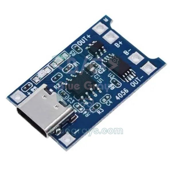
Lithium-ion cells shouldn't be charged below 0 °C or above about 45 °C; charging in the cold causes metallic lithium to build up inside the cell and does permanent damage. That's why most phone, laptop and e-bike batteries have an NTC glued to the cells, and the third terminal on the battery connector (marked T or NTC) usually goes to this thermistor. Pin 1 (TEMP) of the popular TP4056 charger chip is there for this job: according to its datasheet, if the voltage on this pin stays below 45% or above 80% of the input voltage for more than 0.15 seconds, charging is suspended. In your own battery project you can glue an NTC to the cell, read it with an Arduino and cut the charging circuit with a MOSFET when the temperature leaves the limits. In power supplies, large disc NTCs limit the inrush current that flows into the capacitors when the device is switched on; as they warm up, their resistance falls from a few ohms to below one ohm, so they cause very little loss in normal operation.
NTC thermistor project ideas
- Fan thermostat with hysteresis: switch a fan on with a relay module when the temperature passes 30 °C and off when it drops to 28 °C; the 2-degree gap stops the relay from clicking on and off constantly.
- Aquarium thermometer with a waterproof probe: measure the water temperature with a stainless steel NTC probe and sound a buzzer if the heater fails.
- Pocket thermometer with an OLED display: show the temperature and a graph of the last hour on an OLED display.
- 3D printer enclosure monitor: measure the temperature inside the closed enclosure and start an exhaust fan above 45 °C.
- Battery temperature guard: watch the cell temperature while charging, cut charging outside 0–45 °C and warn with an LED.
- Wi-Fi temperature logger: with an ESP32, write a reading to an SD card every minute or show it on a web page you open on your phone.
Common mistakes and how to fix them
| Symptom | Likely cause | Fix |
|---|---|---|
| Value is always 1023 or 0 | No fixed resistor, broken wire or shorted NTC | Check the divider; at 25 °C a multimeter should show about 2.5 V on A0 |
| Temperature drops when it warms up | NTC and fixed resistor are swapped | Fix the wiring or use the formula for the other wiring |
| Result is −273.15 °C, inf or nan | analogRead returns 0, causing a division by zero | Check the wire; don't remove the range check from the code |
| Correct around 25 °C, very wrong further away | log10() used instead of ln, or wrong B value (e.g. 3950 entered for a 3435 NTC) | Use log() and enter the B value from the NTC's datasheet |
| Value is always 1–2 °C too high | Self-heating, or the NTC is close to the regulator or the ESP32 module | Power the divider only while measuring, move the NTC away from the board on a cable |
| Readings jitter | Noise, long wires or poor breadboard contact | Average readings, add a 100 nF capacitor, twist the wires |
| Nonsense values on the ESP32 when cold or hot | The voltage is outside the ADC's linear 150–2450 mV region | Choose the wiring to suit your range (see the ESP32 table) |
| ESP32 reading fails when Wi-Fi starts | The NTC is on an ADC2 pin | Use one of the ADC1 pins, GPIO 32–39 |
| Very slow response | Thermal mass of a thick probe or housing | That's normal; for fast response choose a thin epoxy bead or an SMD NTC |
The NTC thermistor teaches you to turn a cheap part into an accurate thermometer with a single resistor and a few lines of maths: voltage divider, ADC, logarithms and calibration all in one. You'll use the same approach with other analog sensors later; to make your readings even smoother, take a look at sensor data filtering techniques. In the BlueGrays app you'll find temperature measurement with an NTC and a 2x16 LCD, temperature and humidity with the DHT11, an ESP32 temperature station with an LCD and a temperature logger, each with step-by-step circuit diagrams and ready-to-use code.
Frequently asked questions
What is an NTC thermistor used for?
An NTC thermistor is a semiconductor resistor whose resistance drops as its temperature rises. It's mostly used to measure temperature: 3D printers, air conditioners, fridges, battery packs and digital thermometers usually measure temperature with an NTC. Large disc types are used to limit inrush current in power supplies.
How do you test an NTC thermistor with a multimeter?
Set the multimeter to resistance and measure across the NTC's two legs; a 10 kΩ NTC should read about 10 kΩ at 25 °C and about 12.5 kΩ at 20 °C. Then hold the NTC between your fingers: the resistance should drop clearly within a few seconds. If the display shows OL (open circuit) or a value close to zero, the thermistor is faulty.
What is the difference between NTC and PTC?
An NTC's resistance falls as it warms up, while a PTC's rises. NTCs are mostly used to measure temperature and to limit inrush current. The most common PTCs are protection parts whose resistance jumps suddenly at a certain temperature; motor overheating protection and self-limiting heaters work this way.
What resistor should I use with a 10k NTC thermistor?
If you'll measure around room temperature, use a resistor equal to the NTC's value at 25 °C, i.e. 10 kΩ; the divider is most sensitive at that temperature. For a specific range, the best value is the geometric mean of the NTC resistances at the two ends of the range, for example about 4.7 kΩ for 0–100 °C. Choose a 1% metal film resistor for accuracy.
What does the B value (3950) of a thermistor mean?
The B value is a material constant that shows how quickly the NTC's resistance changes with temperature, and its unit is kelvin. B25/50 = 3950 means it was calculated from the resistances at 25 °C and 50 °C. If you don't use your NTC's real B value in the code, the error grows as you move away from 25 °C.
Which is better: NTC thermistor, DS18B20 or LM35?
For speed, low cost and small size, choose an NTC; for ±0.5 °C accuracy without calibration and long cables, the DS18B20 is better. The LM35 gives a linear analog output but needs at least 4 V, which makes it awkward with the 3.3 V ESP32 and Pico. Above 125 °C (for example a 3D printer hotend) you need a glass-encapsulated NTC, a PT100 or a thermocouple.
Projects to build after reading this
See all projects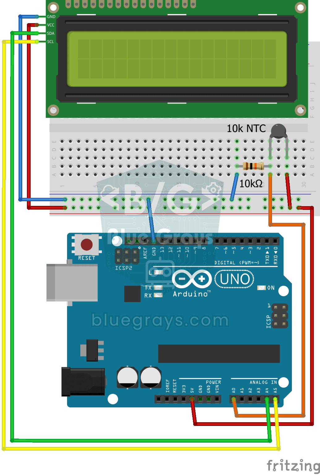
Temperature Measurement with NTC and 2x16 Lcd Display
Measure the temperature around you with a sensor that looks like a tiny bead. This part, called an NTC, lets electricity through more easily as it warms up; the Arduino reads that change, turns it int
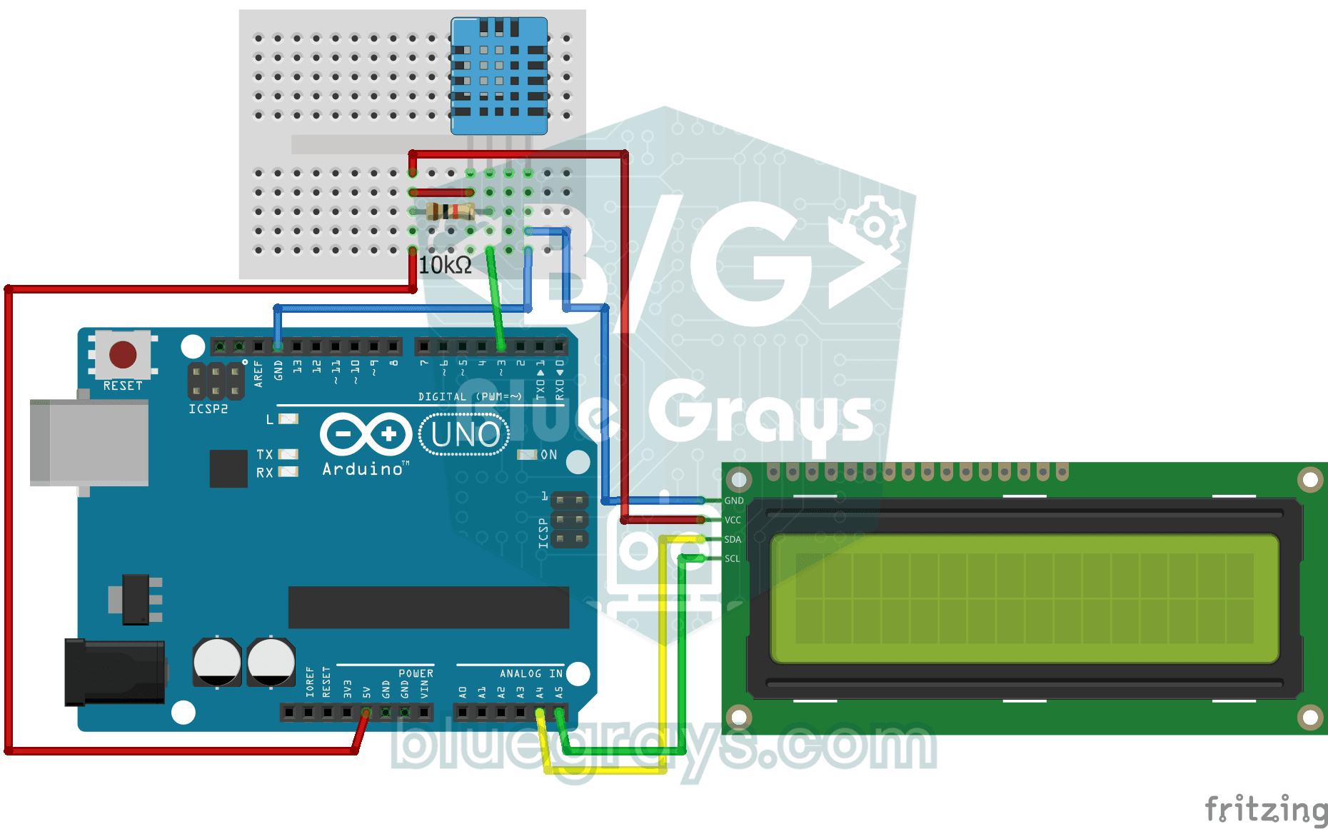
Temperature and Humidity with DHT11
How warm is your room, and is the air humid or dry? The DHT11 sensor measures temperature and humidity, and the Arduino writes the values on a two-line LCD screen, refreshing every couple of seconds.

Measuring Light Intensity with an LDR
Want to see how bright your room is as a number? The LDR, a small part that reacts to light, measures the light around it, and the Arduino writes the value to your computer screen every half second. C

Reading Light Intensity with the ESP32 LDR Module
Real-time monitoring of the LDR module's raw ADC value and relative light percentage calculated from dark and light reference values in the Serial Monitor. This percentage is not a lux measurement. Teaches the module’s calibration logic. It is ideal to complete this before Project 10, as it is used to determine the threshold value.

ESP32 DHT22 Temperature and Humidity (with LCD Display)
This project measures ambient temperature and humidity using a DHT22 sensor and displays the data in real time on a 16x2 I2C LCD. Data is read from the sensor using the one-wire protocol via the Adafruit DHT library. This project serves as the foundation for IoT weather stations, smart home automation, or environmental monitoring systems in greenhouses. Communication with the DHT22 is established via the ESP32's GPIO 4 pin.
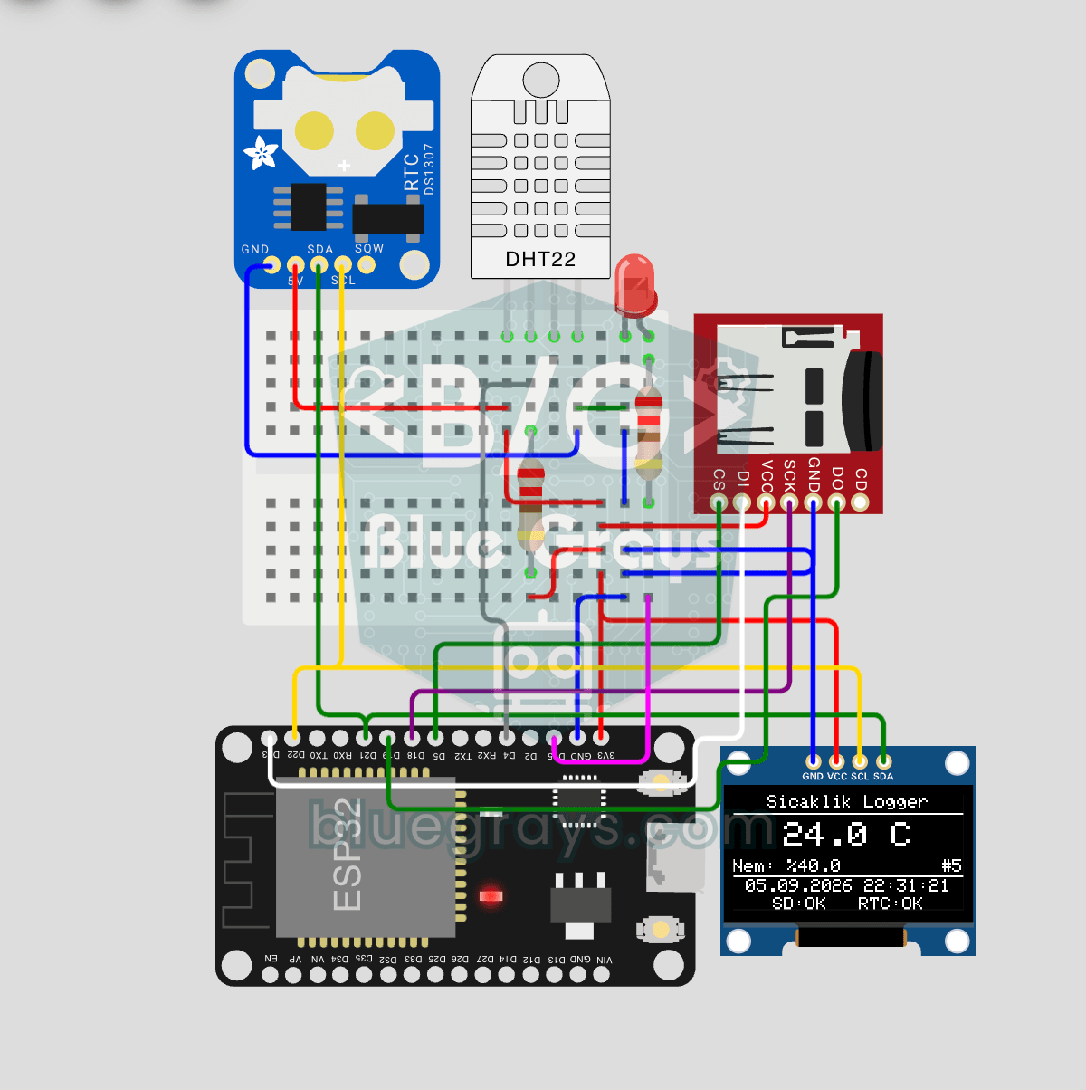
ESP32 Temperature Data Logger (DHT22 + DS1307 RTC + microSD + OLED)
Build a timestamped temperature logger with ESP32! Read DHT22 temperature/humidity every minute, get real-world time from DS1307 RTC, and log to microSD card as CSV. The OLED displays live temperature (large font), humidity percentage, timestamp, and log counter. The /temp_log.csv file on the SD card opens in Excel, Google Sheets, or Python pandas for analysis — perfect for greenhouse monitoring, home/room temperature tracking, laboratory data collection, food storage conditions, or beehiv
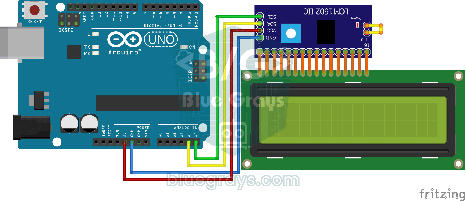
Using LCD Screen with I2C
Give your Arduino its own screen and make it write its first message. The two-line LCD screen hooks up with just a few wires; a greeting appears on the top line, then a second message on the bottom li
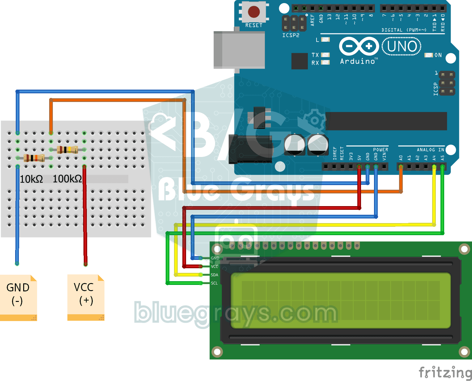
Digital Voltmeter with LCD Display
Find out how much voltage a battery or power adapter gives with a meter you built yourself. A divider made of two resistors brings high voltage down to a level the board can read, and the Arduino calc