
Electronics Calculator App: 18 Tools and Worked Examples
Electronics calculator app guide: what the 18 BlueGrays tools do, which 7 are free, and worked examples for color codes, LED resistors, 555 and battery life.
Yes, there is an electronics calculator app for your phone that handles these jobs: the Tools screen in BlueGrays groups 18 tools into four sections: Resistors, Calculators, Capacitors and inductors and Reference. Seven of them are free (Color code, SMD code, Ohm's law, LED resistor, Capacitor code, Inductor code, LED voltages) and 11 are Premium. Nine of the Premium tools also open for free users as a Sample calculation: you see the tool working with ready-made values, and you need Premium to enter your own. In short, reading a resistor's value from its colors, finding how many ohms to put in front of an LED or working out a current with Ohm's law costs nothing, while design calculations such as the voltage divider, the 555, battery life and RC timing sit on the Premium side.
We have covered the theory of Ohm's law, series and parallel connections and capacitors in separate posts: Ohm's law, series and parallel resistor calculation and what is a capacitor. This post doesn't repeat the theory; it is about the tools themselves. First we look at how the screen is organized and at the full list of 18 tools, then we work through seven examples step by step, with the numbers the app will show you: color code, SMD code, LED resistor, voltage divider, 555 square wave, ESP32 battery life and RC time constant. At the end you'll find saved calculations, the pinout and transistor references, a lesson-by-lesson tool map and an "I have X, which tool do I open?" list.
Where is the Tools screen and how is it organized?
The Tools screen opens when you tap the Tools tab in the app's bottom bar. At the top is a search box reading Search tools: resistor, LED, 555…, below it a Recently used strip for the tools you have opened before, and then the tool cards in four sections. Premium tools carry a small Premium label on their card, so you can tell which ones are free without opening them. At the very bottom of the list there is a Missing a tool? card with a Suggest button. The order of the sections follows the questions you ask at the workbench: first identify the part in your hand, then calculate the circuit, and finally look something up. Here is what each section contains:
| Section | Free tools | Premium tools | When do you open it? |
|---|---|---|---|
| Resistors | Color code, SMD code | Series / parallel, Standard value | When identifying a resistor or building an unavailable value from two resistors |
| Calculators | Ohm's law, LED resistor | Voltage divider, 555 timer, Battery life, Op-amp gain | When designing a circuit: current, resistance, frequency, battery runtime |
| Capacitors and inductors | Capacitor code, Inductor code | Series / parallel C, RC time constant | When reading the code on a capacitor or inductor, or working out charge time |
| Reference | LED voltages | Transistors, Pinout, Logic gates | When you need a pin order, a board's pins or a truth table |
18 electronics tools: what they calculate and which are free
| Tool | What it calculates or shows | Access | Example |
|---|---|---|---|
| Color code | Value, tolerance and range of 4, 5 and 6-band resistors; colors from a value in reverse | Free | Red-red-brown-gold = 220 Ω ±5% |
| SMD code | 3- and 4-digit, R-notation and EIA-96 SMD resistor codes | Free | 472 = 4.7 kΩ; 01C = 10 kΩ |
| Series / parallel | Total of series, parallel or mixed resistors; voltage, current and power of each, step by step | Premium, sample open | 220 + 330 + 470 Ω = 1020 Ω; 4.9 mA at 5 V |
| Standard value | Nearest E12, E24 or E96 value and two-resistor series / parallel pairs | Premium, sample open | 5 kΩ: 4.7 kΩ + 330 Ω or 10 kΩ ∥ 10 kΩ |
| Ohm's law | Enter two of V, I, R and P; it gives the other two and the resistor power rating | Free | 5 V, 220 Ω → 22.7 mA, 114 mW, at least 1/4 W |
| LED resistor | Standard resistor, actual current and resistor power from LED color, supply, current and LEDs in series | Free | 5 V, red, 15 mA → 220 Ω |
| Voltage divider | Divider output, or ready-made R1 / R2 pairs for a target voltage | Premium, sample open | 5 V, 10 kΩ / 20 kΩ → 3.33 V |
| 555 timer | Frequency, period and duty cycle for a square wave; pulse length for a single pulse | Premium, sample open | 1 kΩ, 68 kΩ, 10 µF → ≈1.05 Hz |
| Battery life | Average current and estimated runtime with an awake / sleep cycle | Premium, sample open | 2600 mAh, ESP32 deep sleep → ≈136 days |
| Op-amp gain | Gain, dB, output voltage and clipping warning for inverting and non-inverting amplifiers | Premium, sample open | Non-inverting, 100 kΩ / 10 kΩ → ×11 (20.8 dB) |
| Capacitor code | Capacitor codes such as 104, 103K, 4n7 and the tolerance letter | Free | 104 = 100 nF |
| Series / parallel C | Total capacitance and voltage rating of series or parallel capacitors | Premium, sample open | 100 nF + 100 nF + 10 µF in parallel = 10.2 µF |
| RC time constant | Time constant τ, charge / discharge table and filter cutoff frequency | Premium, sample open | 10 kΩ × 100 µF → τ = 1 s |
| Inductor code | Inductor codes such as 101, 4R7, 47N | Free | 101 = 100 µH |
| LED voltages | Typical and maximum LED voltage and maximum current by color | Free | Red ≈1.85 V, blue ≈3.3 V |
| Transistors | Pin order, limits and equivalents of transistors and MOSFETs | Premium | BC547: CBE, 45 V, 100 mA |
| Pinout | Board pins with Analog, PWM, I2C, SPI, UART, DAC and Caution filters | Premium | On the ESP32, ADC2 pins can't be read while Wi-Fi is on |
| Logic gates | Truth tables and IC numbers for AND, OR, NOT, NAND, NOR, XOR, XNOR | Premium, sample open | NAND: 7400 · 4011 |
Example 1: reading a 220 Ω resistor with the color code tool
- Open the Color code tool, stay on the Colors to value tab and choose 4 bands.
- Hold the resistor with the gold band on the right and enter the colors from left to right: band 1 red (2), band 2 red (2), band 3 brown (multiplier ×10), band 4 gold (tolerance 5%).
- The tool returns 22 × 10 = 220 Ω ±5% and also shows the tolerance range: 209–231 Ω.
- On the same screen you see which standard series contain the value: 220 Ω is a very common value found in the E6, E12 and E24 series.
- To be sure, measure the resistor on your multimeter's ohms range; a reading between 209 and 231 Ω confirms you read the colors correctly.
It also works the other way: type a value such as 220, 4k7, 4,7k or 1M2 into the Value to colors tab and the tool draws the bands. If you enter a value that can't be written with 4 bands, for example 4.99 kΩ, it shows the nearest value and tells you to pick 5 bands for the exact one. Five-band resistors have three digits, a multiplier and a tolerance band; a six-band resistor adds a temperature coefficient band at the end, which the tool shows in ppm/K. Colors can be misleading in dim light; brown and red, or orange and red, are often confused. That's why measuring with a multimeter is the most reliable check for a critical part.
Example 2: SMD codes 472, 1002 and 01C
| Code | Format | How to read it | Value |
|---|---|---|---|
| 472 | 3 digits, usually 5% | 47 and 2 zeros: 47 × 10² Ω | 4.7 kΩ |
| 1002 | 4 digits, usually 1% | 100 and 2 zeros: 100 × 10² Ω | 10 kΩ |
| 01C | EIA-96, 1% | Value number 01 is 100, letter C is ×100 | 10 kΩ |
| 4R7 | R as decimal point | R is the decimal point | 4.7 Ω |
| 68X | EIA-96, 1% | Value number 68 is 499, letter X is ×0.1 | 49.9 Ω |
Just type the code printed on the part into the SMD code tool, letters and digits exactly as they appear; the tool recognizes the format by itself and explains it under How to read it. The most common confusion is with EIA-96 codes such as 01C: the 01 here is not a value but a position number in the 1% E96 series. Value number 1 is 100 and the letter C means ×100, so the result is 10 kΩ. In other words, 1002 and 01C are the same resistor written in two different formats. Two more free tools work the same way for capacitors and inductors: Capacitor code decodes 104 as 10 × 10⁴ pF = 100 nF and reads the K in a code like 103K as a 10% tolerance; Inductor code gives 101 as 100 µH and 4R7 as 4.7 µH.
Example 3: a red LED at 5 V and 15 mA
- Open the LED resistor tool and pick red as the LED color. The tool uses a typical forward voltage of about 1.85 V for a red LED.
- Set Supply to 5 V (an Arduino Uno pin) and Current to 15 mA. You are using a single LED, so leave LEDs in series at 1.
- The tool works out the voltage left for the resistor: 5 − 1.85 = 3.15 V. The calculated resistance is 3.15 V / 15 mA = 210 Ω.
- 210 Ω is not a value you can buy, so the tool suggests the next standard value up: 220 Ω. That's the red-red-brown resistor from the first example, and the tool draws its bands too.
- With 220 Ω the actual current is 3.15 / 220 ≈ 14.3 mA. If the LED voltage is at its upper limit (2.5 V for red), the current drops to about 11.4 mA; the LED still lights up nicely.
- The power dissipated in the resistor is about 45 mW. The tool recommends at least 1/8 W with a twofold margin; the ordinary 1/4 W resistor in your kit is more than enough.
Example 4: a ready-made resistor pair to drop 5 V to 3.3 V
Say you want to connect the output of a 5 V sensor to the 3.3 V input of an ESP32 or a Pico. The Voltage divider tool has two modes: in Find output you enter R1 and R2 and the tool gives the output, current, ratio and total power; in Find resistors you enter the input and the target output and the tool suggests Ready-made pairs of standard resistors. The sample calculation opens with a 5 V input, 10 kΩ on top and 20 kΩ at the bottom: the output is 5 × 20 / 30 = 3.33 V and the divider draws about 0.17 mA. In Find resistors mode, when you enter 3.3 as the target and switch between the E12, E24 and E96 series, the suggestions change; here are the results for the first two series:
| Series or mode | R1 (top) | R2 (bottom) | Output | Off target |
|---|---|---|---|---|
| E12, ready-made pair | 1.2 kΩ | 2.2 kΩ | 3.24 V | −2.0% |
| E12, ready-made pair | 12 kΩ | 22 kΩ | 3.24 V | −2.0% |
| E24, ready-made pair | 4.7 kΩ | 9.1 kΩ | 3.30 V | −0.09% |
| E24, ready-made pair | 47 kΩ | 91 kΩ | 3.30 V | −0.09% |
| Find output (sample) | 10 kΩ | 20 kΩ | 3.33 V | +1.0% |
Tap a pair and its values move into the calculation, where you see the current and power. When choosing between pairs with the same ratio, look at the current: a 4.7 kΩ / 9.1 kΩ divider draws about 0.36 mA from 5 V, while 47 kΩ / 91 kΩ draws 0.036 mA. Small resistors waste current, and very large ones make the analog reading more sensitive. That's why the app's note tells you to keep R1 + R2 usually between 10 and 100 kΩ, and reminds you that a divider output is not a power supply: connect a motor, relay or LED and the voltage drops. A divider is for ADC inputs and for shifting 5 V down to 3.3 V. To see the same idea in practice, look at the free Measuring Light Intensity with an LDR project: the LDR and a fixed resistor form a divider there too, and the Arduino reads the voltage in the middle.
Example 5: a 1 Hz square wave with the 555
The 555 timer tool has Square wave and Single pulse modes. For a square wave you enter three values: R1 (between pin 7 and VCC), R2 (between pin 6 and pin 7) and C (between pin 6 and GND). The sample calculation opens with R1 = 1 kΩ, R2 = 68 kΩ and C = 10 µF. The frequency is f ≈ 1.44 / ((R1 + 2·R2) · C): 1.44 / (137 kΩ × 10 µF) = 1.44 / 1.37 s ≈ 1.05 Hz. The tool also shows the times separately: HIGH time 0.693 × (R1 + R2) × C ≈ 0.478 s, LOW time 0.693 × R2 × C ≈ 0.471 s, period ≈ 0.95 s. The duty cycle is the HIGH time divided by the period: 0.478 / 0.95 ≈ 50.4%. The LED preview on screen really blinks at this speed; as the frequency rises, the tool notes that the eye can no longer see the blinking and the LED looks as bright as the duty cycle. A faster example: with R1 = 1 kΩ, R2 = 10 kΩ and C = 100 nF the tool shows about 687 Hz and a 52.4% duty cycle, an audible tone on a buzzer. In Single pulse mode the length is t = 1.1 × R × C: with 100 kΩ and 10 µF that is 1.1 seconds. For the IC's pins and how to build the circuit, see the 555 timer IC post.
Example 6: ESP32 battery life with deep sleep
- In the Battery life tool, pick an 18650 as the battery (2600 mAh). The presets also include CR2032, 9 V, LiPo and 2 × AA, and you can type the capacity by hand.
- Choose ESP32 · deep sleep as the current profile: the board stays awake for 5 seconds drawing 80 mA, draws 10 µA in sleep, and the cycle repeats every 600 seconds (10 minutes).
- Work out the average current: (80 mA × 5 s + 0.010 mA × 595 s) / 600 s = (400 + 5.95) / 600 ≈ 0.677 mA.
- Find the usable capacity: the tool counts 85% of the capacity to allow for battery aging, cold weather and regulator loss: 2600 × 0.85 = 2210 mAh.
- Find the runtime: 2210 / 0.677 ≈ 3266 hours, or about 136 days (4.5 months).
| Scenario | While awake | Cycle | Average current | Estimated runtime (2600 mAh) |
|---|---|---|---|---|
| ESP32 · deep sleep (preset) | 80 mA, 5 s | 600 s | ≈0.68 mA | ≈136 days |
| Awake time cut to 1 s | 80 mA, 1 s | 600 s | ≈0.14 mA | ≈642 days (≈1.8 years) |
| Awake 5 s, once an hour | 80 mA, 5 s | 3600 s | ≈0.12 mA | ≈760 days (≈2.1 years) |
| ESP32 · always on | 80 mA | continuous | 80 mA | ≈28 hours |
| Arduino Uno, always on | 45 mA | continuous | 45 mA | ≈49 hours |
The lesson of the table is clear: in the preset, about 98.5% of the energy is used while awake, and the tool says so plainly: "Most of the energy is used while awake". Cutting the sleep current from 10 µA to 5 µA barely changes the result, while cutting the awake time from 5 seconds to 1 second makes the battery last almost five times longer. The tool draws the current profile on a two-cycle logarithmic chart, so you see the short but high wake-up peak and the long but low sleep floor at the same time. One caution: boards like the Arduino Uno draw milliamps even in sleep because of their regulator and power LED, so putting an Uno to sleep doesn't stretch battery life the way it does on an ESP32. The Premium ESP32 Deep Sleep — Battery Saving (OLED + RTC RAM Counter) project in the app shows this scenario in code; for ways to power a board from batteries, see running an Arduino on batteries.
Example 7: RC time constant and cutoff frequency
In the RC time constant tool you enter a resistor and a capacitor and choose the Charge or Discharge curve. For the 10 kΩ and 100 µF of the sample calculation, τ = R × C = 10,000 Ω × 0.0001 F = 1 second. The tool builds a table: at 1τ (1 s) the capacitor reaches 63% of the supply voltage, at 2τ 86%, at 3τ 95%; at 5τ (5 s) it counts as full at 99.3%. The time to reach 50% is 0.69 seconds. Used as a low-pass filter, the same RC has a cutoff frequency of fc = 1 / (2π × R × C) ≈ 0.16 Hz. Change the capacitor to 100 nF and τ drops to 1 millisecond with a cutoff of about 159 Hz, a more useful range for smoothing a PWM output or a bouncing button. You can type values like 100n, 4u7 or 22p; if the capacitor has a code such as 104 printed on it, decode it first with the Capacitor code tool. To reduce several parallel capacitors to a single value, use the Series / parallel C tool.
Saved calculations, Recently used, search and Suggest a tool
- Saved calculations (Premium): the Save button below a tool stores the calculation with its inputs in your account; it isn't lost if you change phones and shows up on all your devices. Tap a saved entry and the tool reopens with the same values; remove the ones you don't need with Delete. With a free account, tapping Save opens the Premium overview.
- Share: sends the result as a short text by message or through another app, a quick way to pass the resistor you calculated to your lab partner.
- Recently used: the last six tools you opened sit in a strip at the top of the screen, so you get back to your favorite tool in one tap.
- Search: typing into the Search tools: resistor, LED, 555… box filters the tools and shows how many results were found. If nothing matches, the screen points you to the suggestion card.
- Suggest a tool: tap Suggest on the Missing a tool? card at the end of the list and briefly write which calculator or table would help you. The examples the app gives are "7-segment display pins" and "buck converter calculator".
Pinout and Transistors: reference tables for the workbench
The Pinout tool shows a board's pins on a drawing of the board. Besides the Arduino Uno, ESP32 and Raspberry Pi Pico, the list includes boards from the same families: Arduino Nano, Mega and Leonardo, ESP32-S3 and C3 SuperMini, Raspberry Pi 4 and Zero 2 W. The filters at the top highlight Analog, PWM, I2C, SPI, UART, DAC and Caution pins one group at a time. Tap a pin and the SELECTED PIN card opens with its logic voltage, its current limit (20 mA recommended on the Uno, 40 mA at most; 4 mA by default on the Pico, up to 12 mA) and an explanation of what that function is for; you can also copy sample code for the pin. The notes prevent practical mistakes: on the ESP32, ADC2 pins can't do analog reads while Wi-Fi is on; on the Pico, analog input only works on GP26, GP27 and GP28; and a pin used for I2C can't do analog reads at the same time. For every Uno pin there is also the Arduino Uno pinout post.
The Transistors tool lists the most widely used NPN and PNP transistors and MOSFETs; type BC547, TIP120 or IRLZ44N into the search box. Each card shows the pin order (printed face toward you, legs down, left to right), the voltage and current limits and an Equivalent line. That line points to an important trap: the BC547 and 2N3904 can replace each other, but their pin orders differ (CBE on the BC547, EBC on the 2N3904); swap the part without checking the circuit and the transistor ends up reversed. The two other tools in the Reference section are useful in class too: in Logic gates you try AND, OR, NOT, NAND, NOR, XOR and XNOR by tapping the A and B inputs and see the truth table and IC numbers (7400 and 4011 for NAND, for example). The free LED voltages table lists the typical and maximum voltage and the maximum current for each color. For the theory, see what is a transistor and logic gates.
For students and teachers: which tool for which lesson?
The tools don't replace a textbook, but they are a good second step for checking a calculation done by hand. Say you are teaching Ohm's law to a class of 24: students do the calculation on paper first, then compare it with the free tool, and finally measure with a multimeter. For a lesson plan that builds this three-step flow in detail, see the Ohm's law activity post. For the tools marked "sample" in the table, a free account only shows the ready-made example; if students need to try different values, either project a Premium account on the board or build the task around the sample values.
| Topic | Tool | Access | Short classroom task |
|---|---|---|---|
| Ohm's law, current and power | Ohm's law | Free | Find the current and power for 5 V and 220 Ω, then measure with a multimeter |
| Identifying resistors | Color code, SMD code | Free | Pull 5 resistors from the box, read the value from the colors, check with the tool |
| LED circuits | LED resistor, LED voltages | Free | Pick a resistor for a red and a blue LED at 5 V, explain the difference |
| Series and parallel | Series / parallel | Sample | In a 220 + 330 + 470 Ω chain, guess which resistor drops the most voltage |
| Analog input, sensors | Voltage divider | Sample | Find the output of a 10 kΩ / 20 kΩ divider on paper, compare with the tool |
| Timing, oscillators | 555 timer, RC time constant | Sample | In a 1 Hz flasher, what happens to the frequency if C is doubled? |
| Energy and batteries | Battery life | Sample | How many more days does the battery last with 1 s awake instead of 5 s? |
| Digital logic | Logic gates | Sample | Fill in the NAND table and explain how to build a NOT gate from NAND |
| Boards and wiring | Pinout, Transistors | Premium | Find which of the project's pins is PWM and which is I2C |
Tool picker: I have X, which tool do I open?
- A resistor with colored bands → Color code.
- A tiny SMD resistor with a 3–4 character code → SMD code.
- A capacitor marked 104, 473 or 2n2 → Capacitor code; combining several → Series / parallel C.
- An inductor marked 101 or 4R7 → Inductor code.
- An LED and a supply voltage → LED resistor; wondering how many volts an LED color needs → LED voltages.
- A calculated value you can't buy, for example 5 kΩ → Standard value: in E12, 4.7 kΩ + 330 Ω in series (5.03 kΩ) or 10 kΩ ∥ 10 kΩ in parallel (exactly 5 kΩ).
- Two known quantities, for example voltage and resistance → Ohm's law; a chain of several resistors → Series / parallel.
- A 5 V signal and a 3.3 V board → Voltage divider.
- A 555 IC and a few resistors and capacitors → 555 timer; the charge time of a single capacitor → RC time constant.
- A battery-powered ESP32 project → Battery life.
- A weak sensor signal that needs amplifying → Op-amp gain (the theory is in what is an op-amp).
- A transistor you don't recognize → Transistors; a board where you don't know what goes on which pin → Pinout.
- A logic IC such as the 7400 → Logic gates.
To sum up: everyday calculations such as reading colors and codes, Ohm's law and LED resistors are ready on your phone with the free tools; design calculations such as the voltage divider, the 555, battery life and RC timing can be explored in the sample first and, if you need them, done with your own values with Premium. A calculation alone doesn't make a circuit work; you still have to try the result on a breadboard. Open the Tools screen in the BlueGrays app, repeat one of the examples in this post with your own parts, then build the free LED Blink or Traffic Light project with the same resistors and LEDs. If you want to control your circuit from your phone, try BlueGrays IoT under Workshop › My devices › Add new device. You pick one of 8 ready templates for an ESP32 or Raspberry Pi Pico W. Ohmi prepares the code with your device key, and you upload it once from Arduino IDE with the BlueGraysIoT library. Your first device is free: 1 device, a chart for 1 value and 24 hours of history. For the steps, see the guide to controlling an ESP32 from your phone.
Frequently asked questions
Is there an app that calculates resistor and LED values on your phone?
Yes. The Tools screen in BlueGrays has 18 electronics tools; Color code, SMD code, Ohm's law, LED resistor, Capacitor code, Inductor code and LED voltages are free. The app runs on iOS and Android in 10 languages.
What resistor do I need for an LED at 5 V?
For a red LED (about 1.85 V) at 15 mA the calculation is (5 − 1.85) / 0.015 = 210 Ω; the next standard value is 220 Ω. Blue and white LEDs are around 3.3 V, so 120 Ω is enough for the same current. The LED resistor tool does this by color and also shows the actual current.
What does 01C mean on an SMD resistor?
01C is an EIA-96 code: 01 is the 1st value in the 1% E96 series (100) and the letter C is a ×100 multiplier. The result is 10 kΩ, the same resistor as the code 1002. The SMD code tool recognizes this format automatically.
How do you calculate the frequency of a 555 timer?
In a square wave (astable) circuit you use f ≈ 1.44 / ((R1 + 2·R2) · C). For R1 = 1 kΩ, R2 = 68 kΩ and C = 10 µF the frequency is about 1.05 Hz with a duty cycle of about 50.4%. The 555 timer tool also gives the HIGH and LOW times separately.
How long will an ESP32 run on a battery?
It depends on the awake and sleep times. With a 2600 mAh 18650, an ESP32 that draws 80 mA for 5 seconds every 10 minutes and sleeps at 10 µA the rest of the time averages 0.68 mA and runs for about 136 days; left always on, it lasts about 28 hours. The Battery life tool counts 85% of the capacity as usable.
Can I try the Premium electronics tools for free?
Nine of the Premium tools open on a free account as a Sample calculation with ready-made values; you see the result and the explanations but can't enter your own values. Transistors and Pinout have no sample view. Saving calculations (Saved calculations) is also a Premium feature.
Projects to build after reading this
See all projects
LED Blink
The very first hello of electronics: switching a single LED on and off. The Arduino turns the LED on and off at short intervals, so the light blinks quickly. You see in the simplest way how the board

Traffic Light
A tiny copy of the traffic light you see on the road every day. Red stays on for two seconds, yellow flashes for a moment, green stays on for two seconds, then it goes back to red through yellow again

Measuring Light Intensity with an LDR
Want to see how bright your room is as a number? The LDR, a small part that reacts to light, measures the light around it, and the Arduino writes the value to your computer screen every half second. C

Night Light with Ldr
A little night light that turns on by itself when it gets dark and goes off when morning comes. A light sensor measures how bright the room is, and the Arduino switches the LED on when it is dark enou
Frequency Setting with Buzzer
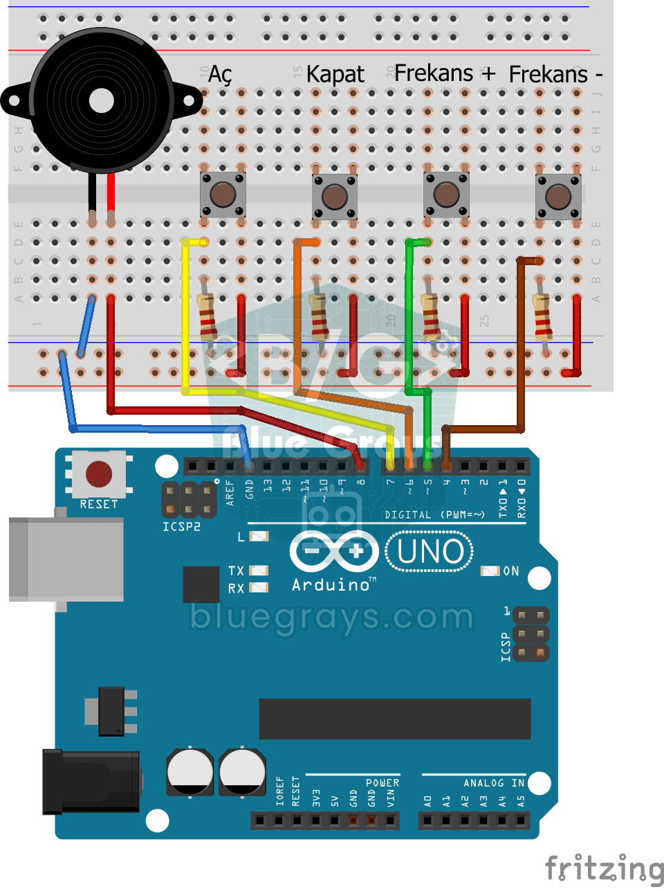
You control the sound of a buzzer with four buttons: one starts the sound, one silences it, and the other two make it higher or lower. Hold the up or down button and the pitch changes step by step, sl

ESP32 Deep Sleep — Battery Saving (OLED + RTC RAM Counter)
The ESP32's Deep Sleep mode reduces current consumption to ~10 µA by shutting down the CPU and most peripherals, making it critical for battery-powered IoT devices. In this project, we use three different wake-up sources: a timer (15 seconds), an external pin (EXT0 — button GPIO 33), and touch (T0/GPIO 4). Variables marked with RTC_DATA_ATTR are preserved during deep sleep—the boot counter, timer wake counter, and button wake counter are continuously tracked. On each wake-up, the SSD1306 OLED
Using an RGB LED
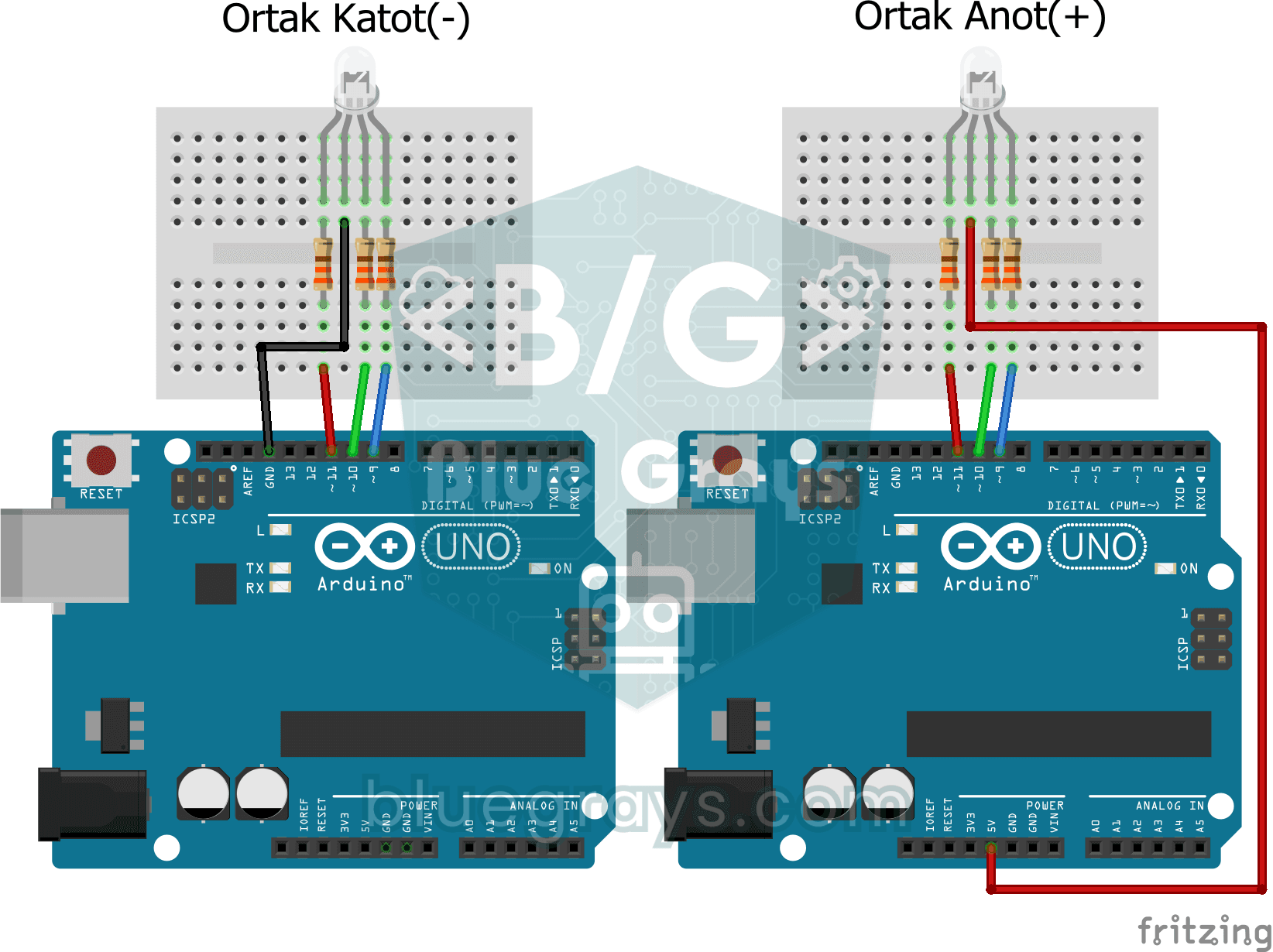
Three colours hide inside a single LED: the RGB LED lights up red, then green, then blue, each colour on for half a second and off for half a second, before the cycle starts again. All you need is one
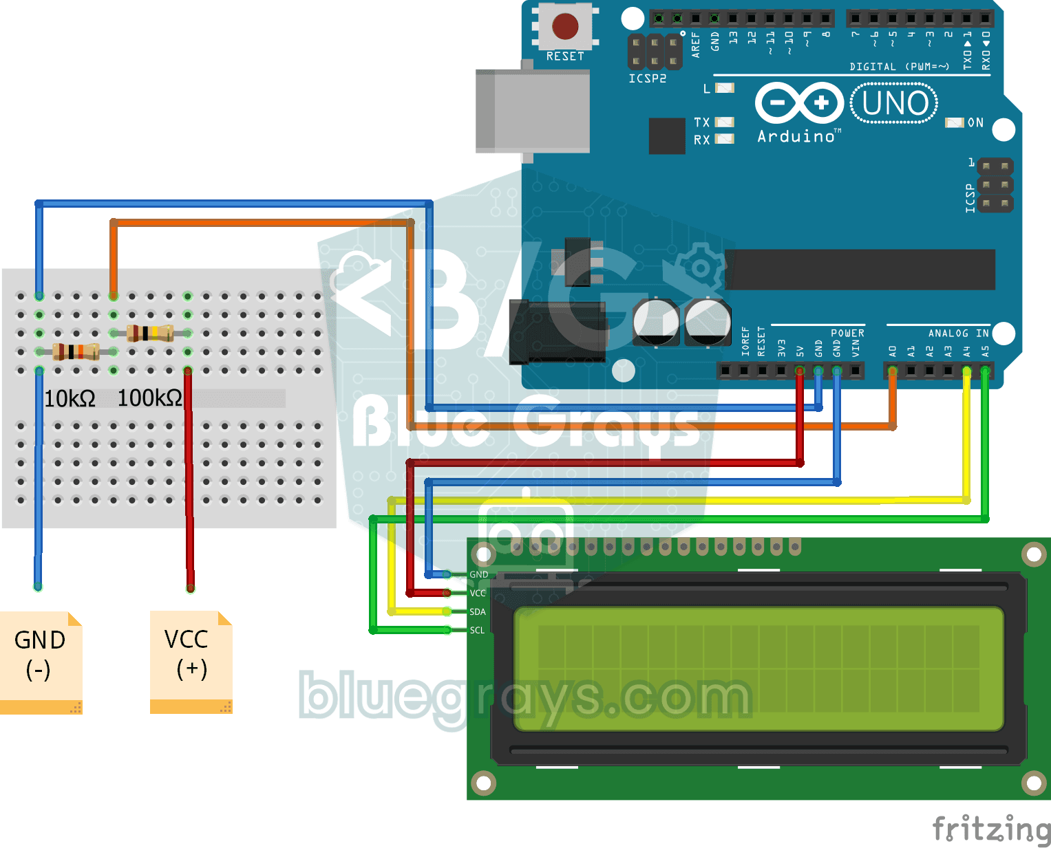
Digital Voltmeter with LCD Display
Find out how much voltage a battery or power adapter gives with a meter you built yourself. A divider made of two resistors brings high voltage down to a level the board can read, and the Arduino calc