
What Is an Op-Amp? Gain Formulas, LM358 and Arduino Circuits
What is an op-amp and how does it work? Inverting and non-inverting gain formulas, buffer, comparator, LM358 and LM741 pinouts, single supply and Arduino ADC.
An op-amp (operational amplifier) is a small integrated circuit, usually with eight pins, that multiplies the tiny voltage difference between its two inputs by hundreds of thousands. That is the short answer to what is an op-amp, but such a huge gain on its own isn't very useful. The magic happens when a few resistors feed part of the output back to the input: the op-amp then becomes a precise amplifier whose gain is set by a resistor ratio, a buffer, a comparator or a filter. From microphone preamps to pulse sensors, from scale modules to sound cards, there's an op-amp in almost every corner of analog electronics.
When you work with Arduino, the main reason you need an op-amp is this: many sensors produce signals in the millivolt range, while the Arduino Uno's ADC can only resolve steps of 4.88 mV. A K-type thermocouple produces just 4.1 mV at 100 °C; connect it directly and the Arduino barely notices that temperature. In this guide you'll learn the ideal op-amp rules, the inverting and non-inverting gain formulas, the voltage follower, the comparator, the LM358 and LM741 pinouts, single-supply operation, and how to match microphone and thermocouple signals to the ADC of an Arduino, ESP32 and Raspberry Pi Pico, all with real values.
What is an op-amp and how does it work?
An op-amp has five basic terminals: the non-inverting input (+), the inverting input (−), the output and two supply pins (V+ and V−). It only looks at the difference between its two inputs and multiplies it by its open-loop gain (A): Vout = A × (V+ − V−). On the LM358, A is typically 100,000 (100 dB). That means a difference of just 0.1 mV between the inputs asks for 10 V at the output; but the output can't go beyond the supply, so the output of an op-amp without feedback almost always sticks to one of the rails, in other words it saturates. That behaviour is useful in comparator circuits. To build an amplifier, part of the output is fed back to the inverting input through resistors; this is called negative feedback, and from then on the gain is set by the resistors, not by the op-amp.
| Property | Ideal op-amp | LM358 (typical) | LM741 (typical) |
|---|---|---|---|
| Open-loop gain | Infinite | 100,000 (100 dB) | 200,000 (106 dB) |
| Input (bias) current | 0 | 20 nA | 80 nA |
| Input offset voltage | 0 | 3 mV (7 mV max) | 1 mV (5 mV max) |
| Gain-bandwidth product (GBW) | Infinite | 0.7 MHz | About 1 MHz |
| Slew rate | Infinite | 0.3 V/µs | 0.5 V/µs |
| Output swing | Up to the rails | Close to 0 V, V+ − 1.5 V at the top | 1–3 V inside each rail |
| Supply | Unlimited | 3–30 V single or ±1.5–±15 V | ±10–±18 V recommended (LM741C) |
Ideal op-amp rules: virtual short and zero input current
- Rule 1 – The inputs draw no current: an ideal op-amp has infinite input resistance, so no current flows into the + and − pins. In reality the LM358 draws about 20 nA, which causes an error of only 2 mV even across a 100 kΩ resistor.
- Rule 2 – Virtual short: with negative feedback, the output does whatever it takes to bring both inputs to the same voltage, so V+ = V−. The inputs aren't connected to each other, but they sit at the same voltage.
- Practical rule – The output can't exceed the supply: even if the formula asks for 12 V, an op-amp powered from 5 V can only go up to the supply, and an LM358 only to about 3.5 V. An output stuck at that limit is called clipping or saturation.
With these rules you can solve almost any op-amp circuit on paper in a few lines: first find the voltage at the + input, assume the − input sits at the same voltage, then write the currents through the resistors with Ohm's law. Because the current can't enter the input, it has to flow through the feedback resistor, and that gives you the output voltage. Remember: the second rule only holds when there is negative feedback. In circuits without feedback, such as a comparator, the inputs are at different voltages and the output sits at one of the rails. If you want to brush up on current and voltage calculations, take a look at the Ohm's law guide.
Non-inverting amplifier: gain formula and example
In a non-inverting amplifier the signal goes straight to the + input. A feedback resistor (Rf) runs from the output to the − input, and a ground resistor (Rg) from the − input to GND. These two resistors form a voltage divider: the voltage at the − input is Vout × Rg / (Rf + Rg). By the virtual short rule this equals the input, which gives the formula Vout = Vin × (1 + Rf / Rg). With Rf = 10 kΩ and Rg = 1 kΩ the gain is 11, so a 100 mV signal becomes 1.1 V. The output moves in the same direction as the input, the gain never drops below 1 and the input resistance of the circuit is very high, so it doesn't load the sensor.
| Rf | Rg (Rin in the inverting circuit) | Non-inverting gain | Inverting gain |
|---|---|---|---|
| 10 kΩ | 10 kΩ | 2 (6.0 dB) | −1 (0 dB) |
| 47 kΩ | 10 kΩ | 5.7 (15.1 dB) | −4.7 (13.4 dB) |
| 10 kΩ | 1 kΩ | 11 (20.8 dB) | −10 (20 dB) |
| 100 kΩ | 4.7 kΩ | 22.3 (27.0 dB) | −21.3 (26.6 dB) |
| 100 kΩ | 1 kΩ | 101 (40.1 dB) | −100 (40 dB) |
Inverting amplifier and virtual ground
In an inverting amplifier the + input is tied to GND and the signal reaches the − input through a resistor Rin; Rf again sits between the output and the − input. By the virtual short rule the − input is also at 0 V, yet it isn't connected to GND; this is called a virtual ground. The current Vin / Rin flowing through Rin can't enter the input, so it must flow through Rf, and the output becomes Vout = −(Rf / Rin) × Vin. With Rin = 10 kΩ and Rf = 47 kΩ the gain is −4.7: a 0.5 V input gives a −2.35 V output. The minus sign means the signal is inverted. The input resistance of the circuit is roughly Rin, so it can load a sensor with a high internal resistance.
A nice use of the inverting topology is the summing amplifier (mixer): connect several signals to the − input, each through its own resistor, and the output becomes the inverted weighted sum of those signals. In a single-supply Arduino circuit, however, you have to tie the + input of an inverting amplifier to a reference, such as half the supply, instead of GND; otherwise positive inputs ask for a negative output and the output sticks at 0 V. In that case the formula becomes Vout = Vref − (Rf / Rin) × (Vin − Vref).
Voltage follower (buffer): the most useful circuit with a gain of 1
Connect the output straight to the − input and feed the signal to the + input, and you get a voltage follower (buffer). Since Rf is zero and Rg is infinite, the gain is exactly 1 and Vout = Vin. Why is a circuit that doesn't amplify useful? Because it draws almost no current from its input yet can deliver milliamps at its output; it turns a high-impedance source into a low-impedance one. The ATmega328P datasheet says its ADC works best with a source impedance of 10 kΩ or less. A 100 kΩ + 100 kΩ voltage divider behaves like a 50 kΩ source, and when the Arduino switches between channels the reading can drift by a few steps. Put a follower after the divider and the problem disappears.
Other classic uses of the follower: smoothing a PWM signal with an RC filter and buffering it to make a simple DAC, sharing a reference voltage taken from a potentiometer between several circuits, and driving a long cable from an op-amp output instead of a weak sensor output. On a single supply the LM358 can follow down to 0 V, but with a 5 V supply it can't go above about 3.5 V; if you want to buffer the full 0–5 V range, choose a rail-to-rail op-amp.
The op-amp as a comparator
Used without feedback, an op-amp becomes a switch that compares two voltages: if the + input is even a few millivolts higher than the − input, the output goes to the top limit, and if it's lower, the output goes to 0 V. A night light without a microcontroller is a nice example. Connect the midpoint of a divider built in the order 5V, 10 kΩ, LDR, GND to the + input, and the wiper of a potentiometer to the − input. In the dark the LDR's resistance rises, the midpoint voltage crosses the threshold you set with the pot, and an LED connected to the output through 330 Ω turns on. The LM358 is good enough for this job but it's slow: with a slew rate of 0.3 V/µs, the output needs more than 10 µs to rise from 0 to 3.5 V.
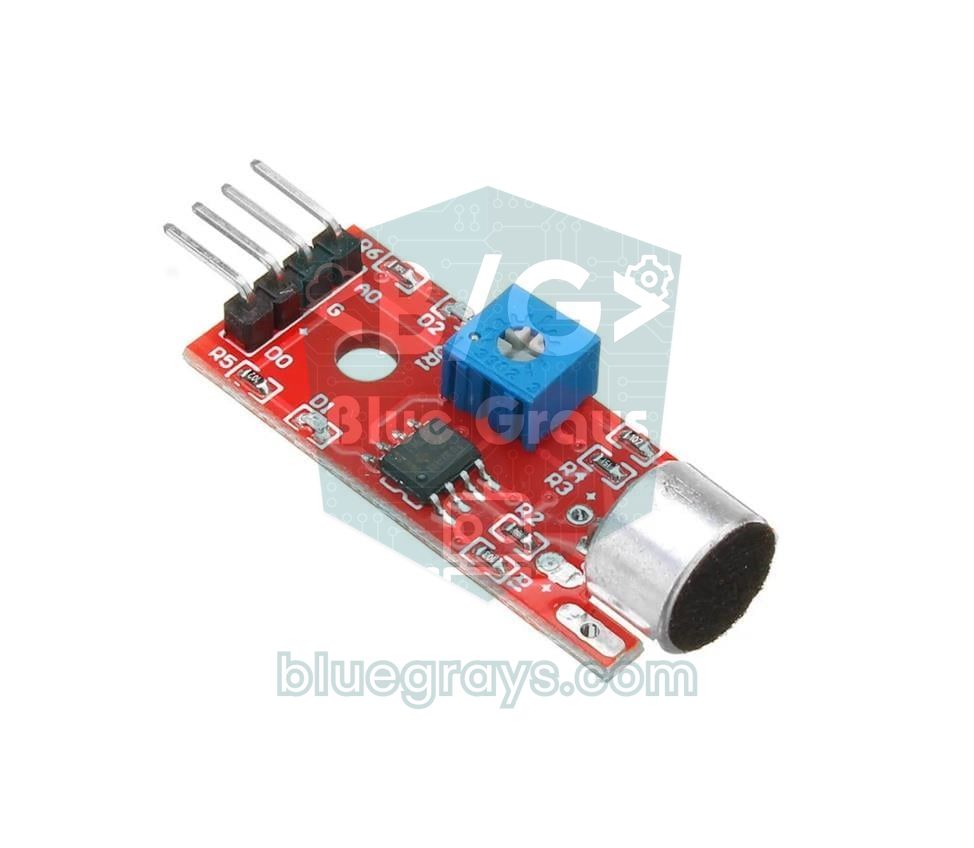
For jobs that need fast, clean transitions, a real comparator such as the LM393 is used. The LM393 has the same pinout as the LM358, but its output is open-collector: it can only pull the output down to GND, and it needs a pull-up resistor, such as 10 kΩ, between the output and the supply to go high. This lets you tie the pull-up to 3.3 V and safely feed the output of a comparator powered from 5 V into an ESP32 or Pico. The small chip next to the blue trimmer on the KY-038 sound sensor and on soil moisture, rain, flame and gas modules is almost always an LM393.
With slowly changing or noisy signals near the threshold, a comparator's output can chatter hundreds of times per second; the night light flickers at dusk. The fix is hysteresis, in other words a Schmitt trigger. Feed the signal to the + input through a 10 kΩ resistor R1 and connect a 1 MΩ resistor R2 from the output back to the + input. Each time the output changes, this positive feedback shifts the threshold slightly; the gap between the rising and falling thresholds is about output swing × R1 / R2. With an output swinging 0–5 V, 5 × 10k / 1M gives 50 mV of hysteresis, which is usually enough to swallow the noise. You can apply the same idea in software with two separate thresholds; the ESP32 example below does exactly that.
LM358 and LM741 pinout
The two op-amps you'll meet most often in hobby electronics are the dual-channel LM358 and the classic single-channel LM741. Both come in an 8-pin DIP package. Hold the chip so you can read its marking, with the notch facing left: pin 1 is at the bottom left and the numbers increase counterclockwise. The pinouts are different, so you can't simply plug one in place of the other:
| Pin | LM358 (dual op-amp) | LM741 (single op-amp) |
|---|---|---|
| 1 | 1OUT – output A | Offset null |
| 2 | 1IN− – inverting input A | Inverting input (−) |
| 3 | 1IN+ – non-inverting input A | Non-inverting input (+) |
| 4 | GND (V−) | V− (negative supply) |
| 5 | 2IN+ – non-inverting input B | Offset null |
| 6 | 2IN− – inverting input B | Output |
| 7 | 2OUT – output B | V+ (positive supply) |
| 8 | VCC (V+) | NC (not connected) |
| Property | LM358 | LM741 | MCP6002 |
|---|---|---|---|
| Channels | 2 | 1 | 2 |
| Supply | 3–30 V single supply | ±10–±18 V dual supply recommended | 1.8–6 V single supply |
| On a single 5 V supply | Works | Practically doesn't work | Works |
| At 3.3 V | Poor (output ~1.8 V max) | Doesn't work | Very good |
| Input range | 0 V to V+ − 1.5 V | ~3 V inside the rails | Up to 0.3 V beyond the rails |
| Output range (at 5 V) | ~0.02–3.5 V | Unusable | 0.025–4.975 V (rail-to-rail) |
| GBW / slew rate | 0.7 MHz / 0.3 V/µs | ~1 MHz / 0.5 V/µs | 1 MHz / 0.6 V/µs |
| Supply current | 0.35 mA / channel | 1.7 mA | 0.1 mA / channel |
The LM741 has been the star of textbooks since 1968, but it was designed for a symmetric supply such as ±15 V: its inputs must stay about 3 V and its output 1–3 V inside the rails. On a single 5 V supply, once you subtract those margins there's no usable range left; if an LM741 circuit doesn't work when powered from the Arduino's 5V pin, this is why. The LM358, on the other hand, was designed for single-supply use: its inputs include 0 V, its output can get within a few millivolts of 0 V, and its only drawback is that it tops out at V+ − 1.5 V. On 3.3 V boards like the ESP32 and Pico, use a rail-to-rail op-amp such as the MCP6002; it has the same pinout as the LM358, so it drops straight into the circuit. If you need four channels, the 14-pin LM324 is the LM358's quad sibling.
Single-supply operation: virtual ground and rail-to-rail
Most op-amp circuits in textbooks use a symmetric supply such as ±15 V, and the signal swings on both sides of 0 V. In the Arduino world you usually only have 5 V or 3.3 V. That's no problem for DC signals that always stay positive, such as a thermocouple, a shunt resistor or an LM35; they can be amplified directly with an op-amp whose inputs include 0 V. But AC signals that swing positive and negative, like a microphone, must first be lifted to the middle of the supply. For this you create a midpoint voltage with two resistors and add a 10 µF capacitor next to it to reduce noise. This point is called a virtual ground or reference; the signal is superimposed on it through a coupling capacitor.
- Choose the right op-amp: models whose input range doesn't include 0 V, such as the LM741 or TL072, clip unexpectedly on a single supply; use an LM358, LM324 or MCP6002.
- Account for the output limits: the LM358's output at 5 V spans about 0.02–3.5 V, so for AC signals a midpoint around 1.8 V is better balanced than 2.5 V. The MCP6002 gets within about 25 mV of both rails, so its midpoint can be exactly VCC/2.
- Power the op-amp from the same voltage as the board: an op-amp powered from 12 V can push more than 10 V into an ESP32 or Pico pin with the wrong gain.
- Use a common GND: the grounds of the sensor, the op-amp and the board must be joined; you'll find out why in the common ground guide.
- Don't leave the unused channel floating: wire the spare half of the LM358 as a follower (output to − input) and tie its + input to GND or to the midpoint; floating inputs can cause oscillation and unnecessary current draw.
Amplifying a microphone signal: electret microphone preamp
Electret microphones typically have a sensitivity of around −44 dBV/Pa, which means that even at a loud sound pressure of 94 dB they deliver only about 6 mV. Normal speech from a metre away stays around 0.1 mV, while a clap right next to the microphone can reach a few tens of millivolts. With the Arduino's 4.88 mV step, this signal either doesn't show up at all or moves only a few steps; this also explains why the analog output of modules like the KY-038 sound sensor is so weak. The solution is a non-inverting AC amplifier with a gain of about 100. The circuit below uses channel A of the LM358:
| Component | Value | Connection |
|---|---|---|
| Microphone bias resistor | 2.2 kΩ | Between 5V and the microphone's + lead (microphone − lead to GND) |
| Coupling capacitor C1 | 1 µF | From the microphone's + lead to LM358 pin 3 (1IN+) |
| Midpoint resistors | 100 kΩ and 56 kΩ | 100 kΩ from pin 3 to 5V, 56 kΩ from pin 3 to GND (about 1.8 V) |
| Feedback Rf | 100 kΩ | Between pin 1 (1OUT) and pin 2 (1IN−) |
| Rg and C2 | 1 kΩ + 10 µF | In series from pin 2 to GND (C2's − lead to GND) |
| Supply | Pin 8 and pin 4 | Pin 8 to 5V, pin 4 to GND, 100 nF between them |
| Output | Pin 1 | Arduino Uno A0 (ESP32 GPIO 34, Pico GP26: with MCP6002 and 3.3 V) |
Thanks to capacitor C2, the circuit is a follower with a gain of 1 at DC; in silence the output rests at the midpoint, about 1.8 V. At audio frequencies, however, C2 acts like a short circuit and the gain becomes 1 + 100k / 1k = 101 (40 dB). The lower cut-off frequency is set by Rg and C2: 1 / (2π × 1 kΩ × 10 µF) ≈ 16 Hz. The upper limit is drawn by the op-amp's gain-bandwidth product: 0.7 MHz / 101 ≈ 7 kHz on the LM358, which is enough for speech. If you want more gain, remember that the bandwidth shrinks by the same factor; if you need a gain of 1000, it's better to split it into two stages of about 32 each.
1// LM358 mikrofon ön yükselteci ile ses seviyesi / Sound level with an LM358 mic preamp
2const int MIC_PIN = A0;                // LM358 pin 1 (1OUT)
3const float GAIN = 101.0;              // 1 + 100k / 1k
4const unsigned long WINDOW_MS = 50;    // ölçüm penceresi / sampling window
5
6void setup() {
7  Serial.begin(115200);
8}
9
10void loop() {
11  int minV = 1023, maxV = 0;
12  unsigned long start = millis();
13  while (millis() - start < WINDOW_MS) {   // 50 ms boyunca örnekle / sample for 50 ms
14    int v = analogRead(MIC_PIN);
15    if (v < minV) minV = v;
16    if (v > maxV) maxV = v;
17  }
18  float ppVolt = (maxV - minV) * 5.0 / 1023.0;   // tepe-tepe çıkış / peak-to-peak output
19  float micMv = ppVolt * 1000.0 / GAIN;          // mikrofonun kendi sinyali / the mic's own signal
20
21  Serial.print("Çıkış / output: ");
22  Serial.print(ppVolt, 3);
23  Serial.print(" V p-p   Mikrofon / mic: ");
24  Serial.print(micMv, 2);
25  Serial.println(" mV p-p");
26}
The code takes as many samples as it can for 50 ms, finds the smallest and largest values and converts the difference to volts; that's the peak-to-peak amplitude of the sound. Dividing the result by 101 gives the voltage the microphone itself produces. In a quiet room the output moves by only a few ADC steps (0.01–0.02 V), while a clap nearby easily exceeds 1 V. If the signal clips, meaning the output hits 0 V or 3.5 V, lower Rf to 47 kΩ. You'll find ways to make the measurement steadier in the sensor data filtering guide.
Amplifying a thermocouple: K-type thermocouple and LM358
A K-type thermocouple produces a small voltage proportional to the temperature difference at the junction where two different metals meet: about 41 µV/°C. You measure 4.1 mV at 100 °C, 20.6 mV at 500 °C and 41.3 mV at 1000 °C. Connected directly to an Arduino, one ADC step (4.88 mV) corresponds to roughly 119 °C; that isn't a measurement. A non-inverting amplifier with a gain of 101 built on channel B of the LM358 raises the signal to 4.14 mV/°C: now one step is about 1.2 °C, and the LM358's 3.5 V output limit allows readings up to about 700–800 °C, depending on the offset. The wiring: thermocouple + lead to pin 5 (2IN+), − lead to GND; Rf = 100 kΩ between pin 7 and pin 6, Rg = 1 kΩ between pin 6 and GND; pin 7 goes to the Arduino's A1. On a K-type, the alumel wire, which is the − lead, is slightly magnetic, a handy way to tell the leads apart.
A thermocouple actually measures the difference between the hot junction and the cold junction, where its wires meet the copper connection. To get the real temperature you have to measure the cold-junction temperature separately and add it; this is called cold-junction compensation. The code below uses an LM35 placed right next to the connection terminals for this (output to A2). On top of that, the LM358's input offset of 3–7 mV is also multiplied by 101 and creates an error of 0.3–0.7 V at the output, which is 70–170 °C. The code measures this offset at startup and subtracts it from later readings, so power the board up while the probe is at room temperature.
1// K tipi termokupl + LM358 (kazanç 101) + LM35 soğuk uç / K-type thermocouple + LM358 (gain 101) + LM35 cold junction
2const int TC_PIN = A1;           // LM358 pin 7 (2OUT)
3const int LM35_PIN = A2;         // LM35 çıkışı / LM35 output
4const float GAIN = 101.0;        // 1 + 100k / 1k
5const float MV_PER_C = 0.041;    // K tipi: yaklaşık 41 µV/°C / K-type: about 41 µV/°C
6float zeroMv = 0;                // açılışta ölçülen ofset / offset measured at power-up
7
8float readMv(int pin) {
9  long sum = 0;
10  for (int i = 0; i < 64; i++) sum += analogRead(pin);   // 64 okumanın ortalaması / average of 64 readings
11  return sum / 64.0 * 5000.0 / 1023.0;
12}
13
14void setup() {
15  Serial.begin(115200);
16  delay(500);
17  zeroMv = readMv(TC_PIN);       // prob oda sıcaklığında olmalı / probe must be at room temperature
18  Serial.print("Ofset / offset: ");
19  Serial.print(zeroMv, 1);
20  Serial.println(" mV");
21}
22
23void loop() {
24  float coldC = readMv(LM35_PIN) / 10.0;           // LM35: 10 mV/°C
25  float tcMv = (readMv(TC_PIN) - zeroMv) / GAIN;   // termokupl gerilimi / thermocouple voltage
26  float hotC = coldC + tcMv / MV_PER_C;            // soğuk uç telafisi / cold-junction compensation
27
28  Serial.print("Ortam / ambient: ");
29  Serial.print(coldC, 1);
30  Serial.print(" °C   Prob / probe: ");
31  Serial.print(hotC, 1);
32  Serial.println(" °C");
33  delay(500);
34}Matching the Arduino ADC: fitting the signal into the right range
The real job of an op-amp in Arduino projects is to move a sensor signal into the range where the ADC can use it most efficiently. The rule is simple: the signal's maximum should approach the top of the ADC range, but it shouldn't spill into the ends where the op-amp and the ADC aren't linear. For example, the LM35 gives 0–500 mV between 0 and 50 °C; read directly on an Uno, you get a resolution of 0.49 °C per step. Amplify the same signal with a gain of 6.6 to 0–3.3 V and the resolution drops to 0.074 °C. Here's the design step by step:
- Find the sensor's output range: note the minimum and maximum output voltage from the datasheet (LM35, 0–50 °C: 0–0.5 V).
- Pick the target range: the safe zone is about 0.02–3.5 V for an Uno with an LM358, 0.15–2.5 V for an ESP32, and 0.03–3.25 V for a Pico with an MCP6002.
- Calculate the gain: G = target maximum / sensor maximum = 3.3 / 0.5 = 6.6. For 1 + Rf / Rg = 6.6 in a non-inverting amplifier, choose Rf = 56 kΩ and Rg = 10 kΩ.
- Remove the offset: if the sensor works in a range that doesn't start at zero, such as 1–2 V, subtract the reference voltage first (Vref in an inverting amplifier, or a difference amplifier), then amplify.
- Protect and filter: put a 1 kΩ series resistor between the op-amp output and the ADC pin, and 100 nF between the pin and GND. This RC filter suppresses noise above about 1.6 kHz and limits any fault current into the pin.
- Calculate back in software: divide the measured voltage by the gain to get the sensor's real voltage (Vsensor = Vadc / G); measure the resistors with a multimeter to pin down the gain.
| Board | ADC | Recommended input range | Step | Analog pins |
|---|---|---|---|---|
| Arduino Uno | 10-bit | 0–5 V (0–1.1 V with the internal reference) | 4.88 mV (1.07 mV) | A0–A5 |
| ESP32 | 12-bit | About 0.15–2.5 V (default 11 dB attenuation) | ~0.8 mV | GPIO 32–39 (ADC1, also works with Wi-Fi on) |
| Raspberry Pi Pico | 12-bit | 0–3.3 V | 0.81 mV | GP26, GP27, GP28 |
Reading an op-amp output with the ESP32: clap switch
Because the ESP32 runs at 3.3 V, build the same microphone circuit with an MCP6002 and power it from the 3V3 pin; use two 100 kΩ resistors for the midpoint (1.65 V). If you power an LM358 from 5 V, its output can reach 3.5 V and stress the ESP32's pin. Connect the op-amp output to GPIO 34, one of the ADC1 channels that also work while Wi-Fi is on. The code below measures the peak-to-peak amplitude in 20 ms windows, uses calibrated millivolt values from analogReadMilliVolts() and applies hysteresis in software with two separate thresholds: every clap toggles the onboard LED. If you're using the board for the first time, start with the setup steps in the What is the ESP32 guide.
1// ESP32: MCP6002 mikrofon yükselteci ile el çırpma anahtarı / ESP32: clap switch with an MCP6002 mic preamp
2const int MIC_PIN = 34;      // MCP6002 çıkışı, ADC1 kanalı / MCP6002 output, ADC1 channel
3const int LED_PIN = 2;       // dahili LED / onboard LED
4const int ON_MV = 800;       // üst eşik, mV tepe-tepe / upper threshold, mV peak-to-peak
5const int OFF_MV = 300;      // alt eşik: histerezis / lower threshold: hysteresis
6
7bool loud = false;
8bool ledOn = false;
9
10void setup() {
11  Serial.begin(115200);
12  pinMode(LED_PIN, OUTPUT);
13}
14
15void loop() {
16  int minMv = 3300, maxMv = 0;
17  unsigned long start = millis();
18  while (millis() - start < 20) {                // 20 ms pencere / 20 ms window
19    int mv = analogReadMilliVolts(MIC_PIN);      // kalibre edilmiş mV / calibrated mV
20    if (mv < minMv) minMv = mv;
21    if (mv > maxMv) maxMv = mv;
22  }
23  int pp = maxMv - minMv;
24
25  if (!loud && pp > ON_MV) {                     // üst eşik aşıldı: alkış / upper threshold crossed: a clap
26    loud = true;
27    ledOn = !ledOn;
28    digitalWrite(LED_PIN, ledOn ? HIGH : LOW);
29    Serial.printf("Alkış / clap: %d mV p-p\n", pp);
30    delay(250);                                  // yankıları yok say / ignore echoes
31  } else if (loud && pp < OFF_MV) {              // ses alt eşiğin altına indi / sound fell below the lower threshold
32    loud = false;
33  }
34}
Raspberry Pi Pico and MicroPython: measuring current with a shunt resistor
Another practical job for an op-amp is measuring current. If you put a 0.1 Ω shunt resistor between the negative lead of a motor or LED strip and GND, a current of 1 A drops only 100 mV across it. A non-inverting amplifier built with an MCP6002 (Rf = 100 kΩ, Rg = 4.7 kΩ) multiplies that voltage by 22.3: 1 A now becomes 2.23 V, and with the Pico's 3.3 V range you can measure up to about 1.45 A. The top of the shunt goes to pin 3 of the MCP6002 and the op-amp output (pin 1) to the Pico's GP26 (ADC0) pin; the op-amp is powered from the 3V3(OUT) pin, and the GND of the load supply is joined to the Pico's GND. At 1.5 A the shunt dissipates 0.225 W, so use a resistor rated at least 0.5 W.
1# Pico: 0,1 Ω şönt + MCP6002 (kazanç 22,3) ile akım ölçümü / current sensing with a 0.1 Ω shunt + MCP6002 (gain 22.3)
2from machine import ADC
3import time
4
5adc = ADC(26)                 # GP26 = ADC0, MCP6002 pin 1
6VREF = 3.3
7GAIN = 1 + 100000 / 4700      # Rf = 100k, Rg = 4.7k -> 22.3
8SHUNT = 0.1                   # şönt direnci, ohm / shunt resistance, ohms
9
10def read_volts(n=100):
11    total = 0
12    for _ in range(n):        # 100 okumanın ortalaması / average of 100 readings
13        total += adc.read_u16()
14    return total / n * VREF / 65535
15
16zero = read_volts()           # yük kapalıyken ofset / offset with the load off
17print("Sıfır / zero: {:.3f} V".format(zero))
18
19while True:
20    v_out = read_volts() - zero
21    amps = v_out / GAIN / SHUNT           # I = V / R
22    print("Akım / current: {:.3f} A".format(max(amps, 0)))
23    time.sleep(0.5)
At startup, with the load off, the code measures the op-amp's offset and subtracts it from later readings; averaging 100 readings suppresses the ADC noise. For larger currents, lower the shunt value or the gain; check the voltage across the shunt and the power it dissipates with the Ohm's law tool. If you'd like a ready-made solution, the Hall-effect ACS712 current sensor measures current while keeping the load isolated from your circuit. If you're setting up the Pico for the first time, the What is the Raspberry Pi Pico guide covers installing MicroPython.
Other op-amp circuits
| Circuit | Formula / behaviour | Where is it used? |
|---|---|---|
| Summing amplifier (mixer) | Vout = −Rf × (V1/R1 + V2/R2 + …) | Audio mixer, combining several signals |
| Difference amplifier | Vout = (R2 / R1) × (V2 − V1) | Removing an offset, measuring the difference between two points |
| Instrumentation amplifier | High gain set by a single resistor, excellent common-mode rejection | Load cells, Wheatstone bridges, biomedical signals |
| Integrator | Capacitor in the feedback; the output is the integral of the input over time | Triangle-wave generator, PI control |
| Active filter (Sallen-Key) | Second-order filtering with two resistors and two capacitors | Audio filters, anti-aliasing filter before the ADC |
| Schmitt trigger | Comparator with positive feedback, two separate thresholds | Clean digital output from a noisy signal |
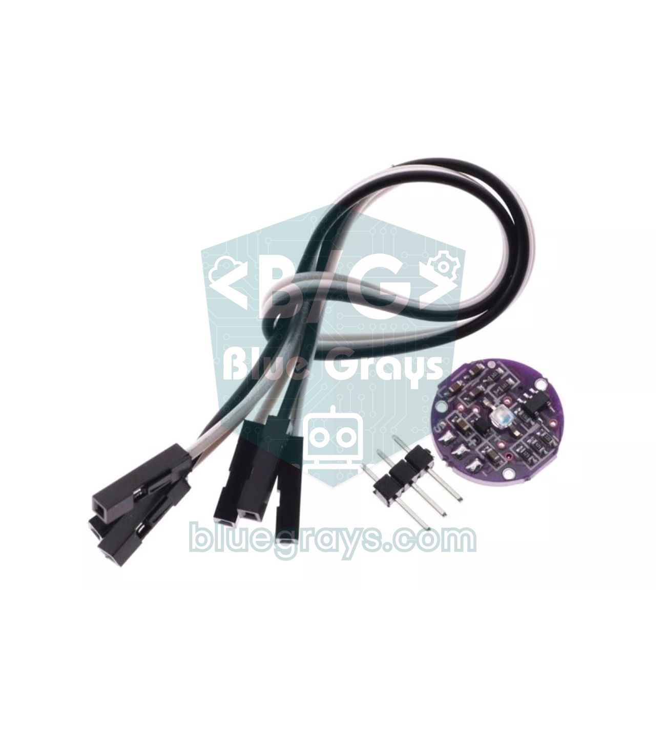
For bridge sensors such as load cells, where both outputs sit at the middle of the supply and the difference between them is only a few millivolts, ready-made chips are more practical: the HX711 contains an amplifier with a gain of up to 128 and a 24-bit ADC. The op-amp on a pulse sensor board, meanwhile, both amplifies and filters the light sensor's weak signal, which is why the Arduino sees a clear pulse wave on the first try.
Op-amp project ideas
- Clap-activated lamp: drive a relay module with the microphone preamp and the ESP32 code with hysteresis.
- VU meter: turn the peak-to-peak amplitude into a bar that rises with the music on a WS2812B LED strip.
- Oven thermometer: measure up to 500 °C with the thermocouple amplifier and show the value on an OLED display.
- Code-free night light: make an LED that turns on in the dark with an LDR and an LM358 comparator, without any microcontroller.
- Digital scale: read a load cell with the HX711 and build a kitchen scale accurate to the gram.
- Motor current monitor: measure your robot car's motor current with a shunt and an op-amp, and stop the motor when the current rises because it has stalled.
Common mistakes and how to fix them
| Symptom | Likely cause | Fix |
|---|---|---|
| Output always at 0 V or at the top | No feedback or connected to the wrong input; gain too high; input outside the input range | Check that Rf goes to the − input, lower the gain, make sure the input is between 0 and V+ − 1.5 V |
| LM741 circuit doesn't work at 5 V | The LM741 needs a symmetric, higher supply | Use an LM358 or MCP6002 |
| Output won't go above 3.5 V | The LM358's output stops at V+ − 1.5 V | Choose the gain accordingly or use a rail-to-rail op-amp |
| Noisy, jittery readings | No supply decoupling, long wires, needlessly high gain | 100 nF on the supply pins, short wires, an RC filter at the output, averaging in software |
| Circuit oscillates on its own | The op-amp drives a long cable or a large capacitive load directly | Add a 100–470 Ω series resistor at the output |
| Comparator output never goes high | The LM393 is open-collector and has no pull-up | Connect 4.7–10 kΩ between the output and the supply |
| ESP32 or Pico pin damaged | The op-amp was powered from 5 V or 12 V and the output exceeded 3.3 V | Power the op-amp from 3.3 V, or add a divider and a clamp diode at the output |
| Output stuck at 0 V with small signals | A negative input offset pins the output low on a single supply | Use a precision op-amp or add a small bias to the input |
An op-amp is a translator that turns the analog world into a language the microcontroller understands: once you know the two rules and the two gain formulas, you can make any signal suitable for the ADC, whether it comes from a microphone, a thermocouple, a shunt resistor or a bridge sensor. Use the Op-amp gain tool to try out values; in the BlueGrays app you'll find analog projects such as light measurement with an LDR, a night light, a digital voltmeter, temperature measurement with an NTC, and flame and gas sensors, step by step with circuit diagrams and code.
Frequently asked questions
What is an op-amp used for?
An op-amp is used to amplify weak signals, compare two voltages, add or subtract signals, filter them and buffer high-impedance sources. In Arduino projects it's mostly used to raise millivolt-level signals from a microphone, a thermocouple or a shunt resistor to a level the ADC can read.
How do you calculate op-amp gain?
For a non-inverting amplifier the gain is 1 + Rf / Rg, and for an inverting amplifier it's −Rf / Rin. For example, with Rf = 100 kΩ and Rg = 1 kΩ the non-inverting gain is 101 and the inverting gain is −100. The value in decibels is 20 × log10(gain).
What is the difference between the LM358 and the LM741?
The LM358 contains two op-amps in one package, runs from a single 3–30 V supply and its input range includes 0 V, so it can be used directly with the Arduino's 5 V. The LM741 is a single op-amp designed for a symmetric supply such as ±15 V and practically doesn't work on a single 5 V supply. Their pinouts are different too.
Can an op-amp run on a single 5 V supply?
Yes, models designed for single-supply use do, such as the LM358, LM324 and MCP6002. For AC signals you have to lift the input to the middle of the supply and take the output limits into account; the LM358's output only reaches about 3.5 V on a 5 V supply.
What is the difference between an op-amp and a comparator?
An op-amp includes frequency compensation so it stays stable with negative feedback, and its output can source and sink current. Comparators such as the LM393 are designed for fast switching without feedback, and most have an open-collector output that needs a pull-up resistor. An op-amp can be used as a slow comparator, but a comparator shouldn't be used as an amplifier.
What is a rail-to-rail op-amp?
A rail-to-rail op-amp's input or output can get within a few tens of millivolts of the supply voltages. For example, the MCP6002 outputs 0.025–4.975 V on a 5 V supply, while the LM358 only reaches about 3.5 V. On 3.3 V boards such as the ESP32 and Raspberry Pi Pico you need a rail-to-rail op-amp to use the full ADC range.
Projects to build after reading this
See all projects
Measuring Light Intensity with an LDR
Want to see how bright your room is as a number? The LDR, a small part that reacts to light, measures the light around it, and the Arduino writes the value to your computer screen every half second. C

Night Light with Ldr
A little night light that turns on by itself when it gets dark and goes off when morning comes. A light sensor measures how bright the room is, and the Arduino switches the LED on when it is dark enou

Reading Light Intensity with the ESP32 LDR Module
Real-time monitoring of the LDR module's raw ADC value and relative light percentage calculated from dark and light reference values in the Serial Monitor. This percentage is not a lux measurement. Teaches the module’s calibration logic. It is ideal to complete this before Project 10, as it is used to determine the threshold value.
Digital Voltmeter with LCD Display
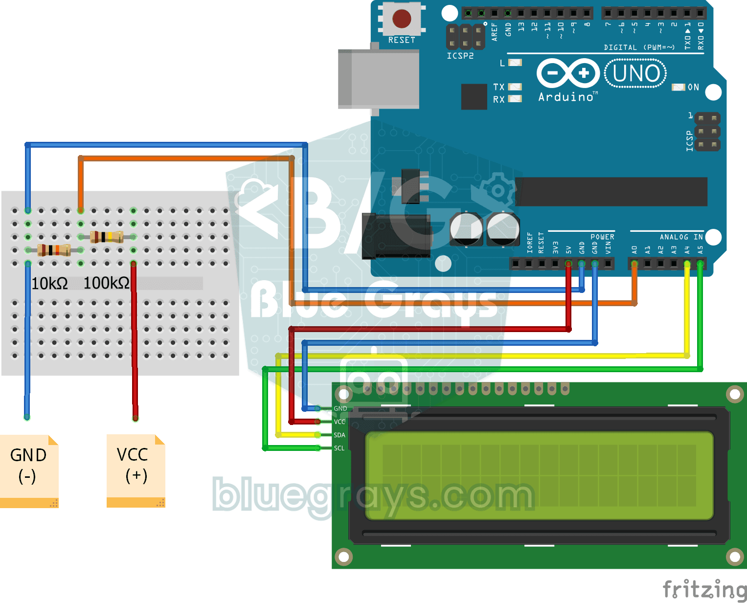
Find out how much voltage a battery or power adapter gives with a meter you built yourself. A divider made of two resistors brings high voltage down to a level the board can read, and the Arduino calc
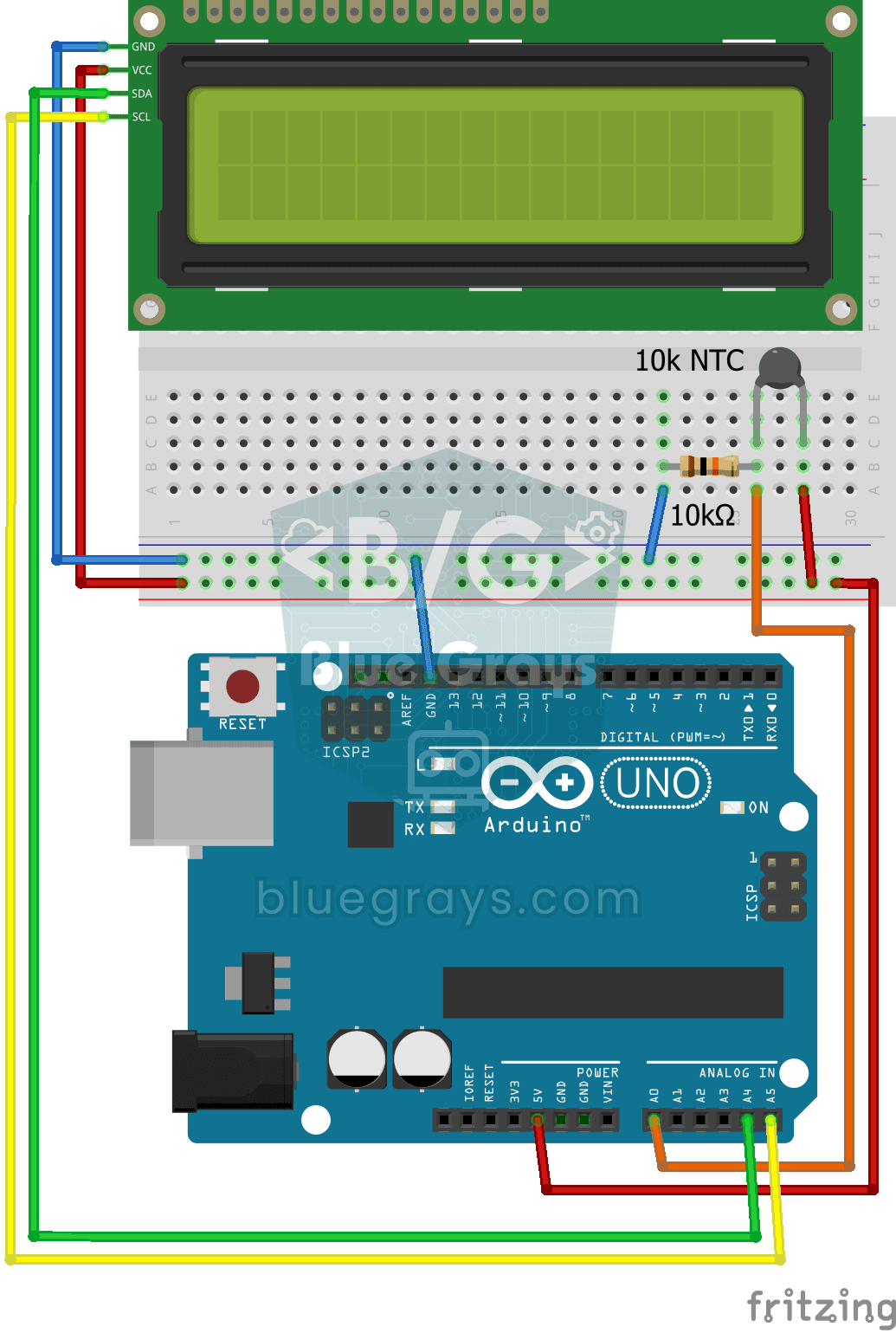
Temperature Measurement with NTC and 2x16 Lcd Display
Measure the temperature around you with a sensor that looks like a tiny bead. This part, called an NTC, lets electricity through more easily as it warms up; the Arduino reads that change, turns it int
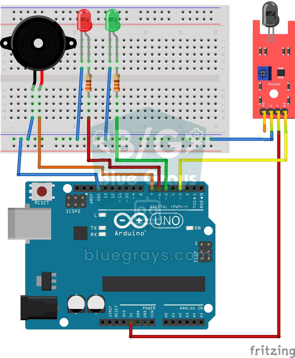
Using a Flame Sensor
A little guard that spots fire before you do, in the kitchen or the workshop. The flame sensor picks up the invisible light that fire gives off; while all is well the green LED is on, and when it sees
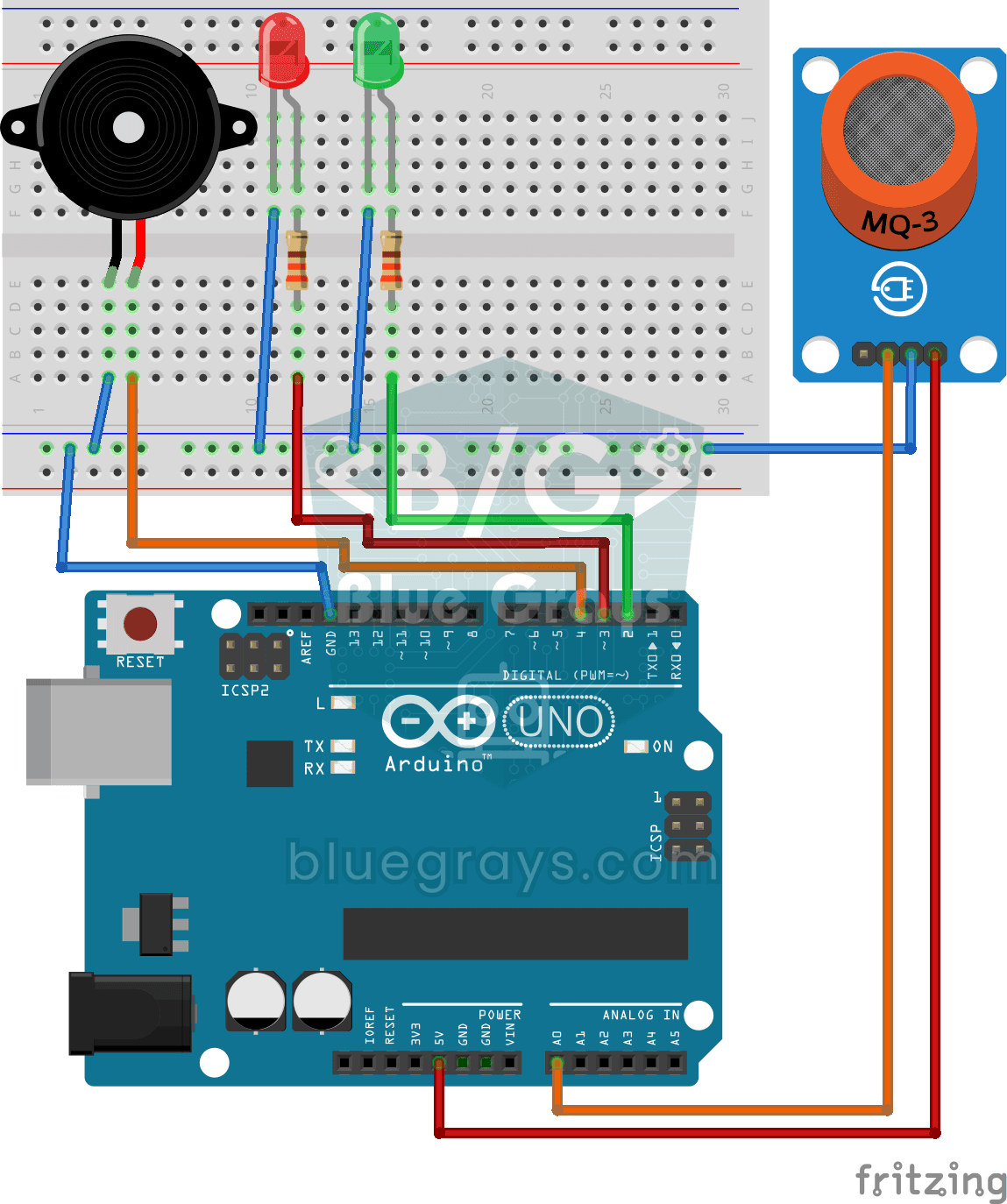
Using a Gas Sensor
A little guard that notices a gas leak in the kitchen before you do. The gas sensor keeps sniffing the air; while everything is fine the green LED stays on, and when the gas in the air passes a certai

ESP32 LED Brightness Control with a Potentiometer (Analog → PWM)
In this project, we control the brightness of an LED analogically using a potentiometer. The ESP32's ADC pin reads the 0-3.3V voltage from the potentiometer, and this value is then converted into a PWM (Pulse Width Modulation) signal and sent to the LED. As a result, as you turn the potentiometer, the LED gradually brightens and dims. With Arduino Core 3.0+, analogWrite() can be used directly; on the ESP32-S2/S3, the ADC resolution is fixed at 12-bit.