
ESP32 Cheap Yellow Display (CYD): Pinout, Setup and LVGL
ESP32 Cheap Yellow Display (ESP32-2432S028R) guide: full pinout, TFT_eSPI and XPT2046 touch setup, calibration, SD card, speaker and a first LVGL UI.

The ESP32 Cheap Yellow Display (CYD for short), sold under the model name ESP32-2432S028R, is a ready-made development board that puts an ESP32, a 2.8-inch color touchscreen, a microSD slot, an RGB LED, a light sensor and a speaker output on a single yellow PCB. The nickname says it all: the board is yellow, it is cheap and it has a display. Plug in one USB cable, upload your sketch and you have a touch interface without soldering anything or wiring a single jumper.
In this guide you will see what is on the board, how to tell the versions apart and the complete pinout. Then you will configure the TFT_eSPI and XPT2046_Touchscreen libraries in the Arduino IDE, print text on the screen, calibrate the touch panel, switch the RGB LED with on-screen buttons, log data to a microSD card and build your first real interface with LVGL. The last sections cover project ideas such as a weather display and a smart home panel, plus fixes for the most common problems.
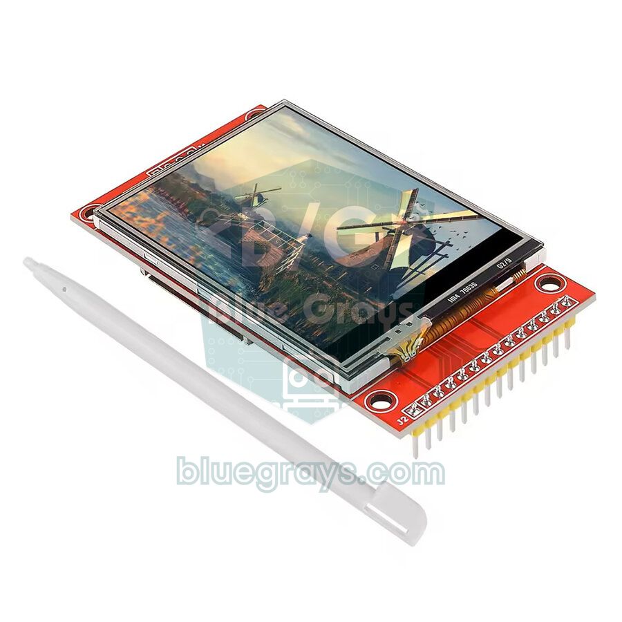
What is the ESP32 Cheap Yellow Display and what is on the board?
At the heart of the board is an ESP32-WROOM-32 module: a dual-core processor running at up to 240 MHz, 520 KB of SRAM, 4 MB of flash, 2.4 GHz Wi-Fi and Bluetooth. Everything you learned in What is the ESP32? applies here too. The display is wired to the ESP32's HSPI bus, while the XPT2046 chip that reads the resistive touch panel sits on the second SPI bus (VSPI) with its own pins. That detail matters, because generic TFT examples assume touch shares the display bus, and they fail on the CYD. There is no PSRAM, so instead of holding the whole frame in memory the image is drawn in chunks.
| Feature | Value |
|---|---|
| Processor module | ESP32-WROOM-32 (dual core, 240 MHz) |
| Memory | 520 KB SRAM, 4 MB flash, no PSRAM |
| Display | 2.8-inch TFT, 240×320 pixels, 16-bit color (RGB565) |
| Display driver | ILI9341 (usually ST7789 on the two-USB version) |
| Touch | Resistive panel, XPT2046 controller |
| Storage | microSD card slot (SPI) |
| Extras | RGB LED, LDR light sensor, speaker output (SC8002B amplifier) |
| USB and power | Micro-USB, CH340 USB-to-serial chip, 5 V |
| Buttons | BOOT (GPIO 0) and RST |
Board versions: what does ESP32-2432S028R mean?
The model name is a summary: 2432 is the resolution (240×320), S028 the screen size (2.8 inches) and the trailing R stands for resistive touch. The same family also includes boards ending in C (capacitive touch) and N (no touch). Because sellers call all of them "Cheap Yellow Display", check the exact model name before you order: the pin mapping and the display driver can change from one version to the next.
| Board | Display | How to spot it | Watch out |
|---|---|---|---|
| ESP32-2432S028R (one USB) | 2.8" 240×320, ILI9341 | Micro-USB port only | The version most examples, and this guide, are based on |
| ESP32-2432S028R (two USB) | 2.8" 240×320, usually ST7789 | Micro-USB and USB-C side by side | Colors may look inverted; needs a driver or invertDisplay change |
| ESP32-2432S024 | 2.4" 240×320 | Smaller screen | Pins and touch chip may differ |
| ESP32-2432S032 | 3.2" 240×320 | Larger board | The capacitive version reads touch over I2C |
| ESP32-3248S035 | 3.5" 320×480, ST7796 | Higher resolution | Needs its own TFT_eSPI setup |
CYD pinout
| Part | Signal and GPIO | Note |
|---|---|---|
| Display (ILI9341) | MOSI 13, MISO 12, SCK 14, CS 15, DC 2 | HSPI bus; RST tied to EN |
| Backlight | GPIO 21 | HIGH = on; can be dimmed with PWM |
| Touch (XPT2046) | CLK 25, MOSI 32, MISO 39, CS 33, IRQ 36 | VSPI bus, separate from the display |
| microSD | SCK 18, MISO 19, MOSI 23, CS 5 | Default VSPI pins |
| RGB LED | Red 4, green 16, blue 17 | Common anode: LOW = on |
| LDR light sensor | GPIO 34 | Input only, read with analogRead |
| Speaker | GPIO 26 | SC8002B amplifier, SPEAK connector |
| BOOT button | GPIO 0 | Can also be read as a button in your sketch |
| Serial port (P1) | TX 1, RX 3 | Shared with the USB-to-serial chip |
| Unused pins | GPIO 22, 27 (CN1), GPIO 35 (P3) | 35 is input only |
The small JST connectors (1.25 mm pitch) along the edge are your door to the outside world. CN1 carries GND, GPIO 22, GPIO 27 and 3.3 V, which is perfect for an I2C sensor: call Wire.begin(27, 22) and plug in a sensor such as the BME280 directly. P3 exposes GPIO 35, 22 and 21, and P1 carries the 5 V input plus the serial TX/RX lines. To check these pins against the ESP32's general restrictions, open the pinout tool.
Arduino IDE setup: board settings and libraries
- Install the ESP32 board package in the Arduino IDE (esp32 by Espressif in the Boards Manager) and select ESP32 Dev Module as the board.
- Connect the board with a USB cable. If no port shows up, install the CH340 driver and make sure your cable carries data, not just power.
- Install TFT_eSPI (Bodmer) and XPT2046_Touchscreen (Paul Stoffregen) from the Library Manager.
- Replace the contents of User_Setup.h in the TFT_eSPI folder with the settings from the next section.
- If the upload stops with "Failed to connect", hold the BOOT button while the upload starts; see ESP32 Failed to connect for details.
TFT_eSPI configuration: User_Setup.h
TFT_eSPI is a very fast library, and it gets that speed from pin settings fixed at compile time. They live in the User_Setup.h file inside the library folder (Documents > Arduino > libraries > TFT_eSPI). Back up the file, delete everything in it and paste the lines below. Updating the library resets this file to its default, so keep your own copy somewhere safe and copy it back after every update.
1// TFT_eSPI/User_Setup.h: CYD (ESP32-2432S028R) ayarı / setup for the CYD
2#define ILI9341_2_DRIVER       // iki USB'li kartta ST7789_DRIVER / two-USB board: ST7789_DRIVER
3#define TFT_WIDTH  240
4#define TFT_HEIGHT 320
5#define TFT_BL   21            // arka ışık / backlight
6#define TFT_BACKLIGHT_ON HIGH
7#define TFT_MISO 12
8#define TFT_MOSI 13
9#define TFT_SCLK 14
10#define TFT_CS   15
11#define TFT_DC    2
12#define TFT_RST  -1            // EN'e bağlı / tied to EN
13#define USE_HSPI_PORT          // ekran HSPI hattında / display on the HSPI bus
14
15#define LOAD_GLCD
16#define LOAD_FONT2
17#define LOAD_FONT4
18#define LOAD_FONT6
19#define LOAD_FONT7
20#define LOAD_FONT8
21#define LOAD_GFXFF
22#define SMOOTH_FONT
23
24#define SPI_FREQUENCY       55000000   // sorun olursa 27000000 / use 27000000 if unstable
25#define SPI_READ_FREQUENCY  20000000
26#define SPI_TOUCH_FREQUENCY  2500000
First test: text on the screen and drawing with touch
1#include <SPI.h>
2#include <TFT_eSPI.h>
3#include <XPT2046_Touchscreen.h>
4
5// Dokunmatik (XPT2046) kendi SPI hattında / touch (XPT2046) on its own SPI bus
6#define XPT2046_IRQ  36
7#define XPT2046_MOSI 32
8#define XPT2046_MISO 39
9#define XPT2046_CLK  25
10#define XPT2046_CS   33
11
12SPIClass touchSpi(VSPI);
13XPT2046_Touchscreen ts(XPT2046_CS, XPT2046_IRQ);
14TFT_eSPI tft;
15
16void setup() {
17  Serial.begin(115200);
18  touchSpi.begin(XPT2046_CLK, XPT2046_MISO, XPT2046_MOSI, XPT2046_CS);
19  ts.begin(touchSpi);
20  ts.setRotation(1);               // ekranla aynı yön / same orientation as the screen
21
22  tft.init();
23  tft.setRotation(1);              // yatay 320x240 / landscape 320x240
24  tft.fillScreen(TFT_BLACK);
25  tft.setTextColor(TFT_WHITE, TFT_BLACK);
26  tft.drawCentreString("BlueGrays CYD", 160, 10, 4);
27  tft.drawCentreString("Ekrana dokun / Touch the screen", 160, 40, 2);
28}
29
30void loop() {
31  if (ts.tirqTouched() && ts.touched()) {
32    TS_Point p = ts.getPoint();
33    // Ham değerleri piksele çevir / convert raw values to pixels
34    int x = map(p.x, 200, 3700, 0, 319);
35    int y = map(p.y, 240, 3800, 0, 239);
36    x = constrain(x, 0, 319);
37    y = constrain(y, 0, 239);
38    tft.fillCircle(x, y, 3, TFT_YELLOW);
39    Serial.printf("ham/raw x=%d y=%d z=%d -> piksel/pixel %d,%d\n", p.x, p.y, p.z, x, y);
40  }
41}
The key line is SPIClass touchSpi(VSPI): it puts the touch controller on the second SPI bus with its own pins, independent of the display. ts.setRotation(1) and tft.setRotation(1) must use the same value; if they differ, the spot you touch and the dot drawn on the screen will not match. In landscape the coordinates run from 0 to 319 for x and 0 to 239 for y. After uploading, try writing on the screen with a stylus; if the lines follow your hand, the display and touch are set up correctly.
Touchscreen calibration (XPT2046)
The XPT2046 does not report pixels but raw values between 0 and 4095. The numbers 200, 3700 and 240, 3800 in the code are the part of that raw range that lines up with the screen edges, and they vary slightly from board to board. To calibrate, open the Serial Monitor at 115200 baud, tap the four corners with a stylus and note the smallest and largest raw x and y values. Put those four numbers into the map() lines and the offset between your touch and the drawn dot drops to a few pixels. The resistive panel also measures pressure: the library's touched() already returns true only for firm enough presses, but if you see jittery values near the edges you can add a higher threshold for p.z.
RGB LED, LDR and speaker: a touch control panel
The RGB LED, LDR and speaker output on the back of the board are enough for your first project. The code below draws three large buttons; tapping a button toggles that LED color and plays a short click on the speaker. The yellow bar at the bottom shows the light sensor reading and refreshes every half second.
1#include <SPI.h>
2#include <TFT_eSPI.h>
3#include <XPT2046_Touchscreen.h>
4
5#define XPT2046_IRQ  36
6#define XPT2046_MOSI 32
7#define XPT2046_MISO 39
8#define XPT2046_CLK  25
9#define XPT2046_CS   33
10
11const int LED_PINS[3] = {4, 16, 17};   // RGB LED: kırmızı, yeşil, mavi (LOW = yanar) / red, green, blue (LOW = on)
12const int LDR_PIN = 34;                // ışık sensörü / light sensor
13const int SPEAKER_PIN = 26;            // hoparlör yükselticisi / speaker amplifier
14const char* NAMES[3] = {"RED", "GREEN", "BLUE"};
15const uint16_t COLORS[3] = {TFT_RED, TFT_GREEN, TFT_BLUE};
16
17SPIClass touchSpi(VSPI);
18XPT2046_Touchscreen ts(XPT2046_CS, XPT2046_IRQ);
19TFT_eSPI tft;
20
21bool ledOn[3] = {false, false, false};
22bool wasTouched = false;
23unsigned long lastLdr = 0;
24
25void drawButton(int i) {
26  int x = 8 + i * 104;                                  // 3 düğme yan yana / 3 buttons side by side
27  tft.fillRoundRect(x, 60, 96, 80, 10, ledOn[i] ? COLORS[i] : TFT_DARKGREY);
28  tft.setTextColor(TFT_WHITE);
29  tft.drawCentreString(NAMES[i], x + 48, 92, 2);
30}
31
32void setup() {
33  for (int i = 0; i < 3; i++) {
34    pinMode(LED_PINS[i], OUTPUT);
35    digitalWrite(LED_PINS[i], HIGH);                    // HIGH = sönük / HIGH = off
36  }
37  touchSpi.begin(XPT2046_CLK, XPT2046_MISO, XPT2046_MOSI, XPT2046_CS);
38  ts.begin(touchSpi);
39  ts.setRotation(1);
40  tft.init();
41  tft.setRotation(1);
42  tft.fillScreen(TFT_BLACK);
43  tft.setTextColor(TFT_WHITE, TFT_BLACK);
44  tft.drawString("BlueGrays panel", 8, 12, 4);
45  for (int i = 0; i < 3; i++) drawButton(i);
46}
47
48void loop() {
49  bool touchedNow = ts.tirqTouched() && ts.touched();
50  if (touchedNow && !wasTouched) {                      // yalnız ilk dokunuşta / only on the first touch
51    TS_Point p = ts.getPoint();
52    int x = map(p.x, 200, 3700, 0, 319);
53    int y = map(p.y, 240, 3800, 0, 239);
54    if (y > 60 && y < 140) {
55      int i = constrain((x - 8) / 104, 0, 2);
56      ledOn[i] = !ledOn[i];
57      digitalWrite(LED_PINS[i], ledOn[i] ? LOW : HIGH);
58      drawButton(i);
59      tone(SPEAKER_PIN, 2000, 30);                      // kısa tık sesi / short click sound
60    }
61  }
62  wasTouched = touchedNow;
63
64  if (millis() - lastLdr > 500) {                       // yarım saniyede bir / every half second
65    lastLdr = millis();
66    int light = analogRead(LDR_PIN);                    // 0-4095
67    tft.fillRect(8, 170, 304, 20, TFT_BLACK);
68    tft.fillRect(8, 170, map(light, 0, 4095, 0, 304), 20, TFT_YELLOW);
69    tft.setTextColor(TFT_WHITE, TFT_BLACK);
70    tft.drawString("LDR: " + String(light) + "    ", 8, 200, 2);
71  }
72}
Because the RGB LED is wired as common anode, the logic is inverted: writing LOW turns a color on and HIGH turns it off, which is why setup() first sets all three pins HIGH. The wasTouched variable stops a button from toggling over and over while your finger stays on the screen; only the moment the touch starts counts. The LDR reading may stay within a narrow range because of the divider resistor on the board, so measure the dark and bright values in your own room and pick the threshold from those. You can plug a small 8 Ω speaker into the speaker connector and play beeps and simple melodies with tone().
Logging data to the microSD card
The card slot uses the ESP32's default VSPI pins (18, 19, 23 and 5 for CS), so SD.begin(5) is all you need. Format the card as FAT32; cards up to 32 GB work without trouble. The example below appends the time and the light level to log.csv every five seconds, and you can open the file later in any spreadsheet program. For general SD card usage, see the SD card module guide.
1#include <SPI.h>
2#include <SD.h>
3
4const int SD_CS = 5;          // microSD: SCK 18, MISO 19, MOSI 23, CS 5
5const int LDR_PIN = 34;
6
7void setup() {
8  Serial.begin(115200);
9  if (!SD.begin(SD_CS)) {     // varsayılan SPI pinleri / default SPI pins
10    Serial.println("SD kart yok / no SD card");
11    return;
12  }
13  Serial.printf("SD: %llu MB\n", SD.cardSize() / (1024 * 1024));
14}
15
16void loop() {
17  File f = SD.open("/log.csv", FILE_APPEND);   // dosyanın sonuna ekle / append to the file
18  if (f) {
19    f.printf("%lu,%d\n", millis() / 1000, analogRead(LDR_PIN));
20    f.close();
21  }
22  delay(5000);
23}Your first interface with LVGL
Drawing buttons, sliders and charts one fillRect at a time gets tiring quickly. LVGL is an open-source graphics library that gives you phone-style widgets (buttons, sliders, lists, charts, tabs) and handles touch input for you. Since version 9 it ships with built-in TFT_eSPI support, so you no longer need to write your own flush function for the display.
- Install the lvgl library (version 9.x) from the Library Manager.
- Copy lv_conf_template.h from the libraries/lvgl folder one level up, next to the lvgl folder, and rename it lv_conf.h.
- Change #if 0 at the top of the file to #if 1 and set LV_USE_TFT_ESPI to 1.
- For larger fonts, also set lines such as LV_FONT_MONTSERRAT_20 to 1; every font takes up flash memory.
1#include <SPI.h>
2#include <lvgl.h>
3#include <TFT_eSPI.h>
4#include <XPT2046_Touchscreen.h>
5
6#define XPT2046_IRQ  36
7#define XPT2046_MOSI 32
8#define XPT2046_MISO 39
9#define XPT2046_CLK  25
10#define XPT2046_CS   33
11#define SCREEN_WIDTH  240
12#define SCREEN_HEIGHT 320
13#define DRAW_BUF_SIZE (SCREEN_WIDTH * SCREEN_HEIGHT / 10 * (LV_COLOR_DEPTH / 8))
14
15SPIClass touchSpi(VSPI);
16XPT2046_Touchscreen ts(XPT2046_CS, XPT2046_IRQ);
17uint32_t drawBuf[DRAW_BUF_SIZE / 4];   // ekranın 1/10'u kadar tampon / buffer for 1/10 of the screen
18lv_obj_t* valueLabel;
19
20// LVGL'e dokunuşu bildir / report touches to LVGL
21void touchRead(lv_indev_t* indev, lv_indev_data_t* data) {
22  if (ts.tirqTouched() && ts.touched()) {
23    TS_Point p = ts.getPoint();
24    data->point.x = map(p.x, 200, 3700, 1, SCREEN_WIDTH);
25    data->point.y = map(p.y, 240, 3800, 1, SCREEN_HEIGHT);
26    data->state = LV_INDEV_STATE_PRESSED;
27  } else {
28    data->state = LV_INDEV_STATE_RELEASED;
29  }
30}
31
32uint32_t tickMs() { return millis(); }   // LVGL'in saat kaynağı / LVGL time source
33
34void onLedButton(lv_event_t* e) {
35  lv_obj_t* btn = lv_event_get_target_obj(e);
36  bool on = lv_obj_has_state(btn, LV_STATE_CHECKED);
37  digitalWrite(4, on ? LOW : HIGH);      // kırmızı LED / red LED
38}
39
40void onSlider(lv_event_t* e) {
41  lv_obj_t* slider = lv_event_get_target_obj(e);
42  lv_label_set_text_fmt(valueLabel, "%d %%", (int)lv_slider_get_value(slider));
43}
44
45void lvglSetup() {
46  pinMode(4, OUTPUT);
47  digitalWrite(4, HIGH);
48  touchSpi.begin(XPT2046_CLK, XPT2046_MISO, XPT2046_MOSI, XPT2046_CS);
49  ts.begin(touchSpi);
50  ts.setRotation(2);
51
52  lv_init();
53  lv_tick_set_cb(tickMs);
54  lv_display_t* disp = lv_tft_espi_create(SCREEN_WIDTH, SCREEN_HEIGHT, drawBuf, sizeof(drawBuf));
55  lv_display_set_rotation(disp, LV_DISPLAY_ROTATION_270);   // yatay kullanım / landscape
56  lv_indev_t* indev = lv_indev_create();
57  lv_indev_set_type(indev, LV_INDEV_TYPE_POINTER);
58  lv_indev_set_read_cb(indev, touchRead);
59
60  lv_obj_t* title = lv_label_create(lv_screen_active());
61  lv_label_set_text(title, "BlueGrays + LVGL");
62  lv_obj_align(title, LV_ALIGN_TOP_MID, 0, 10);
63
64  lv_obj_t* btn = lv_button_create(lv_screen_active());
65  lv_obj_set_size(btn, 120, 50);
66  lv_obj_align(btn, LV_ALIGN_CENTER, 0, -30);
67  lv_obj_add_flag(btn, LV_OBJ_FLAG_CHECKABLE);              // aç-kapa düğmesi / toggle button
68  lv_obj_add_event_cb(btn, onLedButton, LV_EVENT_VALUE_CHANGED, NULL);
69  lv_obj_t* btnLabel = lv_label_create(btn);
70  lv_label_set_text(btnLabel, "LED");
71  lv_obj_center(btnLabel);
72
73  lv_obj_t* slider = lv_slider_create(lv_screen_active());
74  lv_obj_set_width(slider, 220);
75  lv_obj_align(slider, LV_ALIGN_CENTER, 0, 40);
76  lv_obj_add_event_cb(slider, onSlider, LV_EVENT_VALUE_CHANGED, NULL);
77  valueLabel = lv_label_create(lv_screen_active());
78  lv_label_set_text(valueLabel, "0 %");
79  lv_obj_align_to(valueLabel, slider, LV_ALIGN_OUT_BOTTOM_MID, 0, 10);
80}
81
82void lvglLoop() {
83  lv_timer_handler();                    // LVGL çizim ve olayları / LVGL drawing and events
84  delay(5);
85}
Add setup() and loop() at the end of this code: call only lvglSetup() in setup() and only lvglLoop() in loop(). The screen is drawn in chunks through a buffer one tenth of the screen size (about 15 KB), which is a good balance for a CYD without PSRAM. Because LVGL handles the rotation itself, touch coordinates are passed in portrait order (240×320) and LVGL maps them to the landscape screen. The button is checkable, so every tap toggles the red LED, and the slider writes its percentage to the label below it.
CYD project ideas: weather station and smart home panel
- Weather display: Use the ESP32 weather API guide to show temperature, humidity and the daily forecast with icons.
- Smart home panel: Control lights and plugs with on-screen buttons via MQTT and Home Assistant.
- Desk clock: Show internet time from NTP in large digits and dim the backlight at night based on the LDR.
- Sensor dashboard: Plot temperature, humidity and pressure from an I2C sensor on CN1 as a live chart.
- Data logger: Save readings to the microSD card and show a chart of the last 24 hours.
- Touch games: Build tic-tac-toe, snake or memory games you play with the stylus.
Common problems and fixes
| Symptom | Likely cause | Fix |
|---|---|---|
| Screen stays white or black | User_Setup.h not configured or wrong driver | Copy the settings from this guide; try ST7789 on a two-USB board |
| Colors look like a negative | Driver or color inversion setting does not match | Add tft.invertDisplay(1) or switch the driver |
| Touch does not respond | Touch assumed to share the display SPI bus | Use touchSpi(VSPI) with pins 25, 32, 39, 33 |
| Touch point and drawing are offset | Calibration values do not fit the board | Measure the raw corner values and update the map() lines |
| Flicker or garbled lines | SPI clock too high | Lower SPI_FREQUENCY to 27000000 |
| Resets when Wi-Fi starts | USB port or cable cannot supply enough current | Use a short, good cable and an adapter rated at least 1 A |
| Upload does not start | No CH340 driver or board not in download mode | Install the driver and press BOOT as the upload starts |
The ESP32 Cheap Yellow Display is the shortest path to an ESP32 project with a screen: no tangle of wires, no soldering, just code. If you prefer working with separate modules, the ILI9341 TFT display guide covers the same driver on a breadboard. In the BlueGrays app you will find the weather, NTP clock, web server and LDR projects with step-by-step circuit diagrams and code, ready to move onto the CYD's screen.
Frequently asked questions
Which board do I select for the Cheap Yellow Display in Arduino IDE?
Select ESP32 Dev Module, because the CYD carries a standard ESP32-WROOM-32 module. Leave the flash size at 4 MB and drop the upload speed to 115200 if uploads fail. If no port appears, install the CH340 driver.
Why is my CYD screen white?
A white screen means the backlight is on but the display driver is not receiving valid data. Almost always the TFT_eSPI User_Setup.h file is not configured for the CYD or the wrong driver is selected. Check the pin settings, and on boards with two USB ports try the ST7789 driver instead of ILI9341.
Which GPIO pins can I use on the ESP32 Cheap Yellow Display?
The usable pins are GPIO 22 and 27 on the CN1 connector and GPIO 35 on P3; GPIO 35 is input only. For I2C sensors call Wire.begin(27, 22) and power the sensor from the 3.3 V and GND pins on CN1. Leave GPIO 21 alone, since it drives the backlight.
Does LVGL run on the CYD without PSRAM?
Yes, LVGL 9 runs smoothly on the CYD. Since there is no PSRAM, you use a draw buffer one tenth of the screen (about 15 KB) instead of a full frame. If you add many large fonts or images, flash and RAM become the real limit, so disable fonts you do not use in lv_conf.h.
Can I use the touchscreen and the SD card at the same time?
Yes, but it needs extra setup, because both use the ESP32's VSPI peripheral on different pins. The easiest way is a touch library that uses software SPI. The other option is to restart the SPI bus with the SD pins before each card access and with the touch pins afterwards.
Can the Cheap Yellow Display run on a battery?
The board runs on 5 V and usually draws 100–250 mA with the backlight and Wi-Fi on. For battery power use a Li-ion cell with a TP4056 charger and a 5 V boost converter, or simply a power bank. To extend battery life, turn off the screen and Wi-Fi when idle and put the ESP32 to sleep.
Projects to build after reading this
See all projects
Reading Light Intensity with the ESP32 LDR Module
Real-time monitoring of the LDR module's raw ADC value and relative light percentage calculated from dark and light reference values in the Serial Monitor. This percentage is not a lux measurement. Teaches the module’s calibration logic. It is ideal to complete this before Project 10, as it is used to determine the threshold value.

ESP32 HTTPClient + Weather API (with SSD1306 OLED Display)
In this project the ESP32 makes a REST API call over the internet to a weather API (wttr.in) using HTTPClient.h. Unlike the I2C LCD version, it uses an SSD1306 OLED (128×64) display, with large text and vector icons for a richer look. Seven weather icons (sunny, rainy, snowy and more) are drawn on the fly, with no bitmap files.

ESP32 HTTPClient + Weather API (with LCD Screen)
In this project the ESP32 makes a REST API call over the internet to a weather API (wttr.in) using HTTPClient.h. The JSON response is parsed with ArduinoJson v7, and the city, temperature, humidity, weather and wind are shown on an I2C LCD. wttr.in needs no API key; just type the name of any city.

Real-Time Clock from the Internet via ESP32 NTP
The ESP32 connects to Wi-Fi and fetches the real time from NTP (Network Time Protocol) servers with millisecond precision. configTzTime() applies the Turkey time zone (TRT, UTC+3) automatically, and in countries with daylight saving time the DST switch is handled by a POSIX TZ string. The time is printed both to the Serial Monitor and to an optional I2C LCD.

ESP32 Asynchronous Web Server (with IP Display on LCD)
In this project, we’re turning the ESP32 into an asynchronous web server that you can control from your phone or computer on the same Wi-Fi network. Thanks to the ESPAsyncWebServer library, the server can process multiple requests simultaneously (unlike the classic WebServer.h, which blocks on a single request). You’ll be able to open the ESP32’s IP address in a browser and click the ON/OFF buttons (the /on and /off routes) to turn the LED connected to GPIO 5 on and off.
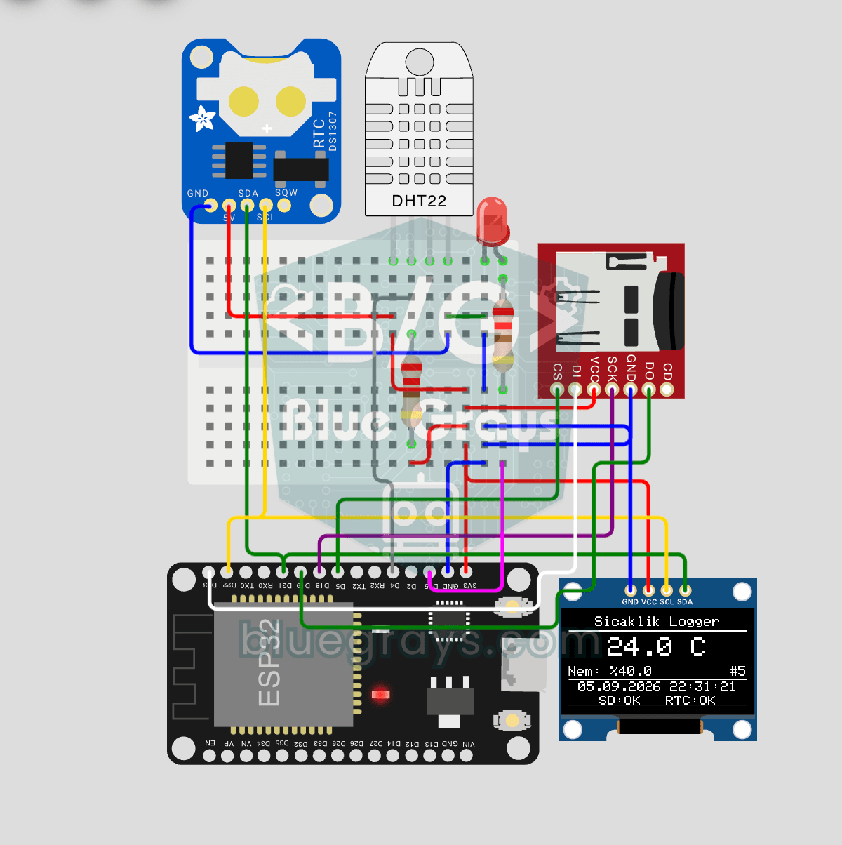
ESP32 Temperature Data Logger (DHT22 + DS1307 RTC + microSD + OLED)
Build a timed temperature and humidity logger with the ESP32! A DHT22 sensor reads temperature and humidity once a minute, and each reading is saved to a microSD card in CSV format with a real-time stamp from the DS1307 RTC module. The OLED display shows the latest temperature, humidity, timestamp and total number of records live, in large text.

ESP32 RGB LED Control
Unlimited color generation with a single RGB LED instead of 3 separate LEDs. As in Arduino, we make a rainbow transition by setting the R/G/B values with analogWrite(). Color theory (such as red+green=yellow) is seen practically.

ESP32 Melody Playback with Buzzer
Playing a simple melody (Twinkle Twinkle Little Star) with a passive buzzer. We play notes with tone() and noTone() functions like in Arduino - ESP32 works with the same syntax as Arduino Core 3.0+. Passive buzzer must be used (active buzzer does not play melody).