
NPK Sensor Arduino: Read Nitrogen, Phosphorus, Potassium (RS485)
NPK sensor with Arduino: MAX485 wiring and 12 V power, the Modbus request frame, an N-P-K value table, calibration limits and ESP32 field monitoring code.

An NPK sensor with Arduino lets you monitor the nitrogen (N), phosphorus (P) and potassium (K) in your soil in mg/kg; it is an industrial soil probe that talks over an RS485 line using Modbus RTU. To connect it to an Arduino you add a MAX485 transceiver, power the sensor from 12 V and send an 8-byte request frame; within a few milliseconds the sensor answers with all three values. It is one of the most searched-for sensors for tracking fertilizer needs in greenhouses, gardens and small fields.
In this guide you will see step by step how to wire the sensor to a MAX485 module and an Arduino, what every byte of the Modbus frame means, how the CRC is calculated, how to turn the reply into numbers and how to monitor a field over Wi-Fi with an ESP32. We will also cover something most sellers leave out: the measurement limits of low-cost NPK sensors and how you should calibrate their readings.
What is an NPK soil sensor and how does it work?
Most NPK sensors on the market (the JXBS-3001-NPK-RS and its clones) are probes with three stainless steel pins, an IP68 rating and an epoxy body. Once the pins are fully buried, the sensor measures the electrical properties of the soil solution and converts them into nitrogen, phosphorus and potassium estimates with formulas in its firmware. There is no analog output: the values are only sent digitally over RS485, and only when asked. That is why you use the Arduino's serial port rather than its analog pins. You will see in detail in the calibration section why this sensor is not a lab instrument.
| Feature | Typical value |
|---|---|
| Measured values | Nitrogen (N), phosphorus (P), potassium (K) |
| Range | 0–1999 mg/kg (mg/kg = ppm) |
| Resolution | 1 mg/kg |
| Stated accuracy | ±2% FS (only under the maker's own calibration conditions) |
| Supply | 5–30 V or 9–24 V DC depending on the model; 12 V suits both |
| Interface | RS485, Modbus RTU, 9600 baud, 8N1 (4800 on some models) |
| Default address | 0x01 |
| Response time | Under 1 second |
| Body and pins | IP68, 316 stainless steel |
Why do you need RS485 and a MAX485?
RS485 is a communication standard that carries data as the voltage difference between two wires (A and B). This makes it very resistant to noise, and it works even with cables longer than 100 meters out in a field; up to 32 devices can share one line. The Arduino's serial port, by contrast, speaks TTL levels (0 and 5 V). The MAX485 module translates between the two: it turns data from the Arduino's TX pin into the A/B difference, and the A/B difference coming from the sensor into a signal the RX pin understands. RS485 is half duplex, meaning a device either talks or listens at any moment; the module's DE and RE pins select the direction. The serial basics are in the UART serial communication guide.
NPK sensor wiring: wire colors and the MAX485
| Sensor wire | Function | Connects to |
|---|---|---|
| Brown | Power + | + of the 12 V supply |
| Black | Power - | - of the 12 V supply and Arduino GND (common) |
| Yellow | RS485 A (+) | MAX485 A |
| Blue | RS485 B (-) | MAX485 B |
| MAX485 pin | Arduino Uno | ESP32 (MAX3485) | Raspberry Pi Pico (MAX3485) |
|---|---|---|---|
| VCC | 5V | 3V3 | 3V3(OUT) |
| GND | GND | GND | GND |
| RO (receiver output) | D2 | GPIO 16 (RX2) | GP1 (UART0 RX) |
| DI (driver input) | D3 | GPIO 17 (TX2) | GP0 (UART0 TX) |
| DE and RE (tied) | D7 | GPIO 4 | GP2 |
| A and B | Sensor's yellow and blue wires | Same | Same |
Power the sensor from a 12 V adapter. The Arduino can run from USB or from the same adapter stepped down to 5 V with an LM2596 buck converter. Either way, the adapter's negative lead must be joined to the Arduino's GND: even though RS485 is differential, the voltage range the receiver accepts is limited relative to the common ground. Cables of a few meters need no termination resistor; on lines longer than 50 meters, a 120 Ω resistor at both ends prevents reflections. Many MAX485 modules already have one fitted. On long runs, use twisted-pair cable such as Cat5 for A and B.
The Modbus request frame: what do we send to the sensor?
In Modbus RTU the master (the Arduino) always starts the conversation; the sensor answers only when it is asked. To read values you use function 03 (Read Holding Registers). On JXBS-type NPK sensors, nitrogen is in register 0x001E, phosphorus in 0x001F and potassium in 0x0020; because they are consecutive, all three can be read with a single request. This 8-byte frame asks exactly that: 01 03 00 1E 00 03 65 CD.
| Byte | Value (hex) | Meaning |
|---|---|---|
| 1 | 01 | Sensor address |
| 2 | 03 | Function: read registers |
| 3–4 | 00 1E | Start register (nitrogen) |
| 5–6 | 00 03 | Number of registers to read (N, P, K) |
| 7–8 | 65 CD | CRC16 checksum, low byte first |
The sensor's reply is 11 bytes: address (01), function (03), data byte count (06), three values of two bytes each and a two-byte CRC. For example, in the reply 01 03 06 00 20 00 0F 00 6E 11 5D, nitrogen is 0x0020 = 32 mg/kg, phosphorus 0x000F = 15 mg/kg and potassium 0x006E = 110 mg/kg. In each value the high byte comes first: value = high byte × 256 + low byte. The CRC is the other way around, low byte first; this small detail is the most common mix-up in Modbus.
| Register | Value | Unit | Frame to read it alone |
|---|---|---|---|
| 0x001E | Nitrogen (N) | mg/kg | 01 03 00 1E 00 01 E4 0C |
| 0x001F | Phosphorus (P) | mg/kg | 01 03 00 1F 00 01 B5 CC |
| 0x0020 | Potassium (K) | mg/kg | 01 03 00 20 00 01 85 C0 |
| 0x001E–0x0020 | N, P and K together | mg/kg | 01 03 00 1E 00 03 65 CD |
Arduino Uno code: reading N, P and K
The code needs no extra library; it uses SoftwareSerial, which comes with the Arduino IDE. It calculates the CRC for every request, checks the reply's address, function, length and CRC, and prints valid values to the Serial Monitor. Open the Serial Monitor at 9600 baud; with correct wiring you will see N, P and K every two seconds.
1// NPK toprak sensörü (RS485 Modbus RTU) + MAX485 + Arduino Uno
2// NPK soil sensor (RS485 Modbus RTU) + MAX485 + Arduino Uno
3#include <SoftwareSerial.h>
4
5const uint8_t PIN_RO    = 2;     // MAX485 RO -> Arduino RX
6const uint8_t PIN_DI    = 3;     // MAX485 DI <- Arduino TX
7const uint8_t PIN_DE_RE = 7;     // DE ve RE birleşik / DE and RE tied together
8
9const uint8_t  SENSOR_ADDR = 0x01;     // varsayılan adres / default address
10const uint16_t REG_N       = 0x001E;   // azot; fosfor 0x001F, potasyum 0x0020 / nitrogen; P 0x001F, K 0x0020
11
12SoftwareSerial rs485(PIN_RO, PIN_DI);
13
14// Modbus CRC16 (polinom 0xA001) / Modbus CRC16 (polynomial 0xA001)
15uint16_t crc16(const uint8_t *buf, uint8_t len) {
16  uint16_t crc = 0xFFFF;
17  for (uint8_t i = 0; i < len; i++) {
18    crc ^= buf[i];
19    for (uint8_t b = 0; b < 8; b++) {
20      if (crc & 1) crc = (crc >> 1) ^ 0xA001;
21      else crc >>= 1;
22    }
23  }
24  return crc;
25}
26
27// 03 fonksiyonuyla ardışık yazmaçları oku (en çok 8) / read up to 8 consecutive registers with function 03
28bool readRegisters(uint16_t start, uint8_t count, uint16_t *out) {
29  uint8_t req[8] = { SENSOR_ADDR, 0x03, (uint8_t)(start >> 8), (uint8_t)(start & 0xFF), 0x00, count, 0, 0 };
30  uint16_t crc = crc16(req, 6);
31  req[6] = crc & 0xFF;               // CRC: önce düşük bayt / low byte first
32  req[7] = crc >> 8;
33
34  while (rs485.available()) rs485.read();   // eski baytları at / drop old bytes
35  digitalWrite(PIN_DE_RE, HIGH);            // gönderme modu / transmit mode
36  rs485.write(req, 8);
37  digitalWrite(PIN_DE_RE, LOW);             // alma modu / receive mode
38
39  uint8_t resp[21];
40  uint8_t need = 5 + 2 * count;             // adres + fonksiyon + bayt sayısı + veri + CRC / addr + func + count + data + CRC
41  uint8_t got = 0;
42  unsigned long t0 = millis();
43  while (got < need && millis() - t0 < 500) {        // 500 ms zaman aşımı / 500 ms timeout
44    if (rs485.available()) resp[got++] = rs485.read();
45  }
46  if (got < need || resp[0] != SENSOR_ADDR || resp[1] != 0x03 || resp[2] != 2 * count) return false;
47  uint16_t rxCrc = resp[need - 2] | ((uint16_t)resp[need - 1] << 8);
48  if (crc16(resp, need - 2) != rxCrc) return false;  // bozuk yanıt / corrupted reply
49  for (uint8_t i = 0; i < count; i++) out[i] = ((uint16_t)resp[3 + 2 * i] << 8) | resp[4 + 2 * i];
50  return true;
51}
52
53void setup() {
54  Serial.begin(9600);
55  rs485.begin(9600);                 // sensörün varsayılan hızı / sensor default baud rate
56  pinMode(PIN_DE_RE, OUTPUT);
57  digitalWrite(PIN_DE_RE, LOW);
58  Serial.println(F("NPK sensoru hazir / NPK sensor ready"));
59}
60
61void loop() {
62  uint16_t npk[3];
63  if (readRegisters(REG_N, 3, npk)) {
64    Serial.print(F("N: "));  Serial.print(npk[0]);
65    Serial.print(F("  P: ")); Serial.print(npk[1]);
66    Serial.print(F("  K: ")); Serial.print(npk[2]);
67    Serial.println(F("  mg/kg"));
68  } else {
69    Serial.println(F("Yanit yok ya da CRC hatasi / no reply or CRC error"));
70  }
71  delay(2000);
72}| Part | What it does |
|---|---|
| crc16() | Calculates the Modbus CRC16 with polynomial 0xA001 |
| DE/RE HIGH, then LOW | Puts the MAX485 in transmit mode, then back to listening once the frame is out |
| need = 5 + 2 × count | Expected reply length: 3 header bytes, the data and 2 CRC bytes |
| 500 ms timeout | The program does not hang if the sensor stays silent |
| CRC and address check | Discards replies corrupted by noise or coming from another device |
Interpreting the readings: NPK value table
The sensor gives you a number in mg/kg, but whether that number is good or bad for your plants depends on the soil type, the crop and the lab method used. The ranges below are rough limits that often appear in agronomy guides and are only a starting point. Do not decide how much fertilizer to apply by comparing an uncalibrated sensor to this table; use it to see which zone your calibrated readings fall into.
| Nutrient | Low | Medium | High | Note |
|---|---|---|---|---|
| Nitrogen (nitrate-N) | Below 10 mg/kg | 10–25 mg/kg | Above 25 mg/kg | 25 mg/kg is a widely used threshold for corn; changes quickly with irrigation and rain |
| Phosphorus (Olsen P) | Below 10 mg/kg | 10–20 mg/kg | Above 20 mg/kg | Moves slowly in soil and changes over months |
| Potassium (exchangeable K) | Below 100 mg/kg | 100–200 mg/kg | Above 200 mg/kg | Higher values are normal in clay soils |
Calibration limits: does this sensor really measure NPK?
To be honest, low-cost RS485 NPK sensors do not measure nitrogen, phosphorus and potassium separately by chemistry. They contain no ion-selective element; what they really measure is the conductivity (EC) of the soil solution, which they split into three numbers with fixed coefficients. That is why the three values usually rise and fall together, go up as the soil gets wet, and show high NPK even when the sensor is dipped in salt water. This does not make the sensor useless: readings taken in the same field, at the same moisture and depth, reliably show the change after fertilizing and the trend over time. But as absolute values they are no substitute for a lab soil test.
- Take soil samples from 3–5 different spots in the field and have a lab test them for N, P and K.
- Measure the same spots with the sensor at the same moisture (for example, one day after irrigation), with the pins fully buried 10–20 cm (4–8 in) deep.
- Take 3 readings at each spot and use the average; a single reading can mislead you because of a stone or an air gap.
- Fit a two-point line between the lab results and the sensor averages and add it to the code as a correction.
- Redo the calibration when the soil type or fertilizer changes; one check at the start of each season is enough.
1// İki noktalı düzeltme: laboratuvar sonucuyla sensör okumasını eşleştir
2// Two-point correction: match sensor readings to lab results
3float calibrate(uint16_t raw, float rawLow, float labLow, float rawHigh, float labHigh) {
4  return labLow + (raw - rawLow) * (labHigh - labLow) / (rawHigh - rawLow);
5}
6
7// Örnek: sensör 40 iken laboratuvar 18, sensör 120 iken 52 mg/kg dedi
8// Example: sensor 40 -> lab 18, sensor 120 -> lab 52 mg/kg (loop() içinde / inside loop())
9float nitrogen = calibrate(npk[0], 40, 18, 120, 52);Field monitoring with an ESP32
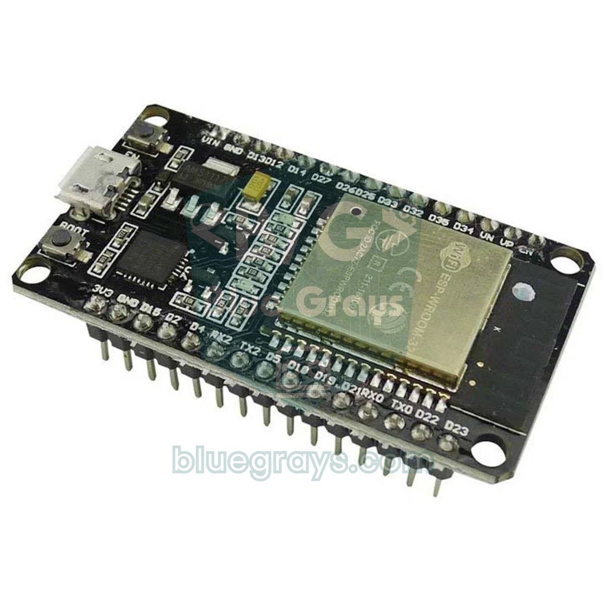
With an ESP32 you can watch the readings on your phone over Wi-Fi. Because the ESP32 runs on 3.3 V, use a MAX3485 or an auto-direction RS485 module that handles the direction pin itself, instead of the 5 V MAX485. If all you have is a MAX485, power it from 5 V and bring its RO output down to 3.3 V with a voltage divider. The code below takes a reading every minute and shows the latest values on a web page and at /json; that JSON is easy to feed into a spreadsheet or a home automation system.
1// ESP32 + RS485 NPK sensörü: Wi-Fi ile tarla izleme / ESP32 + RS485 NPK sensor: field monitoring over Wi-Fi
2#include <WiFi.h>
3#include <WebServer.h>
4
5const char* WIFI_SSID = "AgAdi";          // Wi-Fi adın / your Wi-Fi name
6const char* WIFI_PASS = "Sifre123";       // Wi-Fi şifren / your Wi-Fi password
7
8const int PIN_RX    = 16;                 // MAX3485 RO
9const int PIN_TX    = 17;                 // MAX3485 DI
10const int PIN_DE_RE = 4;                  // DE + RE
11const uint8_t  SENSOR_ADDR = 0x01;
12const uint16_t REG_N = 0x001E;
13const unsigned long READ_EVERY_MS = 60000;   // dakikada bir ölç / measure once a minute
14
15HardwareSerial rs485(2);                  // UART2
16WebServer server(80);
17
18uint16_t lastN = 0, lastP = 0, lastK = 0;
19bool lastOk = false;
20uint32_t readCount = 0;
21unsigned long lastRead = 0;
22
23uint16_t crc16(const uint8_t *buf, uint8_t len) {
24  uint16_t crc = 0xFFFF;
25  for (uint8_t i = 0; i < len; i++) {
26    crc ^= buf[i];
27    for (uint8_t b = 0; b < 8; b++) crc = (crc & 1) ? (crc >> 1) ^ 0xA001 : crc >> 1;
28  }
29  return crc;
30}
31
32bool readRegisters(uint16_t start, uint8_t count, uint16_t *out) {
33  uint8_t req[8] = { SENSOR_ADDR, 0x03, (uint8_t)(start >> 8), (uint8_t)(start & 0xFF), 0x00, count, 0, 0 };
34  uint16_t crc = crc16(req, 6);
35  req[6] = crc & 0xFF;
36  req[7] = crc >> 8;
37  while (rs485.available()) rs485.read();
38  digitalWrite(PIN_DE_RE, HIGH);
39  rs485.write(req, 8);
40  rs485.flush();                          // son bayt çıkana kadar bekle / wait until the last byte is out
41  digitalWrite(PIN_DE_RE, LOW);
42
43  uint8_t resp[21];
44  uint8_t need = 5 + 2 * count, got = 0;
45  unsigned long t0 = millis();
46  while (got < need && millis() - t0 < 500) {
47    if (rs485.available()) resp[got++] = rs485.read();
48  }
49  if (got < need || resp[0] != SENSOR_ADDR || resp[1] != 0x03 || resp[2] != 2 * count) return false;
50  if (crc16(resp, need - 2) != (resp[need - 2] | (resp[need - 1] << 8))) return false;
51  for (uint8_t i = 0; i < count; i++) out[i] = (resp[3 + 2 * i] << 8) | resp[4 + 2 * i];
52  return true;
53}
54
55void handleRoot() {
56  String html = "<!DOCTYPE html><html><head><meta name='viewport' content='width=device-width'>";
57  html += "<meta http-equiv='refresh' content='30'></head><body><h2>NPK (mg/kg)</h2>";
58  html += "<p>N: " + String(lastN) + "<br>P: " + String(lastP) + "<br>K: " + String(lastK) + "</p>";
59  html += "<p>" + String(lastOk ? "Sensor OK" : "Sensor yanit vermiyor / no reply");
60  html += " - olcum / readings: " + String(readCount) + "</p></body></html>";
61  server.send(200, "text/html", html);
62}
63
64void handleJson() {                       // başka sistemler için / for other systems
65  String json = "{\"n\":" + String(lastN) + ",\"p\":" + String(lastP) + ",\"k\":" + String(lastK);
66  json += ",\"ok\":" + String(lastOk ? "true" : "false") + "}";
67  server.send(200, "application/json", json);
68}
69
70void setup() {
71  Serial.begin(115200);
72  rs485.begin(9600, SERIAL_8N1, PIN_RX, PIN_TX);
73  pinMode(PIN_DE_RE, OUTPUT);
74  digitalWrite(PIN_DE_RE, LOW);
75  WiFi.mode(WIFI_STA);
76  WiFi.begin(WIFI_SSID, WIFI_PASS);
77  unsigned long t0 = millis();
78  while (WiFi.status() != WL_CONNECTED && millis() - t0 < 15000) delay(250);
79  Serial.println(WiFi.status() == WL_CONNECTED ? WiFi.localIP().toString() : String("Wi-Fi yok / no Wi-Fi"));
80  server.on("/", handleRoot);
81  server.on("/json", handleJson);
82  server.begin();
83  lastRead = millis() - READ_EVERY_MS;    // ilk ölçüm hemen / first reading at once
84}
85
86void loop() {
87  server.handleClient();
88  if (millis() - lastRead >= READ_EVERY_MS) {
89    lastRead = millis();
90    uint16_t v[3];
91    lastOk = readRegisters(REG_N, 3, v);
92    if (lastOk) {
93      lastN = v[0]; lastP = v[1]; lastK = v[2];
94      readCount++;
95      Serial.printf("N=%u P=%u K=%u mg/kg\n", lastN, lastP, lastK);
96    } else {
97      Serial.println("Yanit yok / no reply");
98    }
99  }
100}
If there is no power in the field, you will need a battery and a small solar panel. Since the sensor draws current even when it is not measuring, switch the 12 V line on with a MOSFET or relay only during a reading, and put the ESP32 into deep sleep between readings. That way, a station measuring every 30 minutes runs for days on a small lithium battery. After powering the sensor, wait a few seconds before measuring. For remote fields out of Wi-Fi range, a LoRa module gives you kilometers of range, and you can estimate battery life with the battery life calculator.
MicroPython code for the Raspberry Pi Pico
On the Pico the same frame is sent over the UART. In MicroPython a UART write drops the data into a buffer and returns immediately, so the code waits for the time the frame needs to leave the line (about 8.3 ms for 8 bytes at 9600 baud) before switching the direction pin to receive. Power the MAX3485 module from the Pico's 3V3(OUT) pin.
1# Raspberry Pi Pico + MAX3485 + NPK sensörü (MicroPython)
2# Raspberry Pi Pico + MAX3485 + NPK sensor (MicroPython)
3from machine import UART, Pin
4import time
5
6BAUD = 9600
7uart = UART(0, baudrate=BAUD, tx=Pin(0), rx=Pin(1))
8de_re = Pin(2, Pin.OUT, value=0)      # 1 = gönder / transmit, 0 = dinle / receive
9
10def crc16(data):
11    crc = 0xFFFF
12    for b in data:
13        crc ^= b
14        for _ in range(8):
15            crc = (crc >> 1) ^ 0xA001 if crc & 1 else crc >> 1
16    return crc
17
18def read_registers(addr, start, count):
19    req = bytes([addr, 0x03, start >> 8, start & 0xFF, 0x00, count])
20    c = crc16(req)
21    req += bytes([c & 0xFF, c >> 8])
22    while uart.any():
23        uart.read()                     # eski baytları at / drop old bytes
24    de_re.value(1)
25    uart.write(req)
26    time.sleep_us(len(req) * 10 * 1000000 // BAUD + 500)   # çerçeve hatta çıksın / let the frame leave
27    de_re.value(0)
28    need = 5 + 2 * count
29    resp = b""
30    t0 = time.ticks_ms()
31    while len(resp) < need and time.ticks_diff(time.ticks_ms(), t0) < 500:
32        if uart.any():
33            resp += uart.read(need - len(resp))
34    if len(resp) < need or resp[0] != addr or resp[1] != 0x03:
35        return None
36    if crc16(resp[:-2]) != resp[-2] | (resp[-1] << 8):
37        return None                     # CRC hatası / CRC error
38    return [resp[3 + 2 * i] << 8 | resp[4 + 2 * i] for i in range(count)]
39
40while True:
41    v = read_registers(0x01, 0x001E, 3)
42    if v:
43        print("N:", v[0], "P:", v[1], "K:", v[2], "mg/kg")
44    else:
45        print("Yanit yok / no reply")
46    time.sleep(2)
Common mistakes and fixes
- No reply at all: A and B are swapped, the sensor is not getting 12 V, the grounds are not common or the baud rate is wrong; swap A and B first, then try 4800 baud.
- Always reads 0: the pins are in the air or in bone-dry soil; bury the sensor fully in moist soil with no air gaps between the pins.
- CRC error: the cable is long and noisy, or DE/RE switches too early; use twisted pair and make sure flush() is called on the ESP32.
- Values of 65535 or absurdly large: you are reading the wrong register; check the register map in your sensor's manual.
- Values jump after irrigation: this is normal, because the sensor responds to conductivity; always take readings at similar moisture.
- The program freezes while reading: the read loop has no timeout; add a 500 ms timeout as in the code.
NPK sensor project ideas
- Smart greenhouse: track NPK, moisture and temperature on a single dashboard; details in the smart greenhouse project.
- Fertilizer log: record the NPK change after each feeding in a spreadsheet; the ESP32 with Google Sheets method comes in handy.
- Irrigation water check: compare soil readings with the conductivity of your irrigation water using a TDS sensor.
- Automatic watering: water with a mini water pump when moisture drops, and time fertilizing by the NPK trend.
- School garden station: compare values from different plots and turn it into a science fair project.
The NPK sensor is also a great way to learn industrial RS485 communication and the Modbus protocol; the frame and CRC logic you learned here is the same on hundreds of devices, from energy meters to weather stations. Do not trust the numbers blindly: calibrate and follow the trends. In the BlueGrays app, the Smart Irrigation Station project shows you step by step how to build a circuit with a moisture sensor and a pump, which you can extend with the NPK sensor.
Frequently asked questions
How do I connect an NPK sensor to Arduino?
The sensor has an RS485 output, so you need a MAX485 module in between. The sensor's yellow (A) and blue (B) wires go to the MAX485's A and B, the MAX485's RO and DI pins go to Arduino D2 and D3, and the tied DE and RE pins go to D7. The sensor is powered from 12 V, and the supply's GND must be common with the Arduino's GND.
What voltage does an NPK sensor need?
Depending on the model it runs on 5–30 V or 9–24 V DC; 12 V is the safe choice that suits both types. Even on models rated for 5 V, 12 V gives steadier readings. The MAX485 module, however, is powered from the same voltage as the Arduino, which is 5 V.
Are NPK sensors accurate?
Low-cost RS485 NPK sensors do not measure nitrogen, phosphorus and potassium separately by chemistry; they measure conductivity and estimate the values with formulas. So their absolute values are no substitute for a lab test, but readings taken in the same field at the same moisture show changes and trends well. A two-point calibration against lab results improves accuracy considerably.
Why is my NPK sensor not responding?
The most common causes are swapped A and B wires, no 12 V reaching the sensor, grounds that are not common and the wrong baud rate. Swap A and B first, then try 4800 baud instead of 9600. On boards with a hardware serial port, switching DE/RE without calling flush() also cuts the frame in half.
What registers does the NPK sensor use?
On JXBS-3001-type sensors, nitrogen is in register 0x001E, phosphorus in 0x001F and potassium in 0x0020, read with function 03. To read all three at once, send the frame 01 03 00 1E 00 03 65 CD. The map is different on 7-in-1 sensors, so check your sensor's manual.
Can I use an NPK sensor with an ESP32?
Yes. The ESP32's UART2 (GPIO 16 and 17) plus one direction pin is all you need. Since the ESP32 runs on 3.3 V, the safest choice is a 3.3 V MAX3485 or an auto-direction RS485 module instead of the MAX485. You can then send the values over Wi-Fi to your phone or the cloud.
Projects to build after reading this
See all projects
Smart Irrigation Station
A gardener that waters your plants on its own, so they don't dry out while you're on vacation.
Temperature and Humidity with DHT11
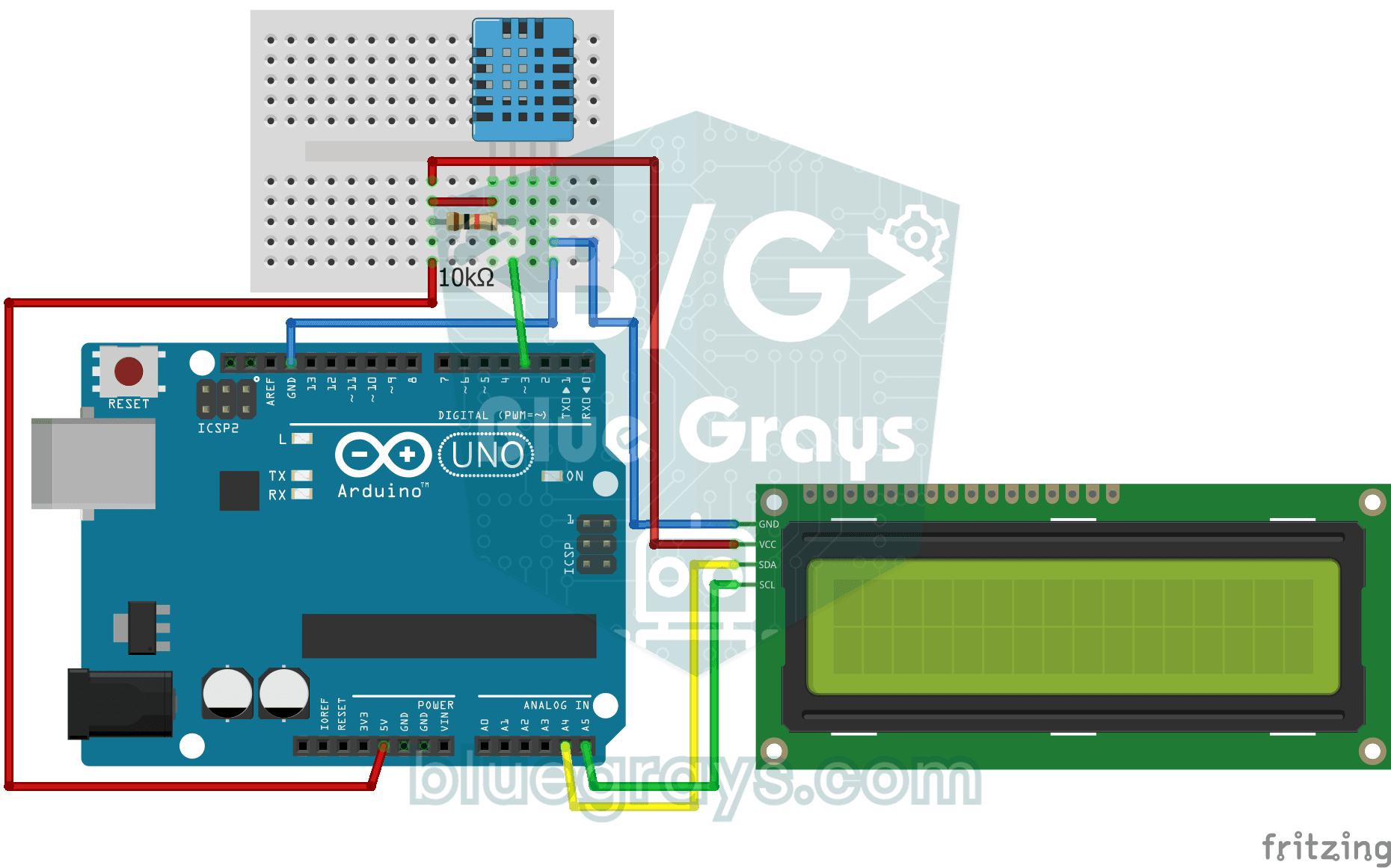
How warm is your room, and is the air humid or dry? The DHT11 sensor measures temperature and humidity, and the Arduino writes the values on a two-line LCD screen, refreshing every couple of seconds.
ESP32 Temperature Data Logger (DHT22 + DS1307 RTC + microSD + OLED)
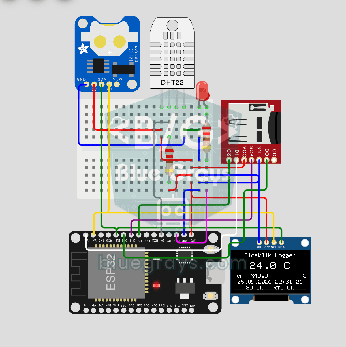
Build a timed temperature and humidity logger with the ESP32! A DHT22 sensor reads temperature and humidity once a minute, and each reading is saved to a microSD card in CSV format with a real-time stamp from the DS1307 RTC module. The OLED display shows the latest temperature, humidity, timestamp and total number of records live, in large text.

ESP32 DHT22 Temperature and Humidity (with LCD Display)
This project measures ambient temperature and humidity using a DHT22 sensor and displays the data in real time on a 16x2 I2C LCD. Data is read from the sensor using the one-wire protocol via the Adafruit DHT library. This project serves as the foundation for IoT weather stations, smart home automation, or environmental monitoring systems in greenhouses. Communication with the DHT22 is established via the ESP32's GPIO 4 pin.

ESP32 Asynchronous Web Server (with IP Display on LCD)
In this project, we’re turning the ESP32 into an asynchronous web server that you can control from your phone or computer on the same Wi-Fi network. Thanks to the ESPAsyncWebServer library, the server can process multiple requests simultaneously (unlike the classic WebServer.h, which blocks on a single request). You’ll be able to open the ESP32’s IP address in a browser and click the ON/OFF buttons (the /on and /off routes) to turn the LED connected to GPIO 5 on and off.

ESP32 Wi-Fi STA Connection (with LCD Screen)
In this project, we connect the ESP32 to the home Wi-Fi network in Station (STA) mode in a secure, fault-tolerant manner. We store the SSID and password in a separate secrets.h file to prevent leaking to Git, set up an auto-reconnect mechanism, and display the RSSI signal level and IP address on an I2C LCD screen. The internal LED works as a status indicator. It is a production-grade connection manager.
One-Way Communication Between 2 Arduinos
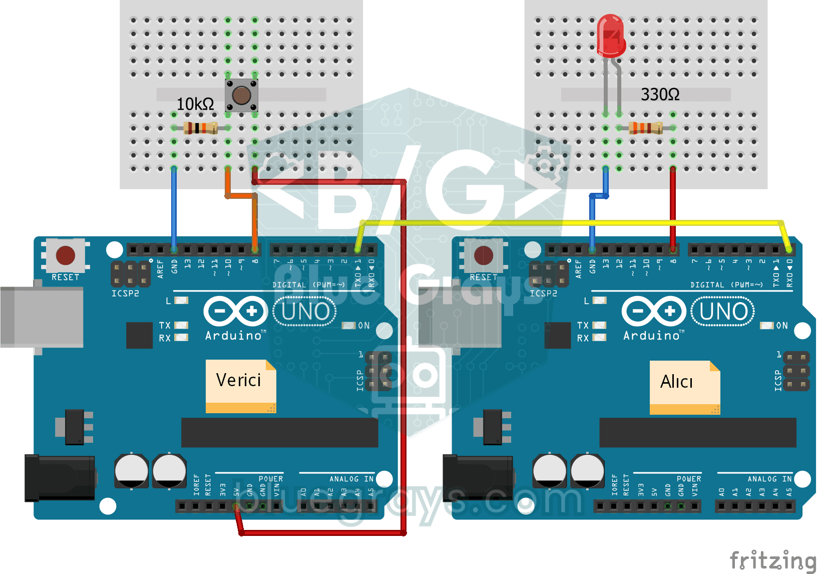
You get two Arduinos talking over a single wire: press the button on one and the LED on the other lights up, press it again and it goes off.