
PCA9685 Arduino Guide: 16-Channel Servo Driver Tutorial
PCA9685 Arduino wiring: I2C address 0x40, external servo power, pulse width calibration, and chaining boards for robot arm and hexapod spider robot code.

The PCA9685 is a 12-bit PWM driver board that can drive 16 servo motors independently and at the same time over a single I2C bus. On an Arduino Uno the Servo library manages at most 12 servos and keeps a timer completely busy while doing it; you run out of pins and the servos start to jitter. The PCA9685 generates the pulses with its own internal oscillator, so your microcontroller only has to say "move this channel to this position". You'll find this board in almost every multi-joint project: robot arms, spider robots, animatronic eyes or pan-tilt camera mounts.
In this guide you'll learn the PCA9685 Arduino wiring, why you must power servos from a separate supply, how to calibrate the pulse width to find each servo's real 0 and 180 degree values, and how to chain boards with the address jumpers. Then we'll build an 18-servo spider robot with two boards, a potentiometer-controlled robot arm with an ESP32, and a library-free MicroPython driver for the Raspberry Pi Pico. If you're new to how servo motors work, check out What Is a Servo Motor? first.
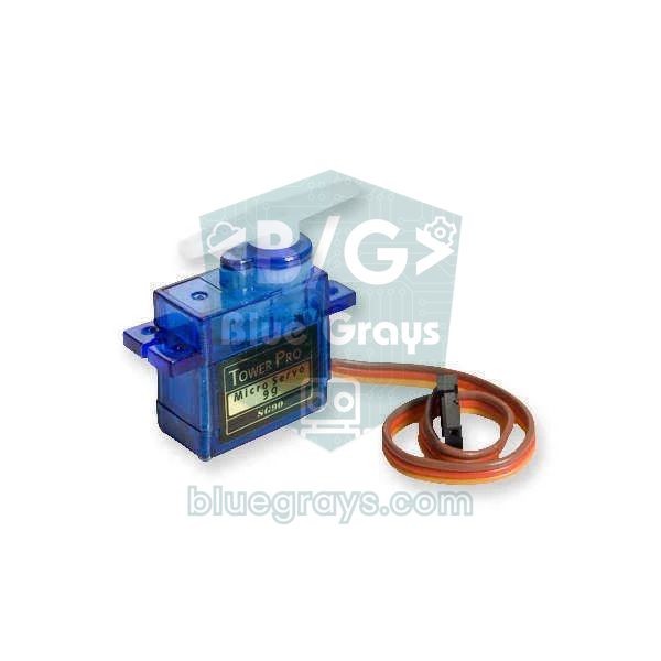
What is the PCA9685 and how does it work?
The PCA9685 is actually a chip NXP designed for driving LEDs, but because its frequency is adjustable it works perfectly with servos too. Inside it has a 25 MHz oscillator and a 12-bit counter shared by all channels; one PWM period is divided into 4096 steps (ticks). For each channel you write two numbers: the step where the signal goes high (ON) and the step where it goes low (OFF). For servos the frequency is set to 50 Hz, so the period is 20 ms. One step lasts 20 ms / 4096 ≈ 4.88 µs, so to convert the pulse width you want into ticks, use tick = pulse (µs) / 4.88. For example, the 1.5 ms centre pulse is 1500 / 4.88 ≈ 307 ticks. Once a channel is set, the board keeps generating the signal on its own; even while the Arduino is busy with other work, the servo holds its position.
| Feature | Value |
|---|---|
| Chip | NXP PCA9685 |
| Channels | 16 independent PWM outputs |
| Resolution | 12 bit (4096 steps per period) |
| PWM frequency | About 24–1526 Hz (50 Hz for servos) |
| Communication | I2C, up to 1 MHz |
| Default address | 0x40 (0x40–0x7F with the A0–A5 jumpers) |
| Logic supply (VCC) | 2.3–5.5 V |
| Servo supply (V+) | External, usually 5–6 V depending on the servo |
| Output current | 25 mA sink, 10 mA source per channel (signal only) |
| On the board | Most modules have SDA/SCL pull-up resistors and 220 Ω series resistors on the outputs |
| Pulse width | Ticks @ 50 Hz | Typical servo position |
|---|---|---|
| 0.5 ms (500 µs) | ≈ 102 | About 0° for an SG90 |
| 1.0 ms (1000 µs) | ≈ 205 | Standard 0° (narrow-range servos) |
| 1.5 ms (1500 µs) | ≈ 307 | Centre position (90°) |
| 2.0 ms (2000 µs) | ≈ 410 | Standard 180° |
| 2.4 ms (2400 µs) | ≈ 492 | About 180° for an SG90 |
PCA9685 wiring: Arduino Uno, ESP32 and Pico
| PCA9685 pin | Arduino Uno | ESP32 | Raspberry Pi Pico |
|---|---|---|---|
| GND | GND | GND | GND |
| VCC (logic) | 5V | 3V3 | 3V3(OUT) |
| SDA | A4 | GPIO 21 | GP4 |
| SCL | A5 | GPIO 22 | GP5 |
| OE | Leave open (pulled to GND on the board) | Leave open | Leave open |
| V+ (screw terminal) | Positive of the external 5–6 V supply | Positive of the external 5–6 V supply | Positive of the external 5–6 V supply |
| GND (screw terminal) | Negative of the external supply (common with GND on the board) | Negative of the external supply (common with GND on the board) | Negative of the external supply (common with GND on the board) |
External power: how much current do servos draw?
An idle servo draws only 5–10 mA, but while moving, and especially when straining under load (stall), the current shoots up. A stalled SG90 can draw 600–700 mA and an MG996R over 2 A. When all the joints of a robot arm start moving at once, these peak currents add up and a weak supply's voltage sags; the result is twitching, randomly jumping servos and a resetting Arduino. A practical rule: multiply the number of servos that move at the same time by the peak current and pick a supply that can deliver at least half of that continuously. A 5 V 3 A adapter is good for a six-SG90 robot arm, and a 5–6 V 8–10 A supply, or a powerful UBEC from the RC world, for an 18-servo spider robot.
| Servo | Idle | Moving | Stalled | Supply |
|---|---|---|---|---|
| SG90 (9 g, plastic gears) | ≈ 10 mA | 100–250 mA | ≈ 650 mA | 4.8–6 V |
| MG90S (metal gears) | ≈ 10 mA | 150–300 mA | ≈ 700 mA | 4.8–6 V |
| MG996R (standard size) | ≈ 10 mA | 500–900 mA | ≈ 2.5 A | 4.8–7.2 V |
Step by step first run: spin 4 servos together
- Open the Library Manager in the Arduino IDE, search for the Adafruit PWM Servo Driver library and install it.
- Connect the board's VCC, GND, SDA and SCL pins to the Arduino as in the table above; leave the OE pin open.
- Plug the servos into channels 0, 1, 2 and 3. The orange or yellow signal wire of the plug must line up with the PWM row, the red with the V+ row and the brown or black with the GND row.
- Connect the external 5 V supply to the screw terminal: positive to V+, negative to GND.
- First power the Arduino over USB and upload the code, then switch on the servo supply. If you're not sure of the board's address, confirm that 0x40 shows up with an I2C scanner sketch.
1#include <Wire.h>
2#include <Adafruit_PWMServoDriver.h>
3
4Adafruit_PWMServoDriver pwm = Adafruit_PWMServoDriver();  // varsayılan adres 0x40 / default address 0x40
5
6const int SERVO_MIN = 110;   // 0 derece için tick (kalibre et) / tick for 0 degrees (calibrate)
7const int SERVO_MAX = 500;   // 180 derece için tick (kalibre et) / tick for 180 degrees (calibrate)
8
9void servoAci(uint8_t kanal, int aci) {
10  aci = constrain(aci, 0, 180);
11  int tick = map(aci, 0, 180, SERVO_MIN, SERVO_MAX);
12  pwm.setPWM(kanal, 0, tick);   // darbe 0'da başlar, tick'te biter / pulse starts at 0, ends at tick
13}
14
15void setup() {
16  pwm.begin();
17  pwm.setOscillatorFrequency(27000000);   // iç osilatör düzeltmesi / internal oscillator trim
18  pwm.setPWMFreq(50);                     // servo için 50 Hz (20 ms) / 50 Hz for servos (20 ms)
19  delay(10);
20}
21
22void loop() {
23  for (int aci = 0; aci <= 180; aci += 2) {        // 0 -> 180 derece / degrees
24    for (uint8_t k = 0; k < 4; k++) servoAci(k, aci);
25    delay(15);
26  }
27  for (int aci = 180; aci >= 0; aci -= 2) {        // 180 -> 0 derece / degrees
28    for (uint8_t k = 0; k < 4; k++) servoAci(k, aci);
29    delay(15);
30  }
31}
pwm.begin() initialises the board and setPWMFreq(50) sets the period to 20 ms for servos. The setOscillatorFrequency(27000000) line comes from the Adafruit examples: although the chip's internal oscillator is 25 MHz on paper, in reality it varies between 23 and 27 MHz, and the library calculates the prescaler from this value. The real work is done by setPWM(channel, on, off); if you leave on at 0 and write the tick count to off, the pulse starts at the beginning of the period and ends at that step. The servoAci() function uses map() to convert 0–180 degrees into the SERVO_MIN–SERVO_MAX range. The library also has a writeMicroseconds(channel, µs) function that takes the pulse directly in microseconds, but since its accuracy depends on the oscillator setting, working in ticks and calibrating each servo is more reliable.
Pulse width calibration: find each servo's real limits
Servo makers quote the standard 1–2 ms range, but in reality every servo is different: one SG90 turns a full 180 degrees between 0.5 and 2.4 ms while another may only reach 170 degrees. If you blindly use the values in the table, the servo hits its mechanical stop at the end of travel, buzzes, draws unnecessary current and wears its gears over time. The calibration code below sends the tick value you type into the Serial Monitor to channel 0. Start around 300 and decrease the value in steps of 10; note the point where the servo stops turning or starts to buzz, and take 5–10 ticks above it as SERVO_MIN. Do the same in the other direction to find SERVO_MAX. In a robot arm or spider robot every joint is a separate servo, so the cleanest method is to repeat this measurement for each servo and store the values in an array.
1#include <Wire.h>
2#include <Adafruit_PWMServoDriver.h>
3
4Adafruit_PWMServoDriver pwm = Adafruit_PWMServoDriver(0x40);
5
6void setup() {
7  Serial.begin(115200);                   // Seri Monitör: 115200, Yeni satır / Serial Monitor: 115200, Newline
8  pwm.begin();
9  pwm.setOscillatorFrequency(27000000);
10  pwm.setPWMFreq(50);
11  pwm.setPWM(0, 0, 307);                  // yaklaşık orta konum / roughly center position
12  Serial.println(F("Tick degeri yaz (80-650) / Enter tick value (80-650)"));
13}
14
15void loop() {
16  if (Serial.available()) {
17    int ticks = Serial.parseInt();        // yazılan sayıyı oku / read the typed number
18    if (ticks >= 80 && ticks <= 650) {    // güvenli aralık / safe range
19      pwm.setPWM(0, 0, ticks);
20      Serial.print(F("Tick: "));
21      Serial.println(ticks);
22    }
23    while (Serial.available()) Serial.read();   // kalan karakterleri at / discard leftover characters
24  }
25}
Chaining multiple PCA9685 boards
Along the top edge of each board there are six address jumpers (solder pads) from A0 to A5. With all of them open the address is 0x40; when you bridge a pad with solder, the corresponding bit becomes 1 and that bit's value is added to the address. This means that in theory 62 boards, or 992 servos, can share the same I2C bus. Because the 6-pin headers on both sides of the boards are wired in parallel, a short cable from the first board to the second is enough; SDA, SCL, VCC and GND are carried down the chain. In code you create a separate object for each board and pass its address to the constructor. Avoid address 0x70, because it is the chip's default "All Call" address. To learn I2C addressing in more depth, see What Is I2C?.
| Bridged jumpers | Address | Example use |
|---|---|---|
| None | 0x40 | Board 1 (servos 0–15) |
| A0 | 0x41 | Board 2 (servos 16–31) |
| A1 | 0x42 | Board 3 |
| A0 + A1 | 0x43 | Board 4 |
| A2 | 0x44 | Board 5 |
| All of A0–A5 | 0x7F | Last address |
Spider robot: 18 servos with two PCA9685 boards
On a six-legged spider robot (hexapod) every leg has three joints: the hip (coxa) attached to the body, the thigh (femur) that lifts the leg up and down, and the knee (tibia) whose tip touches the ground. 6 × 3 = 18 servos exceeds the 16 channels of a single board, so two boards are chained: the left legs go to the board at address 0x40 and the right legs to the board at 0x41 with the A0 jumper bridged. A four-legged spider robot (quadruped) uses 12 servos and fits on a single board with 4 channels to spare. The code below addresses the servos with a single number from 0 to 17, stands the robot up and moves the knees in turn. Positioning the servos one at a time with a 100 ms wait between them prevents the current surge that would occur if all 18 servos rose at once. For real walking, a tripod gait lifts three legs at a time while the other three carry the body.
1#include <Wire.h>
2#include <Adafruit_PWMServoDriver.h>
3
4Adafruit_PWMServoDriver sol = Adafruit_PWMServoDriver(0x40);   // sol bacaklar / left legs
5Adafruit_PWMServoDriver sag = Adafruit_PWMServoDriver(0x41);   // sağ bacaklar (A0 lehimli) / right legs (A0 bridged)
6
7const int SERVO_MIN = 110;
8const int SERVO_MAX = 500;
9
10// servo no 0-17: 0-8 sol kart, 9-17 sağ kart / servo no 0-17: 0-8 left board, 9-17 right board
11void servoYaz(uint8_t no, int aci) {
12  int tick = map(constrain(aci, 0, 180), 0, 180, SERVO_MIN, SERVO_MAX);
13  if (no < 9) sol.setPWM(no, 0, tick);
14  else        sag.setPWM(no - 9, 0, tick);
15}
16
17void setup() {
18  sol.begin();
19  sol.setOscillatorFrequency(27000000);
20  sol.setPWMFreq(50);
21  sag.begin();
22  sag.setOscillatorFrequency(27000000);
23  sag.setPWMFreq(50);
24  Wire.setClock(400000);                // hızlı I2C / fast I2C
25
26  for (uint8_t i = 0; i < 18; i++) {    // ayağa kalk: tüm eklemler 90 derece / stand up: all joints at 90 degrees
27    servoYaz(i, 90);
28    delay(100);                         // akım sıçramasını azalt / reduce current surge
29  }
30}
31
32void loop() {
33  for (uint8_t bacak = 0; bacak < 6; bacak++) {   // her bacağın dizini sırayla oynat / move each leg's knee in turn
34    uint8_t diz = bacak * 3 + 2;                  // her bacağın 3. servosu / third servo of each leg
35    servoYaz(diz, 60);
36    delay(300);
37    servoYaz(diz, 90);
38    delay(300);
39  }
40}
ESP32 and PCA9685: potentiometer-controlled robot arm
On the ESP32 the same Adafruit library works without changes; the I2C pins are GPIO 21 (SDA) and GPIO 22 (SCL). In this example we control a four-joint robot arm (base, shoulder, elbow, gripper) with four potentiometers. Connect the outer pins of the potentiometers to 3V3 and GND and the middle pins to GPIO 34, 35, 32 and 33 in the ADC1 group; since ADC2 pins can't be read while Wi-Fi is on, this choice also makes it easier to add wireless control later. The ESP32's ADC gives values from 0 to 4095. Instead of jumping each joint straight to the target angle, the code moves it 10 percent of the remaining difference closer on every loop; this simple smoothing reduces jerking and sudden current draw. For mechanical design and joint order, Arduino Robot Arm is a good place to start.
1#include <Wire.h>
2#include <Adafruit_PWMServoDriver.h>
3
4Adafruit_PWMServoDriver pwm = Adafruit_PWMServoDriver(0x40);
5
6const int SERVO_MIN = 110;                    // kalibrasyondan / from calibration
7const int SERVO_MAX = 500;
8const int POT_PINS[4] = {34, 35, 32, 33};     // taban, omuz, dirsek, kıskaç / base, shoulder, elbow, gripper
9float konum[4] = {90, 90, 90, 90};            // anlık açılar / current angles
10
11void setup() {
12  Wire.begin(21, 22);                         // SDA, SCL
13  pwm.begin();
14  pwm.setOscillatorFrequency(27000000);
15  pwm.setPWMFreq(50);
16}
17
18void loop() {
19  for (int i = 0; i < 4; i++) {
20    int hedef = map(analogRead(POT_PINS[i]), 0, 4095, 0, 180);    // 12 bit ADC -> açı / 12-bit ADC -> angle
21    konum[i] += (hedef - konum[i]) * 0.1f;                        // yumuşak geçiş / smoothing
22    int tick = map((long)konum[i], 0, 180, SERVO_MIN, SERVO_MAX);
23    pwm.setPWM(i, 0, tick);
24  }
25  delay(20);                                  // her 20 ms'de bir güncelle / update every 20 ms
26}
Raspberry Pi Pico and PCA9685 with MicroPython
MicroPython has no ready-made PCA9685 driver in its core, but the chip is so easy to control with a few registers that you can write the driver yourself. The MODE1 register (0x00) wakes the chip, the PRESCALE register (0xFE) sets the frequency, and each channel's four-byte ON/OFF registers start at address 0x06 and step forward four at a time. The prescaler value is calculated with prescale = oscillator / (4096 × frequency) − 1 and can only be written while the chip is in sleep mode. Power the board from the Pico's 3V3(OUT) pin and connect SDA to GP4 and SCL to GP5. If you're new to MicroPython, MicroPython Basics will help.
1from machine import Pin, I2C
2import time
3
4class PCA9685:
5    def __init__(self, i2c, addr=0x40):
6        self.i2c = i2c
7        self.addr = addr
8        self._yaz(0x00, 0x00)                   # MODE1: uykudan çık / wake up
9        time.sleep_ms(5)
10
11    def _yaz(self, reg, deger):
12        self.i2c.writeto_mem(self.addr, reg, bytes([deger]))
13
14    def _oku(self, reg):
15        return self.i2c.readfrom_mem(self.addr, reg, 1)[0]
16
17    def frekans(self, hz, osc=27000000):        # Adafruit ile aynı osilatör varsayımı / same oscillator assumption as Adafruit
18        prescale = int(osc / (4096 * hz) + 0.5) - 1
19        eski = self._oku(0x00)
20        self._yaz(0x00, (eski & 0x7F) | 0x10)   # uyku kipi / sleep mode
21        self._yaz(0xFE, prescale)               # ön bölücü / prescaler
22        self._yaz(0x00, eski)
23        time.sleep_ms(5)
24        self._yaz(0x00, eski | 0xA0)            # yeniden başlat + otomatik artış / restart + auto-increment
25
26    def pwm(self, kanal, on, off):
27        reg = 0x06 + 4 * kanal                  # LEDn_ON_L yazmacı / LEDn_ON_L register
28        self.i2c.writeto_mem(self.addr, reg, bytes([on & 0xFF, on >> 8, off & 0xFF, off >> 8]))
29
30SERVO_MIN = 110                                 # 0 derece / 0 degrees
31SERVO_MAX = 500                                 # 180 derece / 180 degrees
32
33def servo_aci(pca, kanal, aci):
34    aci = max(0, min(180, aci))
35    tick = SERVO_MIN + (SERVO_MAX - SERVO_MIN) * aci // 180
36    pca.pwm(kanal, 0, tick)
37
38i2c = I2C(0, sda=Pin(4), scl=Pin(5), freq=400000)
39pca = PCA9685(i2c)
40pca.frekans(50)                                 # servo için 50 Hz / 50 Hz for servos
41
42while True:
43    for aci in range(0, 181, 2):                # 0 -> 180 derece / degrees
44        for k in range(4):
45            servo_aci(pca, k, aci)
46        time.sleep_ms(15)
47    for aci in range(180, -1, -2):              # 180 -> 0 derece / degrees
48        for k in range(4):
49            servo_aci(pca, k, aci)
50        time.sleep_ms(15)
PCA9685 project ideas
- Robot arm: control a 4–6 joint arm with potentiometers or a joystick, and save the movements to EEPROM to play them back.
- Spider robot: build a walking robot with 12 servos on four legs or 18 servos on six legs; at an advanced level, use inverse kinematics to calculate the foot tip coordinates.
- Animatronic eyes and face: move 6–8 small servos in sync for eyelids, pupils and eyebrows.
- Pan-tilt camera mount: turn an ESP32-CAM module horizontally and vertically with two servos and steer it over Wi-Fi.
- Servo choreography: move 32 servos arranged in a circle with two boards in wave and spiral patterns.
- 16-channel LED dimmer: the PCA9685 is really an LED driver; raise the frequency to 1000 Hz and set the brightness of 16 LEDs without flicker. You use the same PWM logic here.
Common mistakes and how to fix them
| Symptom | Likely cause | Fix |
|---|---|---|
| Servos don't move at all | No V+ supply, or setPWMFreq wasn't called | Connect external power to the terminal and make sure setPWMFreq(50) is in setup |
| Servos jitter and jump randomly | Supply current is too low, wires are thin | Use a stronger supply, thick wires and a 470–1000 µF capacitor on the V+ line |
| Arduino resets when the servos move | Servos are powered from the Arduino's 5V pin | Power the servos only from V+ and join the GNDs |
| Servo buzzes and heats up at the end of travel | SERVO_MIN or SERVO_MAX is beyond the mechanical limit | Find the limits with the calibration code and stay 5–10 ticks inside |
| Code freezes or the board isn't found | Wrong address, SDA and SCL swapped, two boards at the same address | Run an I2C scanner and check the address jumpers |
| Servos jump hard at power-up | All servos go to position at the same time | Start the servos one by one with a short delay between them |
As soon as you have more than two or three servos, the PCA9685 is a cheap and sturdy board that puts your project in order: once you've set up the power properly and calibrated each servo, the rest is just writing angles. For stronger joints you can plug MG996R servos into the same board, and FS90R servos for continuously rotating wheels. In the BlueGrays app you'll find projects such as a 32-servo circle choreography, servo control with a potentiometer and joystick, and an ESP32 RFID door lock, with step-by-step circuit diagrams and code.
Frequently asked questions
How many servos can you control with a PCA9685?
A single PCA9685 board drives 16 servos independently. Since up to 62 boards can be chained on the same I2C bus with the address jumpers, in theory 992 servos can be controlled. In practice the limit isn't the boards but the current your power supply can deliver to the servos.
Why does a servo connected to a PCA9685 jitter?
The most common cause is an inadequate power supply; the V+ voltage drops while the servos move. The second cause is uncalibrated SERVO_MIN and SERVO_MAX values making the servo push against its mechanical limit. A strong supply, thick wires, a large capacitor on the V+ line and correct limit values usually fix the problem.
What is the difference between VCC and V+ on the PCA9685?
VCC is the chip's logic supply; it connects to 5V on an Arduino Uno and to 3V3 on the ESP32 and Pico, and draws very little current. V+ is the servos' power rail and is fed from an external 5–6 V supply. Mixing them up either stops the board working or resets the microcontroller.
How do you change the PCA9685 I2C address?
You bridge one or more of the A0–A5 solder pads on the board. With none bridged the address is 0x40; bridging A0 gives 0x41 and bridging A1 gives 0x42. In code, just create the object with the new address, such as Adafruit_PWMServoDriver(0x41).
Does the PCA9685 work with the ESP32?
Yes, the Adafruit PWM Servo Driver library works on the ESP32 without changes. Connect SDA to GPIO 21 and SCL to GPIO 22 and power the board's VCC from 3V3 so the I2C lines stay at 3.3 V. The servo signal is then 3.3 V; most standard servos detect this level without problems.
What can you use the PCA9685 for besides servos?
The chip is really a 16-channel LED driver; if you raise the frequency to around 1000 Hz you can set LED brightness in 4096 steps. It can also control the speed of small DC motors through a transistor or MOSFET. The channels don't drive big loads directly; they only produce a control signal.
Projects to build after reading this
See all projects
Servo Circle Choreography - Animated Patterns with 32 Servos
A visual animation project driven by 32 servo motors arranged in a circle on an Arduino Mega. The servos are managed in a single array, connected to the Mega's pins 22–53, and perform four motion sequences: a chaotic jitter at random angles, a synchronized sweep, a wave travelling around the circle and a compass needle swinging left and right.
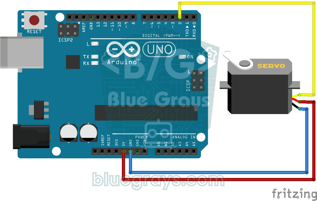
Using a Servo Motor
The arm of a small servo motor turns to three positions in turn: all the way to the start, right to the middle and all the way to the end, waiting two seconds at each stop.
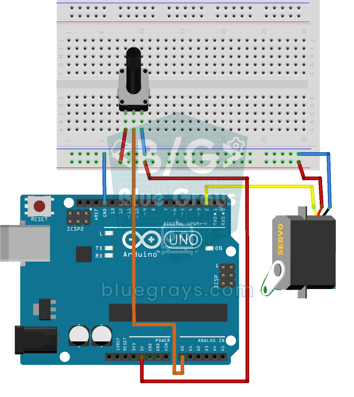
Servo Motor Operation with Potentiometer
As you turn the potentiometer knob, the servo motor's arm turns right along with it: one end of the knob means zero degrees, the other end means half a turn.
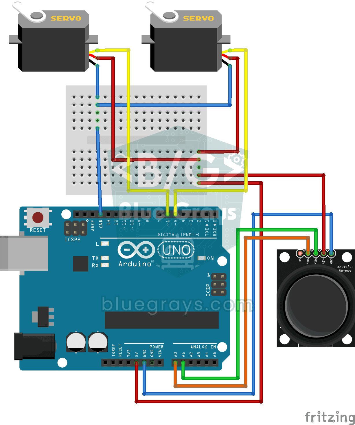
Servo Control with Joystick
Steer two motors with a joystick, just like turning a security camera. Push the stick left or right and the bottom servo motor slowly turns, push it up or down and the top servo tilts up and down…

ESP32 Servo Motor (Potentiometer Control)
In this project, we control an SG90 servo motor using a potentiometer. We adjust the servo angle by mapping the analog value read from the potentiometer to the 0–180-degree range. The ESP32Servo library generates servo signals on suitable output-capable GPIO pins of the ESP32; this project uses GPIO 18. This is a fundamental control method for robotic arms, camera gimbals, and automatic door mechanisms.

ESP32 RFID Door Lock (RC522 + Servo + OLED + Buzzer + LED)
We build a smart door lock with an ESP32, an RC522 RFID module, an SG90 servo, an SSD1306 OLED display, an active buzzer and 2 LEDs. When a card is scanned, its UID is checked against the authorized cards defined in the code; if it matches, the servo unlocks (green LED + 2 short beeps) and locks again after 5 seconds. An unknown card lights the red LED, gives 3 quick beeps and shows its UID on the OLED.
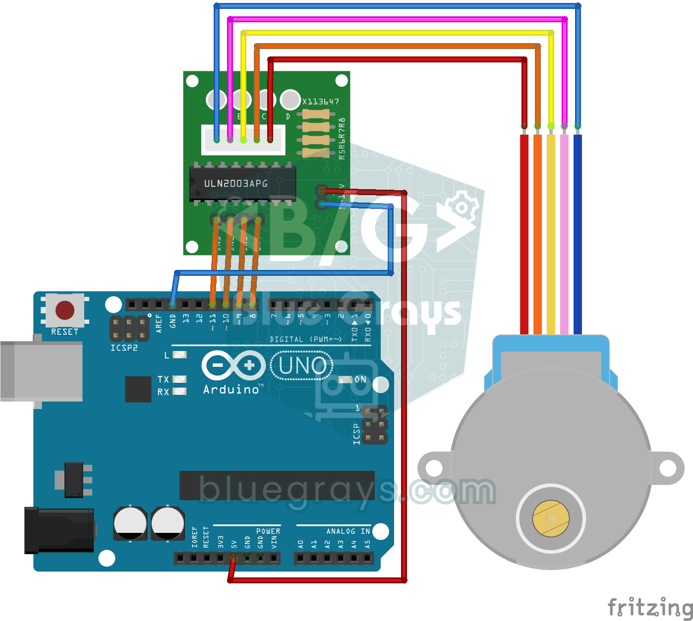
360-Degree Servo from a Stepper Motor
Teach an ordinary stepper motor to go to any angle you want, all the way around the circle.