
Arduino Robotic Arm: Servo Choice, Torque, PCA9685 and Bluetooth
Build an Arduino robotic arm step by step: MDF or 3D-printed frame, MG996R torque math, pot and joystick control, record/playback, PCA9685 and Bluetooth code.
An Arduino robotic arm is a desktop-sized robot whose servo-driven joints let it grab an object, lift it, swing around and put it down somewhere else. Built from a base, shoulder, elbow, wrist and gripper, it teaches mechanical design, motor selection, power management and coding in a single project. Better still, you can build one at home with an Arduino Uno, a few servos and MDF or 3D-printed parts, and run a small copy of a factory robot arm right on your desk.
In this guide we cover 4 and 6-axis robot arms from start to finish: choosing a frame material, a torque calculation to pick between the SG90, MG90S and MG996R, an external 5 V supply, control with potentiometers and joysticks, recording and replaying movements, the 16-channel PCA9685 servo driver, Bluetooth control from your phone, and the fixes for the two most common problems: jitter and resets. If you're not sure how a servo works, start with What Is a Servo Motor? first.
How does a robot arm work, and how many axes do you need?
Think of a robot arm as a human arm. Every joint has a servo motor, and the Arduino tells each servo "go to this angle". Thanks to the potentiometer inside, the servo knows where its shaft is and holds that angle even under load. By changing the joint angles together, you move the gripper to the point you want. The number of independent movements an arm can make is called its degrees of freedom (DOF), or simply its axes.
| Joint | Movement | Load | Recommended servo |
|---|---|---|---|
| Base (waist) | Swings the arm left and right | Lifts nothing but carries the whole arm | MG996R + bearing |
| Shoulder | Raises the arm forward and back | The most heavily loaded joint | MG996R or a 20 kg·cm class servo |
| Elbow | Bends the forearm | Medium to high | MG996R |
| Wrist (pitch) | Sets the gripper angle | Low | MG90S |
| Wrist roll | Rotates the gripper around its axis | Very low | MG90S or SG90 |
| Gripper | Grabs and releases the object | Clamping force | SG90 or MG90S |
Most "6-axis robot arm" kits on the market have 6 servos; since the gripper doesn't count as an axis, technically they're a 5-DOF arm plus a gripper. For your first arm, a 4-axis design (base, shoulder, elbow, gripper) is the best start: 4 servos, 4 potentiometers and an Arduino Uno are enough, the wiring stays simple and torque problems are rare. Wrist joints help when you need to keep the gripper level or grab objects from different angles; once you move to 5–6 servos, a PCA9685 driver becomes almost essential.
Parts list
| Part | 4-axis arm | 6-servo arm | Note |
|---|---|---|---|
| Controller | Arduino Uno or Nano | Arduino Uno, Nano or ESP32 | The Nano's extra A6 and A7 inputs allow more pots |
| Servo motors | 4× SG90 or MG90S | 3× MG996R + 3× MG90S | Check your choice with the torque calculation below |
| Servo driver | Not needed | PCA9685 16-channel module | Only 2 signal wires over I2C |
| Power supply | 5 V 3 A adapter | 5–6 V adapter, at least 5 A | Servos are never powered from the Arduino |
| Capacitor | 470–1000 µF, 16 V | 1000–2200 µF, 16 V | On the servo supply rail, mind the polarity |
| Controls | 4× 10 kΩ potentiometers | 2× joystick modules or an HC-05 | You can also use both |
| Buttons | 2 (record, play) | The joystick buttons are enough | No extra resistors with INPUT_PULLUP |
| Mechanics | 3 mm MDF or 3D-printed parts | 4 mm MDF, 3D printing or aluminium brackets | 608 bearing, M3 bolts and lock nuts |
Mechanical design: MDF or 3D printing?
| Material | Pros | Cons | Best for |
|---|---|---|---|
| 3–4 mm MDF (laser cut) | Cheap, light, easy to screw and glue | Sensitive to moisture, screw holes widen over time | MeArm-style first arms, school projects |
| 3 mm acrylic | Looks great, unaffected by moisture | Brittle; can crack when you tighten screws | Display and showcase builds |
| 3D printing (PLA / PETG) | Complex parts, servo pockets to exact size | Long print times; PLA creeps in heat and under constant load | Your own designs; PETG for load-bearing parts |
| Aluminium bracket kit | Very rigid, ready-made parts for the MG996R | Heavy and expensive, adds load to the shoulder | 6-servo arms meant to lift heavier objects |
| Cardboard, craft sticks | Almost free, fast prototyping | Flimsy, joints develop play | Testing dimensions, first builds with kids |
- Keep the arm short and light: The load on the shoulder grows in direct proportion to distance. Making the arm 24 cm instead of 30 cm cuts the shoulder torque by about a fifth.
- Put the heavy servos near the base: Moving the elbow servo down to the shoulder and driving the elbow through a push rod (parallel linkage) is a clever trick used by arms like the MeArm; the shoulder no longer has to lift that servo.
- Use a bearing in the base: Don't hang the whole arm's weight on the base servo's shaft. A 608 bearing (8 mm bore, 22 mm outside diameter, 7 mm thick; the classic skateboard bearing) or a lazy Susan bearing carries the load, and the servo only turns it.
- Support joints on both sides: While the servo holds the joint on the horn side, add a pivot on the opposite side with an M3 bolt and a lock nut. That way the servo shaft takes no bending load and the gears last much longer.
- Use metal horns: Fit a 25-tooth (25T) round metal horn on each MG996R and secure it to the shaft with the centre screw. Plastic horns slip and strip their splines on heavily loaded joints.
- Add rubber to the gripper fingers: A thin strip of rubber on the fingertips lets the gripper hold objects without slipping and with less clamping force.
Choosing servos: SG90, MG90S or MG996R?
| Model | Torque | Speed (per 60°) | Weight | Gears | Stall current | Role in a robot arm |
|---|---|---|---|---|---|---|
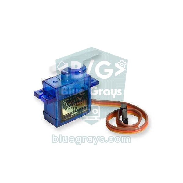
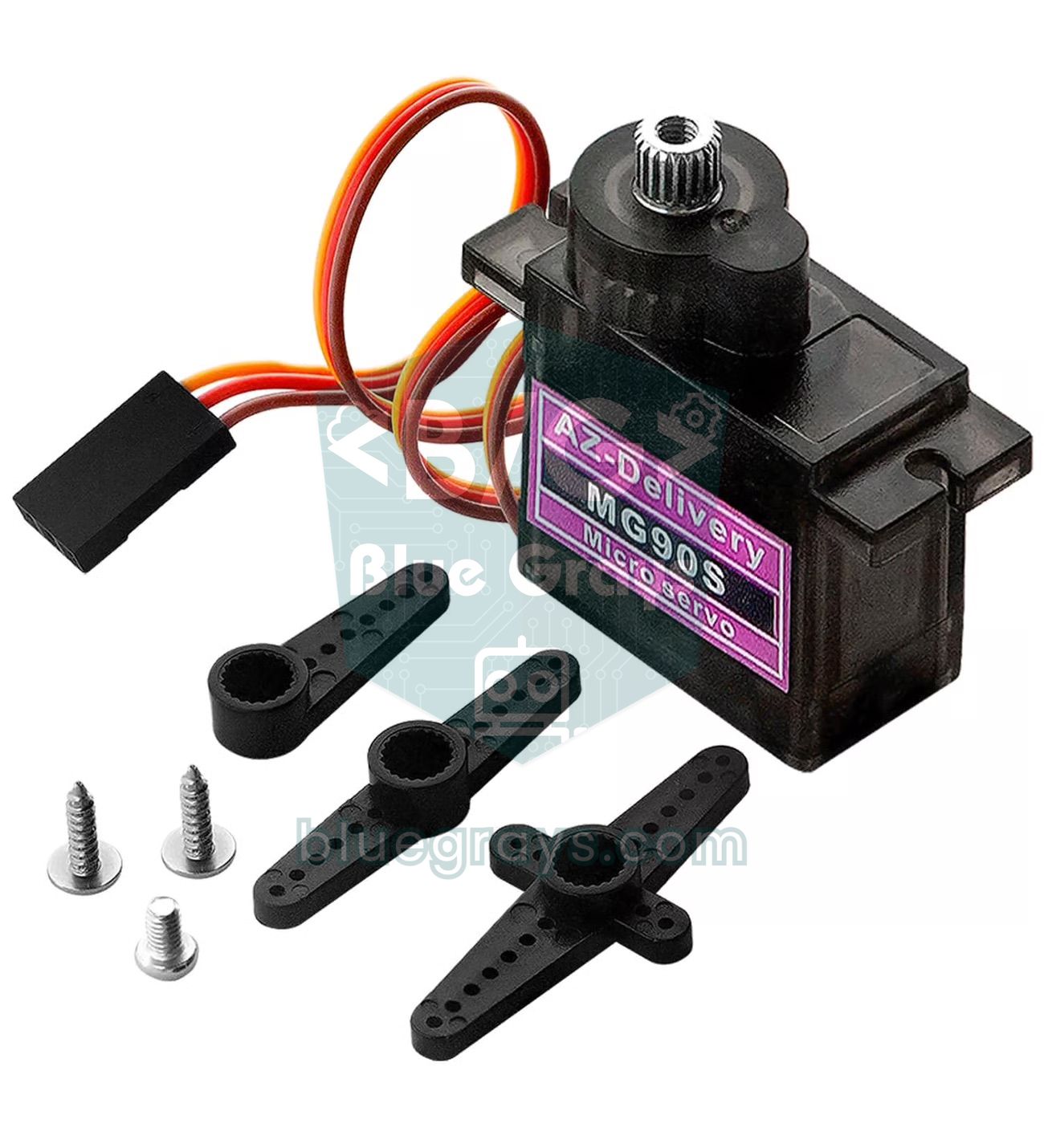
| SG90 | 1.8 kg·cm (4.8 V) | 0.10 s (4.8 V) | 9 g | Plastic | About 0.6–0.75 A | Gripper, light wrist, small 4-axis arm |
| MG90S | 1.8 kg·cm (4.8 V), 2.2 kg·cm (6 V) | 0.10 s (4.8 V) | 13.4 g | Metal | About 0.7–1 A | Wrist, wrist roll, gripper |
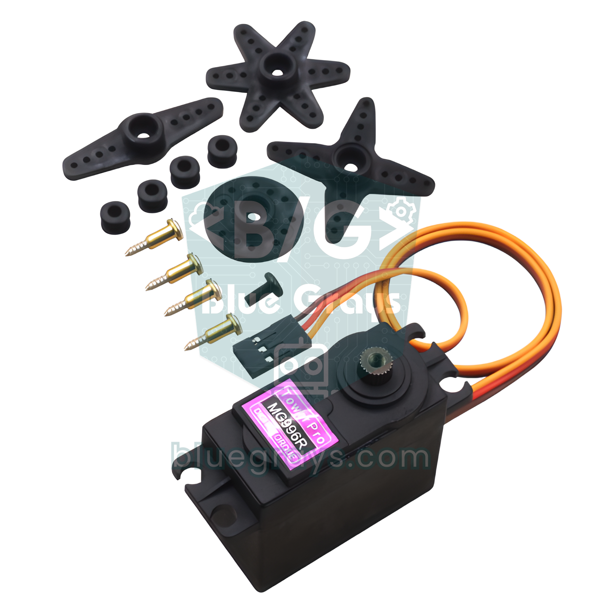
| MG996R | 9.4 kg·cm (4.8 V), 11 kg·cm (6 V) | 0.17 s (4.8 V) | 55 g | Metal | 2.5 A (6 V) | Base, shoulder, elbow |
| DS3218 | 19 kg·cm (5 V), 21.5 kg·cm (6.8 V) | 0.16 s (5 V) | 60 g | Metal | About 2–3 A | Shoulder of long or heavy arms |
The torque figure in the table is the stall torque: the maximum force the servo can deliver before its shaft stops, not a value it can work at continuously. As a servo approaches that limit, its current climbs towards the stall current, it heats up and starts to jitter. The practical rule is that the torque a joint needs should be no more than half of the servo's stall torque. Voltage matters too: the MG996R gives 9.4 kg·cm at 4.8 V and 11 kg·cm at 6 V, so the same servo gets about 17% stronger just from the supply voltage. That's why a 6 V supply makes sense for MG996R arms, but 6 V is the upper limit for the SG90 and MG90S. For wiring and limits of the MG996R, see the MG996R servo motor guide too.
Torque calculation: can the shoulder servo lift this arm?
The torque a servo has to lift is the sum of each part's mass multiplied by its horizontal distance from the joint axis: Torque (kg·cm) = Σ mass (kg) × distance (cm). The worst case is when the arm is stretched out horizontally, because every distance is at its maximum; with the arm pointing straight up, that lever arm drops to almost zero. To convert to newton metres, multiply by 0.098 (1 kg·cm ≈ 0.098 N·m). As an example, let's calculate the shoulder load of a desktop arm with 12 cm from shoulder to elbow, 12 cm from elbow to wrist, 6 cm from the wrist to the gripper tip and an MG996R at the elbow, with the gripper holding a 50 g object:
| Part | Mass | Distance from shoulder axis | Torque |
|---|---|---|---|
| Upper arm parts (MDF and bolts) | 40 g | 6 cm (centre of mass) | 0.04 × 6 = 0.24 kg·cm |
| Elbow servo (MG996R) | 55 g | 12 cm | 0.055 × 12 = 0.66 kg·cm |
| Forearm parts | 30 g | 18 cm | 0.03 × 18 = 0.54 kg·cm |
| Wrist servo + gripper (MG90S, SG90 and parts) | 50 g | 25 cm | 0.05 × 25 = 1.25 kg·cm |
| Object being held | 50 g | 30 cm | 0.05 × 30 = 1.50 kg·cm |
| Total | 225 g | — | 4.19 kg·cm (≈ 0.41 N·m) |
Holding still, this arm needs 4.19 kg·cm at the shoulder. To cover the extra load from accelerating and braking, and to keep the servo well away from stall, multiply by 2: 8.4 kg·cm. So the shoulder needs at least an MG996R (9.4 kg·cm at 4.8 V, 11 kg·cm at 6 V); the 1.8–2.2 kg·cm of an SG90 or MG90S won't even budge this arm. Doing the same for the elbow, the forearm (0.03 × 6), wrist and gripper (0.05 × 13) and object (0.05 × 18) add up to 1.73 kg·cm, or 3.5 kg·cm with the safety margin, so the elbow needs an MG996R as well. At the wrist only the gripper and object remain, so the load is about 0.4 kg·cm and an MG90S is plenty. The same calculation tells you the heaviest object the arm can carry: increase the object's mass, recalculate the total and stay below half the servo's torque.
Power supply: why aren't servos powered from the Arduino?
Most robot arm problems come from the power supply. An MG996R draws 0.5–0.9 A while moving and up to 2.5 A when stalled; even a small SG90 can exceed 0.6 A at stall. When an Arduino Uno runs from USB, the total current available from its 5V pin is about 500 mA, the USB limit, and the board itself uses part of that. When three big servos start moving at once, the voltage collapses, the microcontroller resets and the arm jumps back to its start pose. The fix is to power the servos from a separate 5–6 V source and connect all the grounds together; you can keep powering the Arduino from USB or its own adapter. For supply options see the Arduino power supply guide, and to estimate how long a battery-powered arm will run, try the battery life calculator.
| Arm type | Estimated current | Recommended supply |
|---|---|---|
| Small arm with 4× SG90 or MG90S | 0.5–1 A while moving, 2–3 A peak | 5 V 3 A adapter or an LM2596 module (3 A max, about 2 A without a heatsink) |
| 6-servo arm with 3× MG996R + 3× MG90S | 2–3 A while moving, 8–10 A if all stall | 5–6 V switching adapter, at least 5 A (10 A for comfortable headroom) |
| Portable arm | Depends on the arm | 2S LiPo (7.4 V) + a 5 A or larger step-down module (UBEC) set to 6 V |
| Supplies to avoid | — | 9 V PP3 battery (can't deliver the current), the Arduino's 5V pin, 4× AA alkaline cells on an MG996R arm |
Wiring the 4-axis arm
The table below shows the Arduino Uno and Raspberry Pi Pico wiring for the potentiometer-controlled 4-axis arm; the code in this guide uses these pins. On the Uno, the Servo library can drive a servo from any digital pin, but because it uses Timer1, analogWrite stops working on pins 9 and 10 while servos are attached. You can check your board's pin layout in the Pinout tool.
| Connection | Arduino Uno | Raspberry Pi Pico |
|---|---|---|
| Base servo signal (orange wire) | D3 | GP10 |
| Shoulder servo signal | D5 | GP11 |
| Elbow servo signal | D6 | GP12 |
| Gripper servo signal | D9 | GP13 |
| Pots 1–3 wiper (base, shoulder, elbow) | A0, A1, A2 | GP26, GP27, GP28 |
| Pot 4 wiper (gripper) | A3 | None; the gripper uses the button on GP14 |
| Pot outer legs | 5V and GND | 3V3 and GND |
| Record and play buttons (other side to GND) | D7 and D8 | — |
| Servo red wire (+) | External 5–6 V positive | External 5–6 V positive |
| Servo brown wire (−) | External supply negative + Arduino GND | External supply negative + Pico GND |
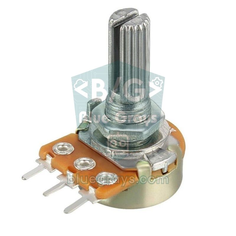
Calibrate before assembly: centre the servos
- Before fitting the horns, upload the code below; all four servos move to 90 degrees one after another and wait there.
- Hold the arm in a neutral pose (for example upper arm vertical, forearm horizontal, gripper half open), fit each horn on the spline tooth closest to that pose and fix it with the centre screw.
- Set CENTER_ONLY to false in the code, pick a joint with TEST and slowly turn the potentiometer on A0.
- Watch the angle in the Serial Monitor and write down the smallest and largest angle the joint can reach without hitting anything or stretching the cables.
- Set the gripper's closed angle to the point where the fingers just touch; a servo that keeps trying to squeeze harder stays stalled and heats up.
- Enter the values you found in the MIN_A and MAX_A arrays of the following sketches.
1#include <Servo.h>
2
3const byte SERVO_PIN[4] = {3, 5, 6, 9};   // taban, omuz, dirsek, kıskaç / base, shoulder, elbow, gripper
4const byte TEST = 1;                       // denenecek servo (0–3) / servo under test (0–3)
5const bool CENTER_ONLY = true;             // true: hepsi 90°'de bekler / true: all wait at 90°
6
7Servo servo[4];
8
9void setup() {
10  Serial.begin(9600);
11  for (byte i = 0; i < 4; i++) {
12    servo[i].write(90);                    // önce açıyı ver / set the angle first
13    servo[i].attach(SERVO_PIN[i]);         // sonra bağla: zıplamaz / then attach: no jump
14    delay(300);                            // akım darbelerini ayır / spread the current surges
15  }
16}
17
18void loop() {
19  if (CENTER_ONLY) return;                 // korna takarken burada kal / stay here while fitting horns
20  int angle = map(analogRead(A0), 0, 1023, 0, 180);   // A0'daki pot / pot on A0
21  servo[TEST].write(angle);
22  Serial.print(F("Servo "));
23  Serial.print(TEST);
24  Serial.print(F(" aci / angle: "));
25  Serial.println(angle);                   // sınırları buradan oku / read the limits here
26  delay(50);
27}
There's a small but important detail in this code: because servo.write(90) is called before attach(), the servo gets the requested angle with its very first pulse. If you reverse the order, the library first sends its default 1500 µs pulse (about 90°); if your start angle isn't 90, the arm jumps to the middle and then to the target at power-up. Starting the servos one by one with 300 ms in between also spreads out the current surge at power-up.
Controlling the robot arm with potentiometers
The most intuitive control method is one potentiometer per joint: whatever angle the pot shaft is at, the joint goes to the same angle, so you're doing position control. If you mount the pots in a small scale model of the arm (cardboard or 3D printed, same proportions), the big arm copies the model's movement one to one as you move it by hand. Analog readings, however, naturally wobble by a few counts and that wobble shows up as servo jitter; the code has two measures against it.
1#include <Servo.h>
2
3const byte SERVO_PIN[4] = {3, 5, 6, 9};        // taban, omuz, dirsek, kıskaç / base, shoulder, elbow, gripper
4const byte POT_PIN[4]   = {A0, A1, A2, A3};    // her eklem için bir pot / one pot per joint
5const byte MIN_A[4] = {0, 15, 20, 40};         // kalibrasyonda bulduğun alt sınırlar / lower limits from calibration
6const byte MAX_A[4] = {180, 165, 160, 110};    // üst sınırlar / upper limits
7
8Servo servo[4];
9float smooth[4];                               // süzülmüş pot değeri / filtered pot value
10int lastAngle[4];                              // son yazılan açı / last written angle
11
12void setup() {
13  for (byte i = 0; i < 4; i++) {
14    smooth[i] = analogRead(POT_PIN[i]);
15    lastAngle[i] = map((int)smooth[i], 0, 1023, MIN_A[i], MAX_A[i]);
16    servo[i].write(lastAngle[i]);              // önce açı, sonra attach / angle first, then attach
17    servo[i].attach(SERVO_PIN[i]);
18    delay(300);                                // servolar sırayla uyansın / wake the servos one by one
19  }
20}
21
22void loop() {
23  for (byte i = 0; i < 4; i++) {
24    smooth[i] += (analogRead(POT_PIN[i]) - smooth[i]) * 0.2;   // yumuşatma filtresi / low-pass filter
25    int angle = map((int)smooth[i], 0, 1023, MIN_A[i], MAX_A[i]);
26    if (abs(angle - lastAngle[i]) >= 2) {      // ölü bant: küçük gürültüyü yok say / deadband: ignore small noise
27      servo[i].write(angle);
28      lastAngle[i] = angle;
29    }
30  }
31  delay(15);
32}
The smooth array is a simple low-pass filter: each loop adds only 20% of the new reading, so sudden jumps are softened while the arm still responds quickly. Change 0.2 to 0.1 and the motion becomes smoother but more delayed. The second measure is a deadband: unless the new angle differs from the last written one by at least 2 degrees, nothing is sent to the servo, which stops jitter while the arm is still. Because map() converts the pot range straight to each joint's safe limits, the joint never hits its mechanical stop even with the pot turned all the way.
Recording and replaying movements
What really makes a robot arm a robot is repeating a movement you've shown it on its own. The method is simple: you move the arm to a pose with the pots and press the record button, and the Arduino stores the angles of all four joints. After recording a few poses, press play and the arm repeats them in order, smoothing the transitions between them. The poses are written to the Arduino Uno's 1024-byte EEPROM, so they survive a power cycle; each pose takes 4 bytes, so a 100-pose recording only uses 401 bytes.
1#include <Servo.h>
2#include <EEPROM.h>
3
4const byte SERVO_PIN[4] = {3, 5, 6, 9};        // taban, omuz, dirsek, kıskaç / base, shoulder, elbow, gripper
5const byte POT_PIN[4]   = {A0, A1, A2, A3};
6const byte MIN_A[4] = {0, 15, 20, 40};         // güvenli sınırlar / safe limits
7const byte MAX_A[4] = {180, 165, 160, 110};
8const byte BTN_REC = 7, BTN_PLAY = 8, LED = 13; // butonların diğer ucu GND'de / buttons go to GND
9const byte MAX_STEPS = 100;                    // 100 adım x 4 bayt = 400 bayt / 100 steps x 4 bytes
10
11Servo servo[4];
12float smooth[4];                               // süzülmüş pot değeri / filtered pot value
13byte pos[4];                                   // servoların şu anki açısı / current servo angles
14byte stepCount;                                // kayıtlı adım sayısı / number of saved steps
15
16bool pressed(byte pin) {                       // basılıyken true / true while pressed
17  return digitalRead(pin) == LOW;
18}
19
20byte potAngle(byte i) {
21  smooth[i] += (analogRead(POT_PIN[i]) - smooth[i]) * 0.2;   // yumuşatma / smoothing
22  return map((int)smooth[i], 0, 1023, MIN_A[i], MAX_A[i]);
23}
24
25void blink(byte n) {
26  for (byte k = 0; k < n; k++) {
27    digitalWrite(LED, HIGH); delay(80);
28    digitalWrite(LED, LOW);  delay(80);
29  }
30}
31
32// Tüm eklemleri aynı anda hedefe götürür / moves all joints to the target together
33void moveTo(const byte target[4], byte msPerDegree) {
34  byte start[4];
35  int steps = 0;
36  for (byte i = 0; i < 4; i++) {
37    start[i] = pos[i];
38    int d = abs((int)target[i] - (int)start[i]);
39    if (d > steps) steps = d;                  // en uzun hareket / longest move
40  }
41  for (int s = 1; s <= steps; s++) {
42    for (byte i = 0; i < 4; i++) {
43      pos[i] = start[i] + (long)((int)target[i] - (int)start[i]) * s / steps;   // ara açı / in-between angle
44      servo[i].write(pos[i]);
45    }
46    delay(msPerDegree);
47  }
48}
49
50void saveStep() {
51  if (stepCount >= MAX_STEPS) { blink(3); return; }           // hafıza dolu / memory full
52  for (byte i = 0; i < 4; i++) EEPROM.update(1 + stepCount * 4 + i, pos[i]);
53  stepCount++;
54  EEPROM.update(0, stepCount);                 // 0. bayt adım sayısını tutar / byte 0 holds the step count
55  blink(1);
56}
57
58void playBack() {
59  byte target[4];
60  for (byte s = 0; s < stepCount; s++) {
61    for (byte i = 0; i < 4; i++) target[i] = EEPROM.read(1 + s * 4 + i);
62    moveTo(target, 12);                        // derece başına 12 ms / 12 ms per degree
63    delay(400);                                // her pozda kısa bekleme / short pause at each pose
64    if (pressed(BTN_PLAY)) break;              // oynatırken basınca durur / press again to stop
65  }
66}
67
68void syncToPots() {                            // potların konumuna yumuşakça dön / ease back to the pots
69  byte target[4];
70  for (byte i = 0; i < 4; i++) {
71    smooth[i] = analogRead(POT_PIN[i]);
72    target[i] = map((int)smooth[i], 0, 1023, MIN_A[i], MAX_A[i]);
73  }
74  moveTo(target, 12);
75}
76
77void setup() {
78  pinMode(BTN_REC, INPUT_PULLUP);
79  pinMode(BTN_PLAY, INPUT_PULLUP);
80  pinMode(LED, OUTPUT);
81  stepCount = EEPROM.read(0);
82  if (stepCount > MAX_STEPS) stepCount = 0;    // boş EEPROM 255 okur / a blank EEPROM reads 255
83  for (byte i = 0; i < 4; i++) {
84    smooth[i] = analogRead(POT_PIN[i]);
85    pos[i] = potAngle(i);
86    servo[i].write(pos[i]);                    // önce açı, sonra attach / angle first, then attach
87    servo[i].attach(SERVO_PIN[i]);
88    delay(300);
89  }
90}
91
92void loop() {
93  // Kayıt: kısa bas = pozu kaydet, 2 sn basılı tut = hepsini sil / Record: short press = save pose, hold 2 s = erase all
94  if (pressed(BTN_REC)) {
95    unsigned long t0 = millis();
96    while (pressed(BTN_REC) && millis() - t0 < 2000) {}
97    if (millis() - t0 >= 2000) {
98      stepCount = 0;
99      EEPROM.update(0, 0);
100      blink(5);
101    } else {
102      saveStep();
103    }
104    while (pressed(BTN_REC)) {}                // bırakılmasını bekle / wait for release
105    delay(50);                                 // buton arkı / debounce
106  }
107
108  // Oynat: kaydedilen pozları sırayla tekrarla / play: repeat the saved poses in order
109  if (pressed(BTN_PLAY) && stepCount > 0) {
110    while (pressed(BTN_PLAY)) {}
111    delay(50);
112    digitalWrite(LED, HIGH);
113    playBack();
114    while (pressed(BTN_PLAY)) {}
115    syncToPots();
116    digitalWrite(LED, LOW);
117  }
118
119  // Normal mod: kolu potlarla sür / normal mode: drive the arm with the pots
120  for (byte i = 0; i < 4; i++) {
121    byte a = potAngle(i);
122    if (abs((int)a - (int)pos[i]) >= 2) {
123      pos[i] = a;
124      servo[i].write(a);
125    }
126  }
127  delay(15);
128}| Action | What you do | What the arm does |
|---|---|---|
| Save a pose | Short press on the record button (D7) | The LED blinks once, the pose is written to EEPROM |
| Erase recordings | Hold the record button for 2 seconds | The LED blinks five times, the step count resets |
| Play | Press and release the play button (D8) | The LED lights up, the poses replay in order with smooth transitions |
| Stop playback | Hold the play button during playback | The arm finishes the current pose and stops |
| Back to normal mode | Do nothing once playback ends | The arm slowly returns to where the pots point, the LED goes off |
The moveTo() function is the heart of the sketch: it finds the joint with the longest way to go, splits the movement into that many steps and advances all the joints proportionally on each step. That way every joint arrives at the target at the same time, and the arm moves fluidly instead of like a robot jerking one joint at a time. At 12 ms per degree, a 90-degree move takes about 1.1 seconds. You can lower this value for faster playback, but even unloaded an MG996R turns 60 degrees in 0.17 seconds, about 3 ms per degree; go below that and the servos can't keep up with the commands, making the motion jerky.
PCA9685 servo driver: 6 servos and a jitter-free signal
Once you go up to 5–6 servos or add extra modules such as Bluetooth, a PCA9685 module makes life much easier. This board is a 16-channel, 12-bit PWM generator; it talks to the Arduino over just two wires using I2C and generates the servo pulses with its own clock, independently of the processor. Its default address is 0x40; by changing the address with the A0–A5 solder jumpers you can chain up to 62 boards, or 992 servos. At 50 Hz the 20 ms period is split into 4096 steps, so one step is about 4.9 µs; the 544–2400 µs range covers about 380 steps, which means a resolution of roughly half a degree.
| PCA9685 pin | Arduino Uno | ESP32 | Raspberry Pi Pico |
|---|---|---|---|
| GND | GND | GND | GND |
| VCC (chip supply only) | 5V | 3V3 | 3V3 |
| SDA | A4 | GPIO 21 | GP4 |
| SCL | A5 | GPIO 22 | GP5 |
| V+ terminal (servo power) | External 5–6 V | External 5–6 V | External 5–6 V |
| OE | Leave unconnected | Leave unconnected | Leave unconnected |
| Servo headers 0–5 | Base, shoulder, elbow, wrist, wrist roll, gripper | Same order | Same order |
Controlling the robot arm with joysticks
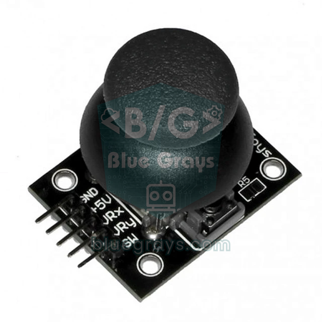
A joystick works differently from a potentiometer: it springs back to the centre when released. If you tie the angle directly to the joystick position, the joint snaps to 90 degrees the moment you let go. The right approach is speed control: the further you push the joystick, the faster the joint turns, and when you release it, the joint stays where it is. In the code below two joysticks drive four joints (left joystick for base and shoulder, right joystick for elbow and wrist); the left joystick's button opens and closes the gripper and the right one sends the arm to its home pose. Connect the left joystick's VRx and VRy outputs to A0 and A1, the right joystick's VRy and VRx outputs to A2 and A3 and the SW pins to D2 and D4; the joysticks can be powered from the Arduino's 5V pin. To compile the code, install Adafruit PWM Servo Driver Library from the Library Manager and accept the Adafruit BusIO dependency.
1#include <Wire.h>
2#include <Adafruit_PWMServoDriver.h>
3
4Adafruit_PWMServoDriver pca = Adafruit_PWMServoDriver(0x40);   // varsayılan adres / default address
5
6// Kanal: 0 taban, 1 omuz, 2 dirsek, 3 bilek, 4 bilek dönüşü, 5 kıskaç / Channel: 0 base, 1 shoulder, 2 elbow, 3 wrist, 4 wrist roll, 5 gripper
7const byte N = 6;
8const float MIN_A[N] = {0, 15, 20, 10, 0, 40};        // güvenli sınırlar / safe limits
9const float MAX_A[N] = {180, 165, 160, 170, 180, 110};
10const float HOME[N]  = {90, 90, 90, 90, 90, 40};      // başlangıç pozu, kıskaç açık / home pose, gripper open
11const byte JOY[4] = {A0, A1, A2, A3};                  // J1 X, J1 Y, J2 Y, J2 X → kanal / channel 0, 1, 2, 3
12const int8_t DIR[4] = {1, -1, 1, 1};                   // ters giden ekseni -1 yap / set -1 to invert an axis
13const byte BTN_GRIP = 2, BTN_HOME = 4;                 // joystick SW pinleri / joystick SW pins
14const float MAX_SPEED = 90;                            // en yüksek hız, derece/sn / top speed, degrees/s
15const float DT = 0.02;                                 // 20 ms döngü / 20 ms loop
16const int DEADZONE = 60;                               // ortadaki ölü bölge / dead zone around center
17
18float target[N], current[N];
19bool gripClosed = false;
20
21void writeServo(byte ch, float a) {
22  // Servo.h ile aynı 544–2400 µs aralığı / same 544–2400 µs range as Servo.h
23  pca.writeMicroseconds(ch, (uint16_t)(544 + a * (2400 - 544) / 180.0));
24}
25
26bool newPress(byte pin, byte k) {                      // her basışta bir kez true / true once per press
27  static bool prev[2] = {HIGH, HIGH};
28  bool now = digitalRead(pin);
29  bool edge = (prev[k] == HIGH && now == LOW);
30  prev[k] = now;
31  return edge;
32}
33
34void setup() {
35  pinMode(BTN_GRIP, INPUT_PULLUP);
36  pinMode(BTN_HOME, INPUT_PULLUP);
37  pca.begin();
38  pca.setOscillatorFrequency(27000000);                // çoğu modülde ~27 MHz / ~27 MHz on most boards
39  pca.setPWMFreq(50);                                  // servolar için 50 Hz / 50 Hz for servos
40  Wire.setClock(400000);                               // hızlı I2C / fast I2C
41  for (byte i = 0; i < N; i++) {
42    target[i] = current[i] = HOME[i];
43    writeServo(i, HOME[i]);
44    delay(300);                                        // servolar sırayla uyansın / wake servos one by one
45  }
46}
47
48void loop() {
49  static unsigned long last = 0;
50  if (millis() - last < 20) return;                    // 50 Hz güncelleme / 50 Hz update
51  last = millis();
52
53  // Joystick hızı belirler, konumu değil / the joystick sets speed, not position
54  for (byte i = 0; i < 4; i++) {
55    int v = analogRead(JOY[i]) - 512;
56    if (abs(v) > DEADZONE) {
57      target[i] += DIR[i] * (v / 512.0) * MAX_SPEED * DT;
58      target[i] = constrain(target[i], MIN_A[i], MAX_A[i]);
59    }
60  }
61  if (newPress(BTN_GRIP, 0)) {                         // kıskaç aç/kapa / toggle gripper
62    gripClosed = !gripClosed;
63    target[5] = gripClosed ? MAX_A[5] : MIN_A[5];
64  }
65  if (newPress(BTN_HOME, 1)) {                         // başlangıç pozuna dön / go to home pose
66    for (byte i = 0; i < N; i++) target[i] = HOME[i];
67    gripClosed = false;
68  }
69
70  // Her eklem hedefe hız sınırıyla gider / each joint follows its target with a speed limit
71  for (byte i = 0; i < N; i++) {
72    float d = constrain(target[i] - current[i], -MAX_SPEED * DT, MAX_SPEED * DT);
73    if (d != 0) {
74      current[i] += d;
75      writeServo(i, current[i]);
76    }
77  }
78}
DEADZONE stops small offsets such as 490–530 read at the centre from making the arm creep on its own. MAX_SPEED sets the speed, in degrees per second, when the joystick is pushed all the way; 90 degrees per second is a safe value to start with. If a joint moves opposite to the joystick, don't swap wires, just set the matching value in the DIR array to -1. The code keeps a target (target) and an actual position (current) for each joint; because the actual position approaches the target with a speed limit, the arm glides back smoothly even when you press the home button. Wrist roll stays fixed at 90 degrees in this sketch; you can control it with the R command in the Bluetooth section. This non-blocking timing technique is explained in detail in millis() vs delay().
Bluetooth control from your phone (HC-05)
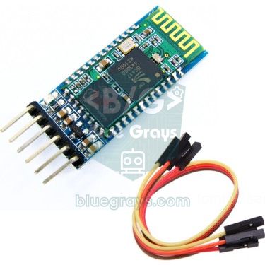
The HC-05 module creates a wireless serial link between your phone and the Arduino. Its TXD pin goes to the Arduino's D10, and its RXD pin connects to D11 through a voltage divider: D11 → 1 kΩ → RXD → 2 kΩ → GND. The divider drops the Arduino's 5 V signal to the roughly 3.3 V the HC-05 expects. The module's default data rate is 9600 baud and its pairing PIN is usually 1234. The phone sends simple text commands: a letter picks the joint, the number after it gives the angle, and a newline or semicolon ends the command.
| Command | Meaning | Example |
|---|---|---|
| B + angle | Base | B90 |
| S + angle | Shoulder | S120 |
| E + angle | Elbow | E45 |
| W + angle | Wrist (pitch) | W100 |
| R + angle | Wrist roll | R0 |
| G + angle | Gripper | G110 (close), G40 (open) |
| H | Return to home pose | H |
| K / P / X / C | Save pose / play in a loop / stop / clear poses | K |
1#include <Wire.h>
2#include <SoftwareSerial.h>
3#include <Adafruit_PWMServoDriver.h>
4
5SoftwareSerial bt(10, 11);                 // D10 ← HC-05 TXD, D11 → bölücü / divider → HC-05 RXD
6Adafruit_PWMServoDriver pca = Adafruit_PWMServoDriver(0x40);
7
8const byte N = 6;
9const char NAME[N] = {'B', 'S', 'E', 'W', 'R', 'G'};   // taban, omuz, dirsek, bilek, dönüş, kıskaç / base, shoulder, elbow, wrist, roll, gripper
10const byte MIN_A[N] = {0, 15, 20, 10, 0, 40};          // güvenli sınırlar / safe limits
11const byte MAX_A[N] = {180, 165, 160, 170, 180, 110};
12const byte HOME[N]  = {90, 90, 90, 90, 90, 40};
13const byte MAX_POSES = 30;
14const float SPEED = 1.5;                   // 20 ms'de en fazla 1,5° (75°/sn) / max 1.5° per 20 ms (75°/s)
15
16float current[N];
17byte target[N];
18byte poses[MAX_POSES][N];                  // kaydedilen pozlar (RAM) / recorded poses (RAM)
19byte poseCount = 0, playIndex = 0;
20bool playing = false;
21char buf[12];
22byte len = 0;
23
24void writeServo(byte ch, float a) {
25  pca.writeMicroseconds(ch, (uint16_t)(544 + a * (2400 - 544) / 180.0));   // 544–2400 µs
26}
27
28void handle(char *cmd) {                   // ör. / e.g. "S120", "H", "K", "P"
29  char c = toupper(cmd[0]);
30  if (c == 'H') {                          // başlangıç pozu / home pose
31    for (byte i = 0; i < N; i++) target[i] = HOME[i];
32    playing = false;
33  } else if (c == 'K') {                   // pozu kaydet / save pose
34    if (poseCount < MAX_POSES) {
35      for (byte i = 0; i < N; i++) poses[poseCount][i] = target[i];
36      poseCount++;
37    }
38    bt.print(F("Poz / pose: "));
39    bt.println(poseCount);
40  } else if (c == 'P') {                   // döngüyle oynat / play in a loop
41    if (poseCount > 0) { playing = true; playIndex = 0; }
42  } else if (c == 'X') {                   // durdur / stop
43    playing = false;
44  } else if (c == 'C') {                   // kayıtları sil / clear poses
45    poseCount = 0;
46    playing = false;
47  } else {
48    for (byte i = 0; i < N; i++) {
49      if (c == NAME[i]) {
50        target[i] = constrain(atoi(cmd + 1), MIN_A[i], MAX_A[i]);
51        playing = false;                   // elle komut oynatmayı keser / a manual command stops playback
52      }
53    }
54  }
55}
56
57bool arrived() {
58  for (byte i = 0; i < N; i++)
59    if (fabs(target[i] - current[i]) > 0.5) return false;
60  return true;
61}
62
63void setup() {
64  bt.begin(9600);                          // HC-05 varsayılan hızı / HC-05 default baud
65  pca.begin();
66  pca.setOscillatorFrequency(27000000);
67  pca.setPWMFreq(50);
68  for (byte i = 0; i < N; i++) {
69    target[i] = HOME[i];
70    current[i] = HOME[i];
71    writeServo(i, HOME[i]);
72    delay(300);                            // servolar sırayla uyansın / wake servos one by one
73  }
74}
75
76void loop() {
77  // Komutları satır satır topla / collect commands line by line
78  while (bt.available()) {
79    char ch = bt.read();
80    if (ch == '\n' || ch == '\r' || ch == ';') {
81      if (len > 0) { buf[len] = '\0'; handle(buf); len = 0; }
82    } else if (len < sizeof(buf) - 1) {
83      buf[len++] = ch;
84    }
85  }
86
87  static unsigned long last = 0, arrivedAt = 0;
88  if (millis() - last < 20) return;        // 50 Hz güncelleme / 50 Hz update
89  last = millis();
90
91  if (playing) {
92    if (!arrived()) arrivedAt = millis();  // hareket sürüyor / still moving
93    else if (millis() - arrivedAt > 300) { // her pozda 300 ms bekle / hold each pose 300 ms
94      for (byte i = 0; i < N; i++) target[i] = poses[playIndex][i];
95      playIndex = (playIndex + 1) % poseCount;   // sona gelince başa dön / wrap around
96      arrivedAt = millis();
97    }
98  }
99
100  for (byte i = 0; i < N; i++) {
101    float d = constrain(target[i] - current[i], -SPEED, SPEED);   // hız sınırı / speed limit
102    if (d != 0) {
103      current[i] += d;
104      writeServo(i, current[i]);
105    }
106  }
107}
In this sketch the servos are connected to the PCA9685 rather than directly to the Arduino, and that's deliberate. SoftwareSerial disables interrupts for about 1 ms while it receives each byte; if the servos were driven from Arduino pins with the Servo library, their pulses would stretch during that time and the arm would twitch on every command. Because the PCA9685 generates the pulses itself, the signal stays rock steady no matter how busy the Bluetooth link is. Recording and playback now happen from the phone too: move the arm to a pose with the sliders and send K; after a few poses, P makes the arm repeat them in a loop and X stops it. In this version the poses live in RAM and are lost when the board powers off; if you want them to persist, add the EEPROM method from the previous sketch.
Wireless robot arm with an ESP32
Since the ESP32 has classic Bluetooth built in, you don't need an HC-05: with the BluetoothSerial library the board appears on your phone as "BlueGrays-RobotKol" and understands the same commands. Connect the PCA9685 to GPIO 21 (SDA) and GPIO 22 (SCL) and power its VCC from 3V3; the servo signals then come out at 3.3 V, which the vast majority of servos read without trouble. BluetoothSerial only works on the classic ESP32 (ESP32-WROOM-32, DevKit); the ESP32-S2, S3 and C3 don't support classic Bluetooth.
1#include <Wire.h>
2#include <BluetoothSerial.h>
3#include <Adafruit_PWMServoDriver.h>
4
5BluetoothSerial bt;                        // klasik Bluetooth SPP / classic Bluetooth SPP
6Adafruit_PWMServoDriver pca = Adafruit_PWMServoDriver(0x40);
7
8const int N = 6;
9const char NAME[N] = {'B', 'S', 'E', 'W', 'R', 'G'};   // taban, omuz, dirsek, bilek, dönüş, kıskaç / base, shoulder, elbow, wrist, roll, gripper
10const int MIN_A[N] = {0, 15, 20, 10, 0, 40};
11const int MAX_A[N] = {180, 165, 160, 170, 180, 110};
12const int HOME[N]  = {90, 90, 90, 90, 90, 40};
13float current[N], target[N];
14String line;
15
16void writeServo(int ch, float a) {
17  pca.writeMicroseconds(ch, (uint16_t)(544 + a * (2400 - 544) / 180.0));   // 544–2400 µs
18}
19
20void handle(String cmd) {                  // ör. / e.g. "E45", "H"
21  cmd.trim();
22  if (cmd.length() == 0) return;
23  char c = toupper(cmd[0]);
24  if (c == 'H') {
25    for (int i = 0; i < N; i++) target[i] = HOME[i];
26    return;
27  }
28  int value = cmd.substring(1).toInt();
29  for (int i = 0; i < N; i++)
30    if (c == NAME[i]) target[i] = constrain(value, MIN_A[i], MAX_A[i]);
31}
32
33void setup() {
34  Serial.begin(115200);
35  bt.begin("BlueGrays-RobotKol");          // telefonda görünen ad / name shown on the phone
36  Wire.begin(21, 22);                      // SDA = GPIO 21, SCL = GPIO 22
37  pca.begin();
38  pca.setOscillatorFrequency(27000000);
39  pca.setPWMFreq(50);
40  for (int i = 0; i < N; i++) {
41    current[i] = target[i] = HOME[i];
42    writeServo(i, HOME[i]);
43    delay(300);
44  }
45  Serial.println("Bluetooth hazir / ready");
46}
47
48void loop() {
49  while (bt.available()) {
50    char ch = bt.read();
51    if (ch == '\n' || ch == ';') { handle(line); line = ""; }
52    else if (line.length() < 12) line += ch;
53  }
54
55  static unsigned long last = 0;
56  if (millis() - last < 20) return;        // 50 Hz güncelleme / 50 Hz update
57  last = millis();
58  for (int i = 0; i < N; i++) {
59    float d = constrain(target[i] - current[i], -1.5f, 1.5f);   // yumuşak hareket / smooth motion
60    if (d != 0) {
61      current[i] += d;
62      writeServo(i, current[i]);
63    }
64  }
65}
Robot arm with a Raspberry Pi Pico (MicroPython)
You don't need any extra library to drive servos on the Raspberry Pi Pico: set the PWM to 50 Hz and give the pulse width in nanoseconds with duty_ns(). With 16 PWM channels, the Pico can drive 6 servos directly; pin pairs sharing the same slice share a frequency, but since every servo uses 50 Hz that's not a problem. The limitation is on the analog side: the Pico has only three usable ADC pins (GP26, GP27, GP28). That's why in the code below three joints are driven by pots and the gripper opens and closes with a button on GP14. Since the Pico runs at 3.3 V, connect the pots to 3V3; power the servos from an external 5 V supply as before.
1from machine import Pin, PWM, ADC
2import time
3
4# Servo pinleri: taban, omuz, dirsek, kıskaç / servo pins: base, shoulder, elbow, gripper
5servos = [PWM(Pin(p)) for p in (10, 11, 12, 13)]
6for s in servos:
7    s.freq(50)                                  # 50 Hz servo sinyali / 50 Hz servo signal
8
9pots = [ADC(26), ADC(27), ADC(28)]              # Pico'da 3 ADC pini var / the Pico has 3 ADC pins
10button = Pin(14, Pin.IN, Pin.PULL_UP)           # kıskaç butonu GND'ye / gripper button to GND
11
12MIN_A = (0, 15, 20, 40)                         # güvenli sınırlar / safe limits
13MAX_A = (180, 165, 160, 110)
14
15def write(i, angle):
16    angle = max(MIN_A[i], min(MAX_A[i], angle))
17    servos[i].duty_ns(544000 + int(angle * 10311))   # 544–2400 µs aralığı / 544–2400 µs range
18
19smooth = [p.read_u16() for p in pots]
20grip_closed = False
21last_btn = 1
22write(3, MIN_A[3])                              # kıskaç açık başlar / gripper starts open
23
24while True:
25    for i in range(3):
26        smooth[i] += (pots[i].read_u16() - smooth[i]) * 0.2   # yumuşatma / smoothing
27        write(i, MIN_A[i] + (MAX_A[i] - MIN_A[i]) * smooth[i] / 65535)
28    b = button.value()
29    if b == 0 and last_btn == 1:                # yeni basış / new press
30        grip_closed = not grip_closed
31        write(3, MAX_A[3] if grip_closed else MIN_A[3])
32    last_btn = b
33    time.sleep_ms(20)                           # 50 Hz döngü / 50 Hz loop
Going further: inverse kinematics
So far we've set each joint's angle one by one; that's called forward kinematics. Inverse kinematics does the opposite: you give the point (x, y) you want the gripper to reach and the code calculates the joint angles needed. For a two-link arm with shoulder–elbow length L1 and elbow–wrist length L2, first compute D = (x² + y² − L1² − L2²) / (2·L1·L2). The elbow angle is θ2 = acos(D) and the shoulder angle is θ1 = atan2(y, x) + atan2(L2·sin θ2, L1 + L2·cos θ2) (the elbow-up solution). For example, with L1 = L2 = 12 cm and a point 15 cm in front of and 5 cm above the shoulder, you get D ≈ −0.13, θ2 ≈ 97.6° and θ1 ≈ 67.2°: the upper arm points 67 degrees above horizontal and the forearm bends down 97.6 degrees relative to it. If the absolute value of D is greater than 1, the point is out of the arm's reach. The base angle is calculated separately from the target's position seen from above. When converting the results to servo angles, account for each servo's mounting direction and centre point.
Jitter and resets: common mistakes and fixes
| Symptom | Likely cause | Fix |
|---|---|---|
| Servos jitter and buzz while the arm is still | Noise in the pot readings or a weak supply | Add a smoothing filter and a 2° deadband, use an external supply and a 1000 µF capacitor |
| The Arduino resets when the arm moves, the HC-05 drops its connection | The servos' start-up current pulls the voltage down | Power the servos from a separate 5–6 V supply, join the grounds, start the servos one by one at power-up |
| Servos twitch whenever a Bluetooth command arrives | SoftwareSerial interrupts disturb the Servo library's pulses | Move the servos to a PCA9685 or use the ESP32's built-in Bluetooth |
| The arm lunges somewhere at power-up | Servos don't remember their last position and move at full speed on the first command | Park the arm in its home pose before switching off, call write() before attach() |
| The shoulder can't lift the arm or slowly sags | Not enough torque | Do the torque calculation; use an MG996R, a shorter arm, a counterweight or a spring |
| A joint stalls at one end and gets hot | The servo is pushing against a mechanical stop | Put the MIN_A and MAX_A limits from calibration into the code |
| The gripper servo heats up while holding an object | The gripper keeps trying to close and the servo stays stalled | Set the closed angle to the point where it just touches the object, add rubber to the fingers |
| The PCA9685 is connected but no servo moves | No power on the V+ terminal or no common ground | Supply 5–6 V to V+ and check the I2C address (0x40) |
| A joint slips under load | A plastic horn has stripped or the centre screw is missing | Use a metal horn and fix it to the shaft with the centre screw |
Robot arm project ideas
- Colour-sorting arm: Read the colour of cubes with a TCS3200 colour sensor and let the arm drop each colour into its own box.
- Gesture control: With an MPU6050 on a glove, the robot arm tilts the same way as your wrist.
- Wireless remote: Connect two joysticks to a separate Arduino and send the commands with an nRF24L01; you get a remote control that doesn't need a phone.
- Browser control: Create sliders on a web page with an ESP32 and control the arm from any device on the same Wi-Fi network; an ESP32 WebSocket keeps the latency to a minimum.
- Pick from a conveyor: Build a small conveyor belt with a stepper motor; when a TCRT5000 spots an object, the arm picks it off the belt.
- Competition and school project: A record-and-playback arm is a strong choice among science fair project ideas, showing mechanics, electronics and software together.
An Arduino robotic arm is a project that teaches mechanical design, torque calculation, power management and smooth-motion coding all at once, and it grows the more effort you put in. Start with a 4-servo arm controlled by potentiometers, add record and playback, then move up to 6 servos with a PCA9685 and Bluetooth. In the BlueGrays app you'll find projects such as servo control with a potentiometer and a joystick, Bluetooth control from your phone and a 32-servo choreography, complete with circuit diagrams and step-by-step code, so you can try every joint of your arm on its own first.
Frequently asked questions
Which servo motor should I use for an Arduino robotic arm?
For load-bearing joints such as the base, shoulder and elbow, the metal-gear MG996R with 9–11 kg·cm of torque is a good choice. For light joints such as the wrist and gripper, an MG90S or SG90 is enough. Small arms built only with SG90s work if they're kept short and light, but they can only lift objects of a few tens of grams.
What power supply does a robot arm need?
A 5 V 3 A adapter is enough for a small arm with 4 SG90 or MG90S servos. For a 6-servo arm with 3 MG996Rs and 3 small servos, use a 5–6 V switching adapter rated at least 5 A, or 10 A for comfortable headroom. Don't forget to connect the adapter's negative to the Arduino's GND.
How many servos can an Arduino control?
The Servo library can drive up to 12 servos on an Arduino Uno and 48 on a Mega. The real limit is current, though: all servos should be powered from an external supply. A PCA9685 module drives 16 servos using only two I2C pins and can be chained up to 62 modules.
Why are my robot arm servos jittering?
The most common causes are a weak power supply, a missing common ground and noise in the potentiometer readings. Use an external supply with a 1000 µF capacitor on the servo rail, and add a smoothing filter and a deadband in the code. If SoftwareSerial and the Servo library are used together, moving the servos to a PCA9685 removes the jitter completely.
How much weight can an SG90 robot arm lift?
The SG90's stall torque is about 1.8 kg·cm; for safe operation, budget half of that, 0.9 kg·cm. Since the arm and servos use up part of that budget with their own weight, an SG90 arm around 15 cm long can in practice carry only light objects of 20–30 g, such as a bottle cap or a small foam cube.
How do I control a robot arm from my phone?
Connect an HC-05 Bluetooth module to the Arduino and use a Bluetooth serial terminal or a slider controller app on your phone to send text commands such as "S120". With an ESP32, the built-in Bluetooth means you don't need an extra module. The HC-05 doesn't work with iPhones, so for an iPhone you need a BLE module or ESP32 BLE.
Projects to build after reading this
See all projects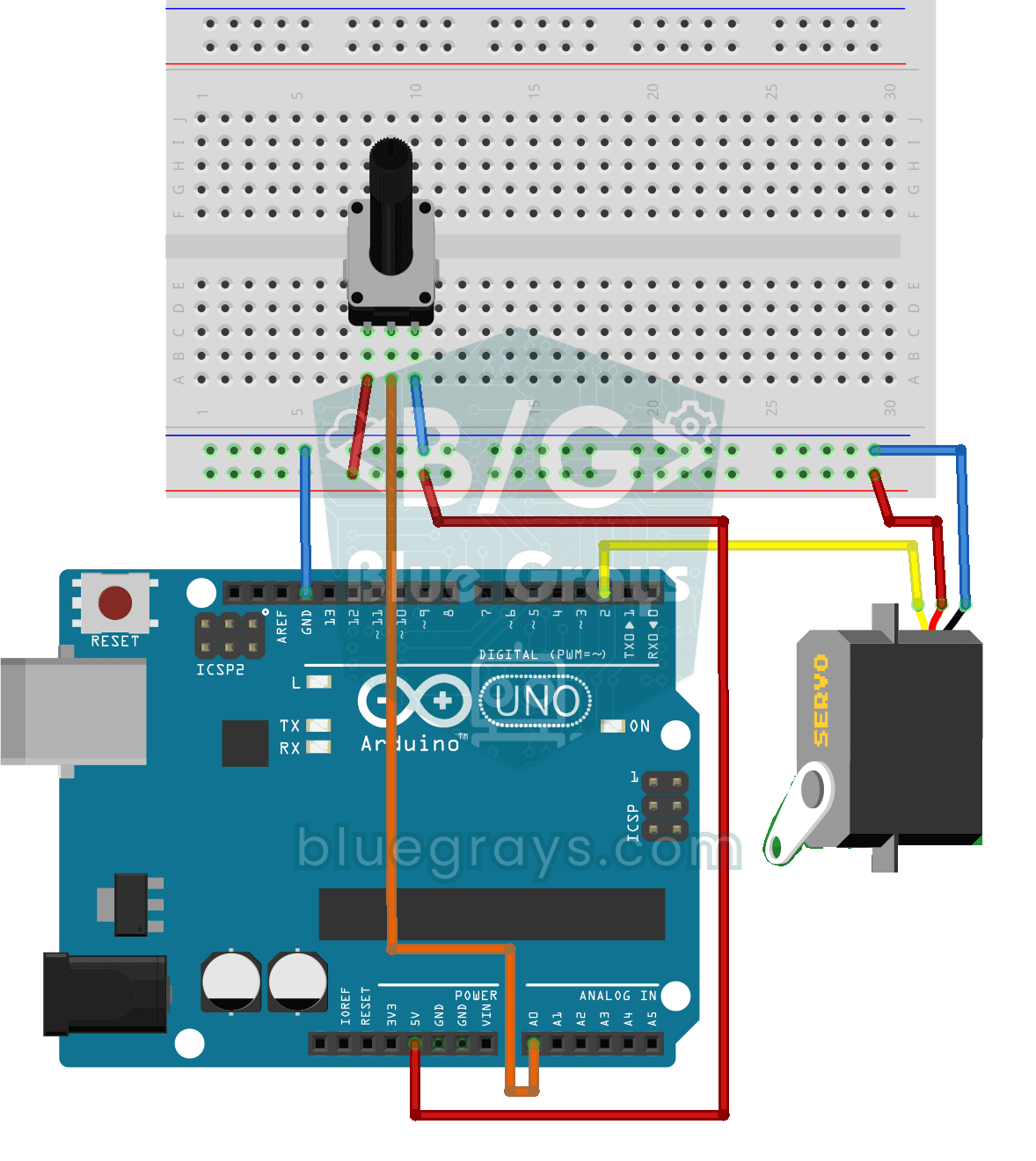
Servo Motor Operation with Potentiometer
As you turn the potentiometer knob, the servo motor's arm turns right along with it: one end of the knob means zero degrees, the other end means half a turn. The Arduino keeps reading the knob's posit
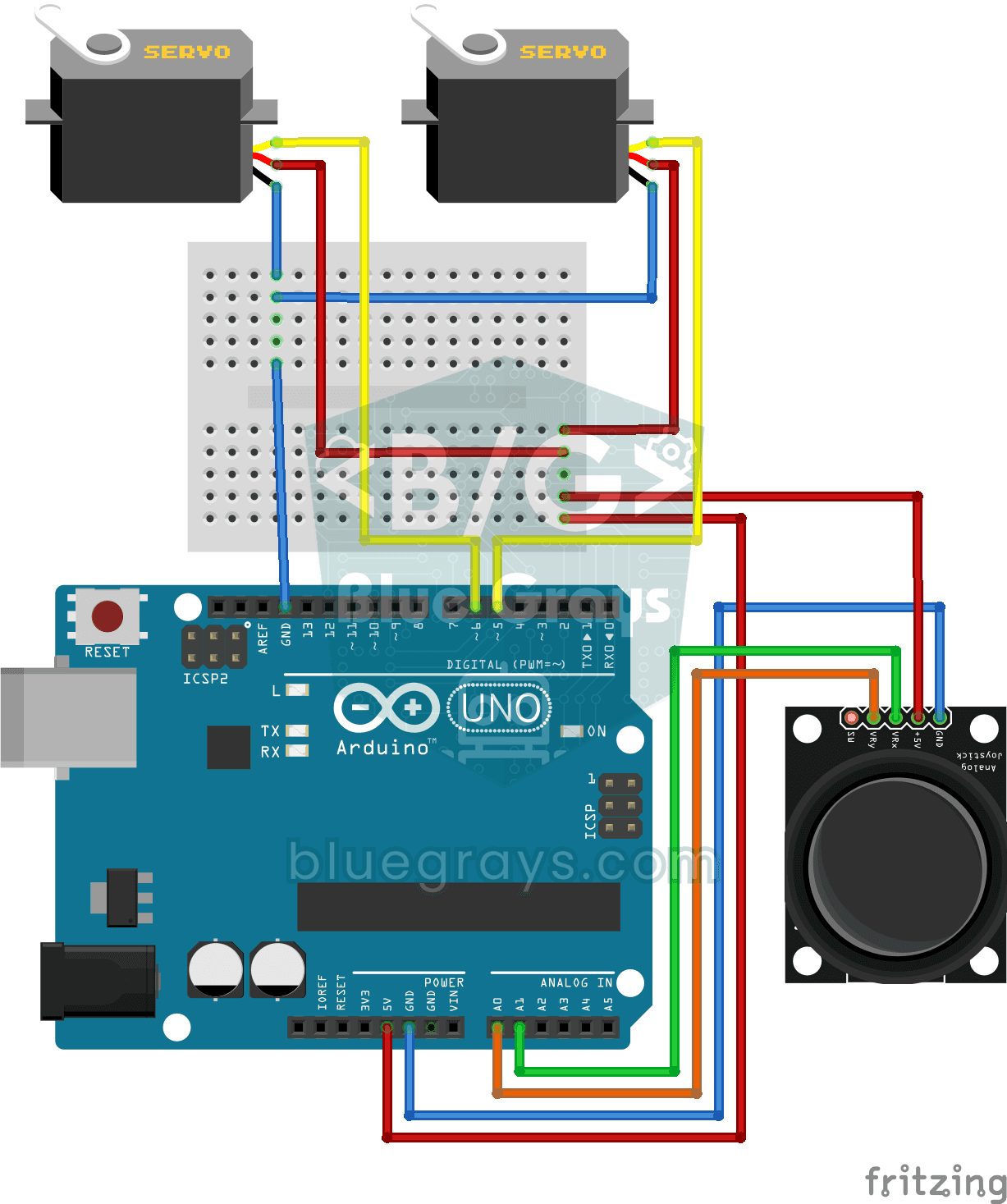
Servo Control with Joystick
Steer two motors with a joystick, just like turning a security camera. Push the stick left or right and the bottom servo motor slowly turns, push it up or down and the top servo tilts up and down; let
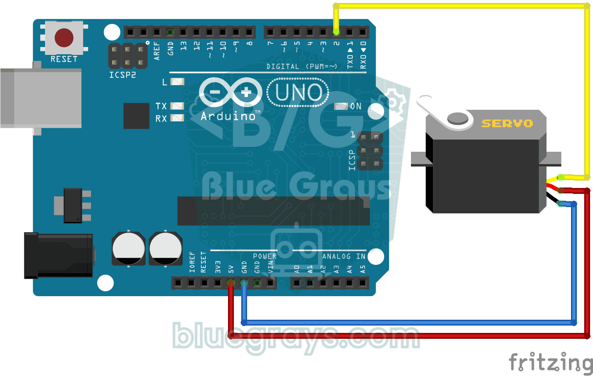
Using a Servo Motor
The arm of a small servo motor turns to three positions in turn: all the way to the start, right to the middle and all the way to the end, waiting two seconds at each stop. The Arduino tells the motor

ESP32 Servo Motor (Potentiometer Control)
In this project, we control an SG90 servo motor using a potentiometer. We adjust the servo angle by mapping the analog value read from the potentiometer to the 0–180-degree range. The ESP32Servo library generates servo signals on suitable output-capable GPIO pins of the ESP32; this project uses GPIO 18. This is a fundamental control method for robotic arms, camera gimbals, and automatic door mechanisms.
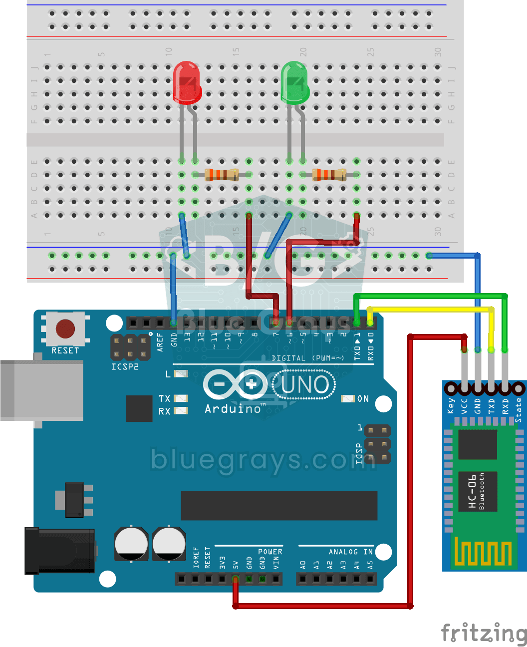
Control an LED from Your Phone via Bluetooth
A small rehearsal for switching the lights in your room on and off from your phone. The Bluetooth module passes the letters sent from your phone to the Arduino; one letter turns on the red LED, anothe

Bluetooth Controlled Car with L298N
Turn your phone into a remote and drive your own robot car. The Arduino receives commands from a remote-control app on your phone through a Bluetooth module and spins the wheels with a motor driver; t

Servo Circle Choreography - Animated Patterns with 32 Servos
A visual animation project using 32 servo motors arranged in a circle on an Arduino Mega. The servos are managed in a single array, connected to Mega's pins 22-53, and exhibit four different motion sequences: a chaotic vibration where all servos move at random angles, a synchronous sweep where they all move at the same time, a smoothly rotating wave around a circle, and finally a compass needle swinging left and right. The swirling wave effect is created by the rotation of each servo relative to