
MG996R Servo with Arduino: Torque, Current, Power Supply and Code
How to use the MG996R servo: 11 kg·cm torque and 2.5 A stall current, external 5–6 V supply, capacitor, 500–2500 µs range, fixing jitter, PCA9685 and SG90.
The MG996R servo is the go-to servo for heavy jobs in Arduino projects, thanks to its metal gears and up to 11 kg·cm of torque at 6 V. With a 55-gram body it can lift the shoulder of a robotic arm, open a heavy lid or swing a pan-tilt camera mount. That strength comes at a price, though: when it's loaded, the MG996R draws up to 2.5 A. So unlike an SG90, you can't just plug it into the Arduino's 5V pin; it needs an external 5–6 V supply, a common GND and a capacitor close to the servo. Ignore these rules and the servo jitters, the Arduino keeps resetting, and your computer may even shut down the USB port.
In this guide you'll learn to interpret the MG996R's torque and current figures with real numbers, choose the right power supply, use the 500–2500 µs range with the Servo library to find your own servo's limits, and prevent jitter and resets. Then we'll move on to ESP32 and Raspberry Pi Pico code, the PCA9685 module that drives 16 servos over two wires, choosing servos for a robotic arm, and a comparison with the SG90 and MG90S.
What is the MG996R servo and how does it work?
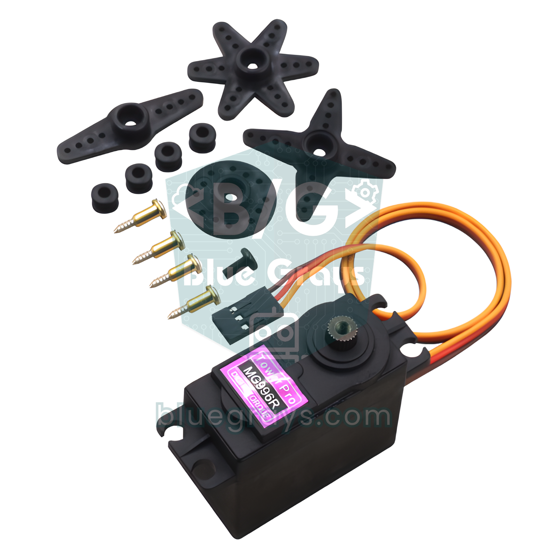
The MG996R is an upgraded version of TowerPro's older MG995: its redesigned control board and gears centre more reliably and leave less play. Inside the case there's a small DC motor, a metal gearbox that slows the motor down and multiplies its torque, a potentiometer that measures the angle of the output shaft, and a control board that manages them all. The board reads the width of the pulse arriving on the signal wire every 20 ms (50 Hz), compares the requested angle with the angle the potentiometer reports, and turns the motor until the difference disappears. A pulse of about 1500 µs means the centre position; shorter pulses turn the shaft one way, longer ones the other way. The 5 µs dead band in the datasheet means the servo ignores changes smaller than that. We explained how servo motors work in general in What Is a Servo Motor?.
| Feature | Value |
|---|---|
| Operating voltage | 4.8–7.2 V (5–6 V in practice) |
| Stall torque | 9.4 kg·cm (4.8 V), 11 kg·cm (6 V) ≈ 0.92–1.08 N·m |
| Speed (per 60°) | 0.17 s (4.8 V), 0.14 s (6 V) |
| Idle current | About 10 mA (no load, shaft at rest) |
| Running current | 500–900 mA (6 V, while moving) |
| Stall current | 2.5 A (6 V) |
| Dead band | 5 µs |
| Rotation | About 120° with 1000–2000 µs, close to 180° with 500–2500 µs (varies from unit to unit) |
| Signal | 50 Hz (20 ms period), position set by pulse width |
| Gears and bearing | Metal gears, dual ball bearing |
| Output shaft | 25 teeth (25T spline) |
| Weight and size | 55 g, 40.7 × 19.7 × 42.9 mm |
| Cable | About 30 cm; brown GND, red positive, orange signal |
| Operating temperature | 0–55 °C |
What does torque mean? Reading the kg·cm rating correctly
Torque is the servo's ability to turn a load at a certain distance from its shaft, and it's measured as force × distance. 11 kg·cm means it can hold 11 kg at 1 cm from the shaft, or 1.1 kg at 10 cm; double the distance and the load it can carry is halved. To convert to newton metres, multiply by 0.098: 11 kg·cm ≈ 1.08 N·m. Here's the key detail: the datasheet value is the stall torque, the limit at which the shaft stops, the current peaks and the servo heats up. For continuous use, staying at no more than half of that value keeps the servo cool, reduces jitter and makes the gears last longer.
| Arm length (shaft to load) | Stall limit (6 V) | Safe continuous load (50%) |
|---|---|---|
| 2.5 cm (end of the horn) | 4.4 kg | 2.2 kg |
| 5 cm | 2.2 kg | 1.1 kg |
| 10 cm | 1.1 kg | 550 g |
| 15 cm | About 730 g | About 365 g |
| 20 cm | 550 g | 275 g |
The table only accounts for the load at the tip. In a real mechanism, the weight of the arm itself, the other servos mounted on it and the gripper all add to the torque; you have to multiply each part's mass by its distance from the shaft and add them up. For example, if a 15 cm arm carries a 150 g gripper and a 100 g object at its end, those two alone come to 0.25 × 15 = 3.75 kg·cm; with the arm's own weight the total can reach 5 kg·cm. That's just under half of the MG996R's stall torque at 6 V, so it's the right choice. You'll find a part-by-part torque calculation with an example in the Arduino robotic arm guide.
Current: why can't the MG996R run from the Arduino's 5V pin?
At rest with no load the MG996R draws only about 10 mA (holding a load raises this with the load), but while moving the current rises to 0.5–0.9 A, and when the shaft is loaded and during the first milliseconds of every start it approaches 2.5 A. When an Arduino Uno runs from USB, the total current you can take from its 5V pin is limited by the board's 500 mA fuse, and the board itself uses part of that. The moment the servo starts, the 5 V rail sags noticeably for a few milliseconds, the processor becomes unstable and the board restarts. The computer may also shut down a USB port that sees too much current for a while.
The wires are part of the problem too. The thin jumper wires and breadboard contacts used on a breadboard easily add up to 0.2 Ω. Work it out with Ohm's law: at a 2.5 A peak, 2.5 × 0.2 = 0.5 V is lost in the wiring alone, so a 5 V supply reaches the servo as 4.5 V, and the servo gets weaker and jitters. Breadboard contacts are also designed for about 1 A. Connect the MG996R's power wires straight to a screw terminal or a soldered distribution rail instead of the breadboard, and use 20–22 AWG wire.
| Number of servos | While moving | Worst case (all stalled) | Recommended supply |
|---|---|---|---|
| 1 MG996R | 0.5–0.9 A | 2.5 A | 5–6 V, at least 3 A |
| 2 servos | 1–1.8 A | 5 A | 5–6 V, 5 A |
| 4 servos | 2–3.6 A | 10 A | 5–6 V, 6–10 A switching adapter |
| 6 servos (robotic arm) | 3–5.4 A | 15 A | 6 V, 10 A plus code that moves the servos in turn |
| 16 servos (PCA9685) | 8–14 A | 40 A | Several separate 6 V rails or a 20 A+ supply |
Powering it right: external 5–6 V, common GND and a capacitor
- Choose the supply: Use a 5 V or 6 V switching adapter that can deliver the current in the table above for your number of servos. For portable projects, 4 AA NiMH cells (4.8 V) or a 2S LiPo with a step-down regulator (UBEC) set to 6 V work well.
- Feed the positive only to the servo: Connect the supply's positive to the MG996R's red wire; don't connect it to the Arduino's 5V pin.
- Join the grounds: Connect the supply's negative to both the servo's brown wire and the Arduino's GND pin. The signal is a voltage measured relative to GND, so without a common GND the servo can't understand the pulses.
- Connect the signal: Connect the orange wire to pin D9 on the Arduino Uno (GPIO 18 on the ESP32, GP15 on the Pico).
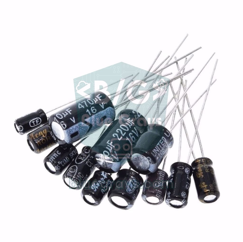
- Add a capacitor: Place a 470–1000 µF / 16 V electrolytic capacitor across the servo's power leads, as close to the servo as possible; the leg marked with the stripe goes to negative. With several servos, allow about 100 µF per servo.
- Power the Arduino separately: Run the board from USB or the DC jack. That way, the voltage dips caused by the servo don't reach the processor.
| Connection | Arduino Uno | ESP32 | Raspberry Pi Pico |
|---|---|---|---|
| Orange wire (signal) | D9 | GPIO 18 | GP15 |
| Red wire (positive) | External 5–6 V positive | External 5–6 V positive | External 5–6 V positive |
| Brown wire (GND) | Supply negative + Arduino GND | Supply negative + ESP32 GND | Supply negative + Pico GND |
| Capacitor (470–1000 µF) | Across the servo's positive and negative | Across the servo's positive and negative | Across the servo's positive and negative |
| Potentiometer (ESP32 example) | — | Wiper to GPIO 34, outer legs to 3V3 and GND | — |
The Servo library and the 500–2500 µs range
Arduino's Servo library comes with the IDE. When you write servo.attach(9), the library uses a default range of 544–2400 µs and maps write(0) and write(180) to those two ends; many MG996Rs fall a little short of 180 degrees in this range. To widen it, write servo.attach(9, 500, 2500). This detail matters because writeMicroseconds() can't go beyond the limits given to attach either: if you write writeMicroseconds(2500) without setting the limits, the library silently clamps it to 2400. Also, write() treats numbers below 544 as an angle and larger numbers as microseconds.
On the Arduino Uno, the Servo library supports up to 12 servos, and because it uses Timer1, analogWrite doesn't work on pins 9 and 10 while a servo is attached. Each MG996R's mechanical limit is also slightly different: the manufacturer's datasheet gives about 120 degrees of rotation with standard 1000–2000 µs pulses, while with the wider range most servos get close to 180 degrees. A servo pushed past its limit runs into its internal end stop, draws stall current, buzzes and heats up. So the first job is to find your own servo's safe pulse range with the sketch below.
1#include <Servo.h>
2
3const byte SERVO_PIN = 9;          // turuncu sinyal kablosu / orange signal wire
4Servo servo;
5int pulseUs = 1500;                // orta konum / center position
6
7void setup() {
8  Serial.begin(115200);
9  servo.writeMicroseconds(pulseUs);      // önce darbe, sonra attach / pulse first, then attach
10  servo.attach(SERVO_PIN, 500, 2500);    // aralığı genişlet / widen the range
11  Serial.println(F("500-2500 arasi bir deger yaz / type a value between 500 and 2500"));
12}
13
14void loop() {
15  if (Serial.available()) {
16    long value = Serial.parseInt();             // yazılan sayıyı oku / read the typed number
17    while (Serial.available()) Serial.read();   // satır sonunu temizle / clear the line ending
18    if (value >= 500 && value <= 2500) {
19      int step = (value > pulseUs) ? 10 : -10;  // 10 µs adımlarla yavaşça git / move slowly in 10 µs steps
20      while (abs(value - pulseUs) >= 10) {
21        pulseUs += step;
22        servo.writeMicroseconds(pulseUs);
23        delay(5);
24      }
25      pulseUs = value;
26      servo.writeMicroseconds(pulseUs);
27      Serial.print(F("Darbe / pulse: "));
28      Serial.print(pulseUs);
29      Serial.println(F(" us"));
30    }
31  }
32}- Upload the sketch, open the Serial Monitor at 115200 baud and set the line ending to New Line.
- Type 1500; the servo moves to the centre. Fit the horn at this moment so that it points to the centre position of your mechanism.
- Work towards the lower limit in 50 µs steps with values like 1000, 800 and 700. If the servo no longer moves or starts buzzing, go back 30–50 µs from the last value and note that number as MIN_US.
- Do the same for the upper limit with values like 2000, 2200 and 2300 to find MAX_US. You'll use these two numbers in the next sketches.
Smooth motion: code that reduces current surges and jerks
A single command like servo.write(160) throws the servo to its target at full speed, covering 60 degrees in 0.14 seconds at 6 V. Meanwhile the motor draws close to its stall current, the mechanism jerks and the object being held can fall. Splitting the movement into small steps reduces both the current peaks and the mechanical shock. The sketch below advances the servo 1 degree every 15 ms (about 67°/s), and because it uses millis(), you can do other things at the same time.
1#include <Servo.h>
2
3const byte SERVO_PIN = 9;
4const int MIN_US = 550;            // kalibrasyonda bulduğun alt sınır / lower limit from calibration
5const int MAX_US = 2450;           // kalibrasyonda bulduğun üst sınır / upper limit from calibration
6const byte STEP_MS = 15;           // derece başına süre: 15 ms ≈ 67°/sn / time per degree: 15 ms ≈ 67°/s
7
8const int POSES[] = {20, 160, 90, 45, 135};    // sırayla gidilecek açılar / angles to visit in order
9const byte POSE_COUNT = sizeof(POSES) / sizeof(POSES[0]);
10
11Servo servo;
12int current = 90;                  // şu anki açı / current angle
13int target = 90;                   // hedef açı / target angle
14byte poseIndex = 0;
15unsigned long lastStep = 0;
16unsigned long arrivedAt = 0;
17
18int angleToUs(int angle) {
19  return map(angle, 0, 180, MIN_US, MAX_US);   // açıyı darbeye çevir / angle to pulse width
20}
21
22void setup() {
23  servo.writeMicroseconds(angleToUs(current)); // önce konum, sonra attach / position first, then attach
24  servo.attach(SERVO_PIN, MIN_US, MAX_US);
25  arrivedAt = millis();
26}
27
28void loop() {
29  unsigned long now = millis();
30
31  // Hedefe 1 derecelik adımlarla yaklaş / approach the target in 1-degree steps
32  if (current != target && now - lastStep >= STEP_MS) {
33    lastStep = now;
34    current += (target > current) ? 1 : -1;
35    servo.writeMicroseconds(angleToUs(current));
36    if (current == target) arrivedAt = now;
37  }
38
39  // Hedefte 1 sn bekle, sonra sıradaki poza geç / wait 1 s at the target, then take the next pose
40  if (current == target && now - arrivedAt >= 1000) {
41    target = POSES[poseIndex];
42    poseIndex = (poseIndex + 1) % POSE_COUNT;
43  }
44
45  // Burada başka işler de yapılabilir / other tasks can run here too
46}
The angleToUs() function maps the angle between the MIN_US and MAX_US values you found during calibration, so 0 and 180 degrees become the servo's real, safe end points. A servo doesn't remember its position while powered off, and it moves to the commanded angle at full speed as soon as it receives the first pulse. Calling writeMicroseconds() before attach() makes the library skip its default 1500 µs pulse and send your starting angle straight away; if you bring the mechanism back to the same starting pose before switching off, the jump at power-up almost disappears. Set the speed with STEP_MS: 30 ms gives a slow, smooth movement, 5 ms a fast but jerky one. If you want to drive the servo with a potentiometer, just convert the reading to an angle and write it to the target variable.
Jitter and Arduino resets: causes and fixes
| Symptom | Likely cause | Fix |
|---|---|---|
| The Arduino resets and the USB connection drops when the servo moves | The servo is powered from the Arduino's 5V pin and its start-up current pulls the voltage down | External 5–6 V supply, common GND and a 470–1000 µF capacitor |
| The servo jitters or buzzes while standing still | Weak supply, thin wires or a load close to the stall torque | Use thick wires and a capacitor, shorten the arm or reduce the load |
| It keeps twitching when controlled with a potentiometer | Noise of a few counts in the analog reading | Add a smoothing filter and a 2-degree dead band |
| The servo moves randomly or doesn't respond at all | The external supply's GND isn't connected to the Arduino | Connect the supply's negative to the Arduino's GND pin |
| It buzzes and heats up at the ends | The pulse range exceeds the servo's mechanical limit | Narrow MIN_US and MAX_US through calibration |
| It twitches when used with NeoPixel, SoftwareSerial or IR libraries | These libraries briefly disable interrupts, so the pulse length drifts | Move the servo to a PCA9685 or use a board with hardware PWM |
| The ESP32 prints "Brownout detector was triggered" and restarts | The servo and the ESP32 share the same weak supply | Power the servo from a separate supply and join the grounds |
| Clicking and slipping under load | A gear tooth is broken or the plastic horn is stripped | Replace the gear set, use a metal 25T horn and the centre screw |
| Torque far below the rated value | A poor-quality copy or a low supply voltage | Try 6 V, buy from a reliable seller and keep a 50% margin |
Controlling the MG996R with an ESP32
The standard Arduino Servo library doesn't work on the ESP32; install the ESP32Servo library from the Library Manager. It's used almost the same way: you set the period with setPeriodHertz(50), and the library doesn't accept limits outside 500–2500 µs. The ESP32's signal output is 3.3 V, and the vast majority of MG996Rs read it without trouble; if your servo doesn't respond or behaves erratically, add a logic level converter to the signal line. In the example below, a potentiometer connected to GPIO 34 turns the servo. Because the ESP32's ADC is 12-bit, readings range from 0 to 4095 and are a little noisy, which is why the code uses filtering and a dead band.
1#include <ESP32Servo.h>
2
3const int SERVO_PIN = 18;          // servo sinyali / servo signal
4const int POT_PIN = 34;            // pot orta bacağı (ADC1) / pot wiper (ADC1)
5const int MIN_US = 500;            // ESP32Servo bu aralığın dışına çıkmaz / ESP32Servo stays within 500–2500
6const int MAX_US = 2500;
7
8Servo servo;
9float smooth = 0;                  // süzülmüş pot değeri / filtered pot value
10int lastAngle = -1;
11
12void setup() {
13  Serial.begin(115200);
14  ESP32PWM::allocateTimer(0);              // servo için zamanlayıcı ayır / reserve a timer for the servo
15  servo.setPeriodHertz(50);                // 50 Hz = 20 ms periyot / 20 ms period
16  servo.attach(SERVO_PIN, MIN_US, MAX_US);
17  smooth = analogRead(POT_PIN);
18}
19
20void loop() {
21  smooth += (analogRead(POT_PIN) - smooth) * 0.1;   // ADC gürültüsünü süz / filter ADC noise
22  int angle = map((int)smooth, 0, 4095, 0, 180);    // 12 bit ADC: 0–4095
23  if (abs(angle - lastAngle) >= 2) {                // ölü bant: titremeyi keser / deadband stops jitter
24    servo.write(angle);
25    lastAngle = angle;
26    Serial.println(angle);
27  }
28  delay(20);
29}
MG996R with the Raspberry Pi Pico (MicroPython)
On the Raspberry Pi Pico you don't need an extra library: set the PWM to 50 Hz and give the pulse width in nanoseconds with duty_ns(); 500 µs means 500000 ns. The Pico's signal is 3.3 V as well. Don't power the servo from the Pico's VBUS or VSYS pin; the current on these pins comes from the computer's USB port, and the MG996R's peak current will restart the Pico. Power the servo from an external supply and join the grounds. The code below moves the servo smoothly, degree by degree, between three positions.
1from machine import Pin, PWM
2import time
3
4MIN_NS = 500000                   # 500 µs = 0 derece / 0 degrees
5MAX_NS = 2500000                  # 2500 µs = 180 derece / 180 degrees
6
7servo = PWM(Pin(15))              # turuncu kablo GP15'e / orange wire to GP15
8servo.freq(50)                    # 50 Hz servo sinyali / 50 Hz servo signal
9
10def write_angle(angle):
11    angle = max(0, min(180, angle))                           # 0–180 ile sınırla / clamp to 0–180
12    servo.duty_ns(MIN_NS + (MAX_NS - MIN_NS) * angle // 180)  # açıyı darbeye çevir / angle to pulse
13
14def move_slow(start, end, ms_per_degree=15):
15    step = 1 if end > start else -1
16    for a in range(start, end + step, step):  # 1 derecelik adımlar / 1-degree steps
17        write_angle(a)
18        time.sleep_ms(ms_per_degree)
19
20write_angle(90)                   # ortadan başla / start at the center
21time.sleep(1)
22
23while True:
24    move_slow(90, 170)
25    time.sleep(1)
26    move_slow(170, 10)
27    time.sleep(1)
28    move_slow(10, 90)
29    time.sleep(1)
16 servos with a PCA9685: lots of MG996Rs over two wires
When the number of servos grows, or when you work with libraries that disable interrupts, the PCA9685 module makes life easier. This board is a 16-channel, 12-bit PWM generator that talks to the Arduino over I2C using only the SDA and SCL wires. Because it generates the pulses with its own clock, the signal stays steady even while the processor is busy with other work. Its default address is 0x40; by changing the address with the A0–A5 solder jumpers on the board, you can connect 62 boards to the same bus, which means 992 servos in theory. At 50 Hz, the 20 ms period is divided into 4096 steps, and one step is about 4.9 µs: 500 µs is about 102 steps and 2500 µs about 512.
| PCA9685 pin | Arduino Uno | ESP32 | Raspberry Pi Pico |
|---|---|---|---|
| GND | GND | GND | GND |
| VCC (chip power only) | 5V | 3V3 | 3V3 |
| SDA | A4 | GPIO 21 | GP4 |
| SCL | A5 | GPIO 22 | GP5 |
| V+ terminal (servo power) | External 5–6 V | External 5–6 V | External 5–6 V |
| OE | Leave unconnected | Leave unconnected | Leave unconnected |
1#include <Wire.h>
2#include <Adafruit_PWMServoDriver.h>
3
4Adafruit_PWMServoDriver pca = Adafruit_PWMServoDriver(0x40);   // varsayılan adres / default address
5
6const byte SERVO_COUNT = 16;
7const uint16_t MIN_US = 500;       // kalibrasyonla daralt / narrow it after calibration
8const uint16_t MAX_US = 2500;
9
10uint16_t angleToUs(float angle) {
11  return MIN_US + (uint16_t)(angle * (MAX_US - MIN_US) / 180.0);
12}
13
14void setup() {
15  pca.begin();
16  pca.setOscillatorFrequency(27000000);   // kartın gerçek saatine yakın / close to the real board clock
17  pca.setPWMFreq(50);                     // servolar için 50 Hz / 50 Hz for servos
18  delay(10);
19  for (byte ch = 0; ch < SERVO_COUNT; ch++) {
20    pca.writeMicroseconds(ch, angleToUs(90));   // hepsini ortala / center them all
21    delay(200);                                 // sırayla başlat: akım darbesini dağıt / one by one: spread the current surge
22  }
23}
24
25void loop() {
26  // Dalga: her servo komşusundan biraz geride / wave: each servo slightly behind its neighbour
27  float t = millis() / 1000.0;
28  for (byte ch = 0; ch < SERVO_COUNT; ch++) {
29    float angle = 90 + 40 * sin(t * 2.0 - ch * 0.4);   // 50–130° arası / between 50° and 130°
30    pca.writeMicroseconds(ch, angleToUs(angle));
31  }
32  delay(20);
33}
To run the sketch, install the Adafruit PWM Servo Driver library from the Library Manager. The setOscillatorFrequency(27000000) line matters: on paper the PCA9685's internal clock is 25 MHz, but in reality it varies between about 23 and 27 MHz, and Adafruit's examples use 27 MHz. Without this setting, the pulses you set with writeMicroseconds() can be off by a few percent. Starting the servos one by one, 200 ms apart, during setup stops all 16 from drawing start-up current at once. If each servo has different limits, turn MIN_US and MAX_US into 16-element arrays and calibrate each channel. The sketch also runs unchanged on the ESP32, because there the Wire library uses GPIO 21 and 22 by default.
MG996R vs SG90 vs MG90S
| Feature | SG90 | MG90S | MG996R |
|---|---|---|---|
| Stall torque | 1.8 kg·cm (4.8 V) | 1.8 kg·cm (4.8 V), 2.2 kg·cm (6 V) | 9.4 kg·cm (4.8 V), 11 kg·cm (6 V) |
| Speed (per 60°) | 0.10 s (4.8 V) | 0.10 s (4.8 V), 0.08 s (6 V) | 0.17 s (4.8 V), 0.14 s (6 V) |
| Weight | 9 g | 13.4 g | 55 g |
| Size | 22.2 × 11.8 × 31 mm | 22.8 × 12.2 × 28.5 mm | 40.7 × 19.7 × 42.9 mm |
| Gears | Plastic | Metal | Metal, dual bearing |
| Operating voltage | 4.8–6 V | 4.8–6 V | 4.8–7.2 V |
| Stall current | About 0.6–0.75 A | About 0.7–1 A | 2.5 A (6 V) |
| From the Arduino's 5V pin | One servo, light load | One servo, light load | No, always an external supply |
| Typical use | First experiments, pan-tilt, gripper | Wrist, gripper, small robots | Robotic arm shoulder, heavy lid, steering |
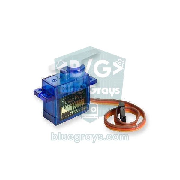
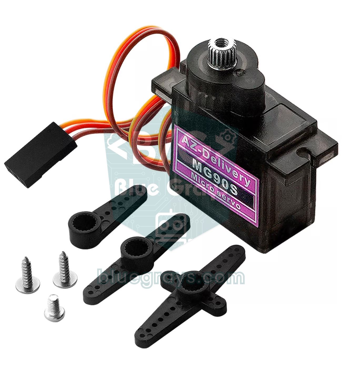
The load and the arm length decide. If you're turning a part that weighs a few grams or just experimenting, the SG90 is enough. If you want the same size with shock-resistant metal gears, pick the MG90S. If the torque you need exceeds 1 kg·cm, for example carrying 100 g at the end of a 10 cm arm, move up to the MG996R. The MG996R has about five times the torque of the SG90, but it's slower, six times heavier and draws three to four times more current, so plan the power supply and the mechanical mounting accordingly. If 11 kg·cm still isn't enough, look at bigger servos in the 20 kg·cm class such as the DS3218.
Choosing servos for a robotic arm
- Base: MG996R. Don't put the whole weight of the arm on the servo shaft; add a bearing to the base so the servo only has to rotate it.
- Shoulder: This is the joint under the most strain. Use an MG996R; if the arm is longer than 20 cm, add a 20 kg·cm class servo or a counterweight.
- Elbow: MG996R. Moving the heavy servo to shoulder level and driving the elbow with a push rod reduces the load on the shoulder.
- Wrist and wrist rotation: An MG90S is enough; using an MG996R here just adds weight for the shoulder to carry.
- Gripper: SG90 or MG90S. Set the closing angle to the point where the fingers just touch the object; a servo that keeps trying to squeeze draws stall current.
- Mounting: Fit a metal horn on the MG996R's 25-tooth shaft and secure it with the centre screw; plastic horns strip quickly at this torque.
MG996R project ideas
- Robotic arm: A 6-servo arm with MG996Rs at the base, shoulder and elbow and MG90S servos at the wrist and gripper; see the robotic arm guide for the build.
- Pan-tilt camera: Rotate an ESP32-CAM module horizontally and vertically with two MG996Rs.
- Solar tracker: Find the direction of the light with four LDRs and turn a small panel towards the sun with an MG996R; details in the solar tracker article.
- Smart trash can: A smart trash can that opens a heavy lid when a hand approaches.
- Card door lock: Pull a bolt with an MG996R when the right card is scanned on an RFID RC522.
- Joystick-controlled crane: A small crane or digger that moves on two axes with a joystick.
- Continuous drive: A slow but powerful wheel using the 360-degree version of the MG996R; the difference is explained in the 360-degree servo article.
When it's powered properly, the MG996R is a tough, inexpensive motor that easily takes on jobs small servos can't handle. Remember the rules: an external 5–6 V supply, a common GND, a capacitor close to the servo, a calibrated pulse range and smooth motion, and a PCA9685 once the servo count grows. In the BlueGrays app you'll find projects such as servo control with a potentiometer and a joystick, an ESP32 RFID door lock with a servo and a 32-servo choreography, each with a step-by-step circuit diagram and ready-to-use code.
Frequently asked questions
How much weight can an MG996R lift?
The MG996R's torque is 11 kg·cm at 6 V, which means 11 kg at 1 cm from the shaft or 1.1 kg at 10 cm. That's the stall limit where the servo stops, so plan on half of it for continuous use. In other words, it comfortably holds about 500 g at the end of a 10 cm arm.
What voltage does the MG996R need, and can I use 12 V?
According to the datasheet, the operating range is 4.8–7.2 V; in practice 5 V or 6 V is used, and 6 V gives more torque and speed. 12 V, or a 2S LiPo at 8.4 V when fully charged, will burn the servo's control board. If you have a higher-voltage source, bring it down to 6 V with a step-down converter such as the LM2596.
How many amps does the MG996R draw, and what power supply do I need?
It draws about 10 mA at rest with no load, 0.5–0.9 A while moving and up to 2.5 A when loaded and at start-up. Choose a 5–6 V adapter that delivers at least 3 A for one servo and 6–10 A for four servos. Don't forget to connect the supply's negative to the Arduino's GND pin.
Does the MG996R rotate 180 degrees, and is there a 360-degree version?
The standard MG996R is a positional servo: the manufacturer specifies about 120 degrees with standard pulses, and with a 500–2500 µs range most units get close to 180 degrees. The 360-degree version sold under the same name doesn't go to an angle; it spins continuously, changing speed and direction according to the signal. When buying, check whether the listing says 180° or 360°.
Why does my MG996R servo jitter or reset the Arduino?
The cause is almost always the power supply: when the servo is powered from the Arduino's 5V pin, its peak current pulls the voltage down and the board restarts. Use an external 5–6 V supply, a common GND and a 470–1000 µF capacitor close to the servo. For jitter while standing still, use thick wires, smooth the potentiometer readings and keep the pulse range within the servo's mechanical limits.
What's the difference between the MG996R and the MG995?
Both servos are the same size and are wired the same way; the MG996R is an improved version of the MG995. Thanks to its redesigned control board and gears, it offers a narrower dead band, steadier centring and slightly more torque. Choose the MG996R for new projects; it's a direct replacement for an old MG995.
Projects to build after reading this
See all projects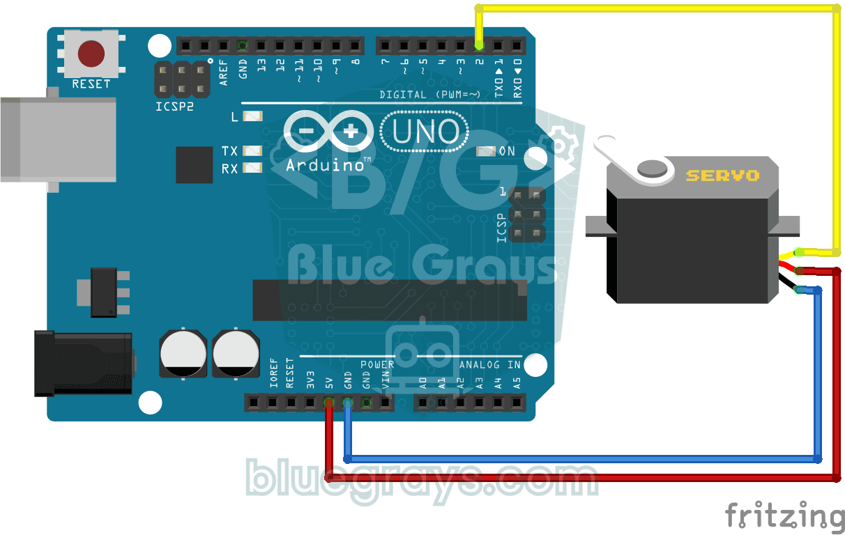
Using a Servo Motor
The arm of a small servo motor turns to three positions in turn: all the way to the start, right to the middle and all the way to the end, waiting two seconds at each stop. The Arduino tells the motor
Servo Motor Operation with Potentiometer
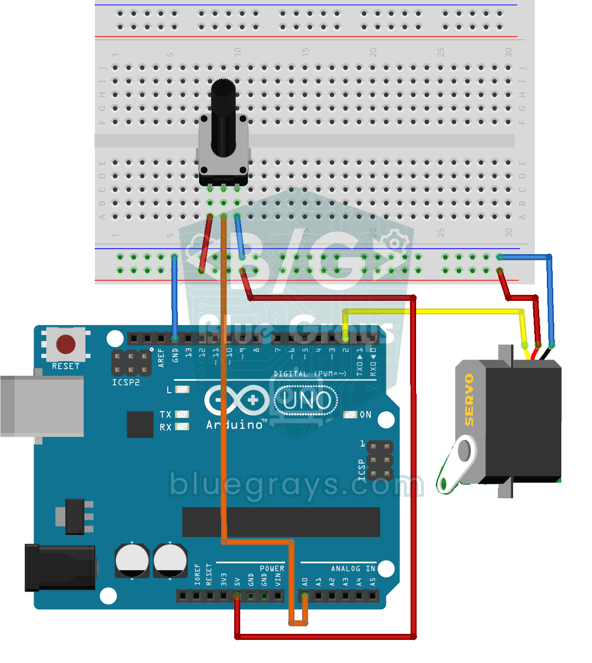
As you turn the potentiometer knob, the servo motor's arm turns right along with it: one end of the knob means zero degrees, the other end means half a turn. The Arduino keeps reading the knob's posit
Servo Control with Joystick
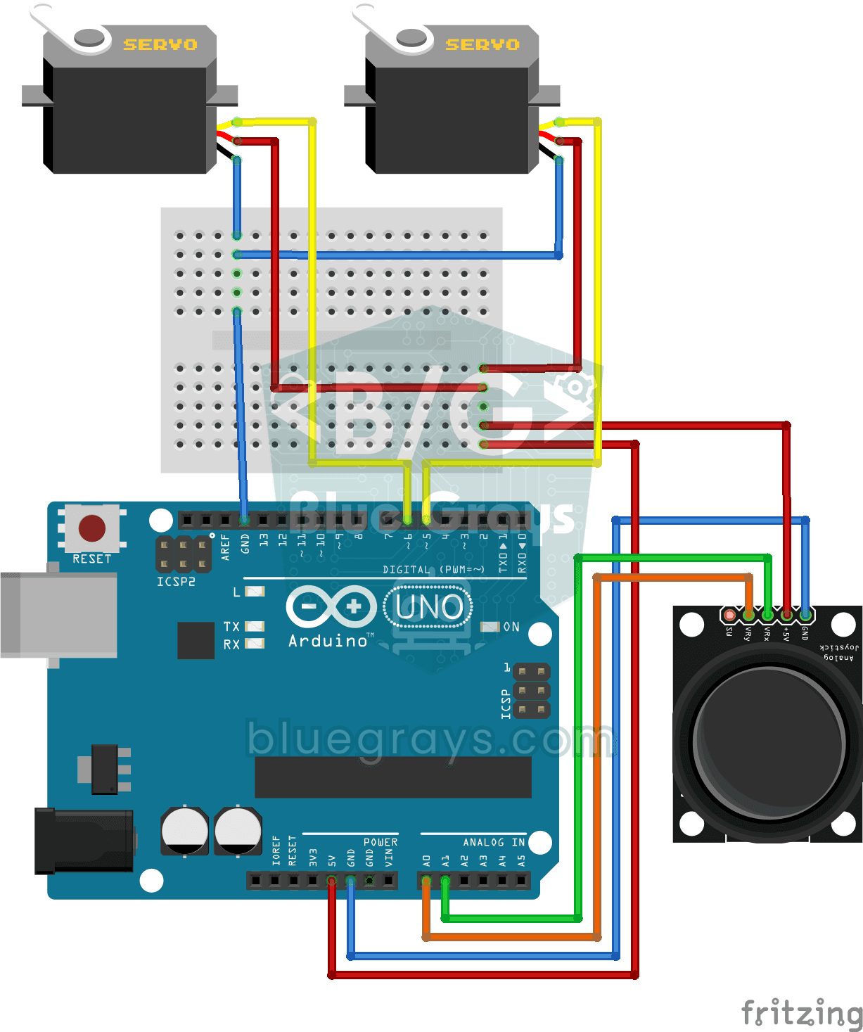
Steer two motors with a joystick, just like turning a security camera. Push the stick left or right and the bottom servo motor slowly turns, push it up or down and the top servo tilts up and down; let

ESP32 Servo Motor (Potentiometer Control)
In this project, we control an SG90 servo motor using a potentiometer. We adjust the servo angle by mapping the analog value read from the potentiometer to the 0–180-degree range. The ESP32Servo library generates servo signals on suitable output-capable GPIO pins of the ESP32; this project uses GPIO 18. This is a fundamental control method for robotic arms, camera gimbals, and automatic door mechanisms.

ESP32 RFID Door Lock (RC522 + Servo + OLED + Buzzer + LED)
We’re building a smart door lock using an ESP32, an RC522 RFID module, an SG90 servo motor, an SSD1306 OLED display, an active buzzer, and 2 LEDs. When a card is scanned, its UID is compared to the list of authorized cards stored in the code—if authorized, the servo motor rotates to unlock the door (green LED + 2 short beeps), and the door automatically locks again after 5 seconds. For an unauthorized card, the red LED lights up, a warning is given with 3 rapid beeps, and the captured UID is dis

Servo Circle Choreography - Animated Patterns with 32 Servos
A visual animation project using 32 servo motors arranged in a circle on an Arduino Mega. The servos are managed in a single array, connected to Mega's pins 22-53, and exhibit four different motion sequences: a chaotic vibration where all servos move at random angles, a synchronous sweep where they all move at the same time, a smoothly rotating wave around a circle, and finally a compass needle swinging left and right. The swirling wave effect is created by the rotation of each servo relative to

Obstacle Avoidance Robot
How about building a smart vehicle that finds its own way? The Obstacle Avoidance Robot constantly scans its surroundings thanks to the ultrasonic sensor in front of it. When it encounters an obstacle