
Servo Motor Jitter: How to Fix It on Arduino, ESP32 and Pico
Servo motor jittering, spinning on its own or resetting your Arduino? Fix it with the right power supply, common GND, capacitors and ESP32/Pico PWM settings.

Servo motor jitter is one of the most common and most confusing faults in Arduino projects: the servo buzzes and shakes where it should be still, turns by itself without any command, or the moment it moves the Arduino resets and your code starts over. The good news is that most of these symptoms don't mean the servo is broken; they come from five basic causes: insufficient power, a missing common GND, a missing capacitor, signal noise or a library conflict.
In this guide we explain why each cause happens, how to detect it with a multimeter and how to fix it permanently. You'll find current calculations for the most common servos (SG90, MG90S and MG996R), the correct wiring, Arduino code that suppresses jitter in software, PWM settings with LEDC on the ESP32 and a MicroPython solution for the Raspberry Pi Pico. If you don't know the basics of how a servo works yet, first take a look at What Is a Servo Motor?.
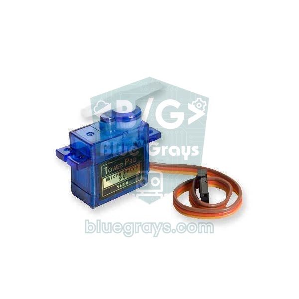
Why does a servo jitter? Understanding how it works
Inside a hobby servo there is a small DC motor, a gearbox, a potentiometer attached to the output shaft and a control circuit. The Arduino sends the servo a pulse every 20 milliseconds (50 Hz); the pulse width sets the desired angle: roughly 0.5–1 ms means 0 degrees, 1.5 ms means 90 degrees and 2–2.4 ms means 180 degrees. The control circuit compares this pulse with the real position it reads from the potentiometer and, if there's a difference, drives the motor to correct it. Because of this closed loop, the servo treats every tiny variation in pulse width as a new command. If the pulse drifts by a few microseconds, the supply voltage drops or even a bit of interference is picked up, the servo keeps correcting itself; that is the buzzing you hear and the jitter you see. Servos like the SG90 have a deadband of about 10 µs; once the variation in the signal exceeds it, the motor starts moving.
| Feature | SG90 | MG90S | MG996R |
|---|---|---|---|
| Operating voltage | 4.8–6 V | 4.8–6 V | 4.8–7.2 V |
| Gears | Plastic | Metal | Metal |
| Torque (4.8 V) | About 1.8 kg·cm | About 1.8 kg·cm | About 9.4 kg·cm |
| Running current | 100–250 mA | 150–300 mA | 500–900 mA |
| Stall current | About 650–750 mA | About 0.7–1 A | About 2.5 A |
| Recommended supply (one servo) | 5 V 1 A | 5 V 1 A | 6 V 3 A |
Symptoms and likely causes
| Symptom | Likely cause | First thing to do |
|---|---|---|
| Servo buzzes constantly and shakes slightly when idle | Noisy signal, jumpy potentiometer reading, pushing against a mechanical limit | Add a filter and deadband in code, narrow the angle range to 5–175 degrees |
| Arduino resets when the servo moves | Supply voltage collapses (brownout) | Power the servo from an external 5–6 V supply |
| Servo turns randomly by itself | No common GND, or the signal wire is floating | Connect the external supply's GND to the Arduino GND |
| Servo jumps suddenly at power-up | The 90-degree command at attach(), boot pins on the ESP32 | Set a start angle, choose a safe pin such as GPIO 18 on the ESP32 |
| Servo jitters only when another module is running | A library disables interrupts, or there's a timer conflict | Find the conflicting library, use a PCA9685 driver if needed |
| Servo strains and heats up at one end | The pulse range exceeds the servo's mechanical limit | Calibrate the pulse range with attach(pin, min, max) |
| A 360-degree servo creeps when it should stop | The centre point (about 1500 µs) has drifted | Turn the trimpot on the servo or fine-tune the stop value |
Cause 1: insufficient power and Arduino resets
The number one cause of servo jitter and resets is powering the servo from the Arduino's 5V pin. A SG90 draws only a few milliamps while waiting, but in the first milliseconds of moving, especially under load or if the shaft hits an obstacle, it can exceed 650 mA. When an Arduino Uno is powered over USB, the 5V rail is limited by the computer's USB port and the board's 500 mA self-resetting fuse. During a sudden current draw the 5V rail can fall below 4 V. Even though the ATmega328P's brownout protection only kicks in at about 2.7 V, that dip has already upset the servo control circuit, sensors and serial communication. If the voltage collapses far enough, the microcontroller restarts, the code runs from setup() again, the servo goes back to its start position, draws current again and you're stuck in a loop. This is the classic case of an Arduino resetting by itself.
Confirming the problem is easy: connect a multimeter between 5V and GND and move the servo. If the voltage you measure drops below 4.6 V, or the reading jumps around as the servo moves, the supply is the cause. To fix it, power the servos from a separate supply and base your current calculation on the stall current: for a robot arm with four SG90s, 4 × 0.7 A = 2.8 A, so an adapter of at least 5 V 3 A or an LM2596 buck converter makes sense. With powerful servos like the MG996R you should allow 2.5 A per servo. For battery operation, 4 AA cells (about 6 V with alkaline, 4.8 V with NiMH) or 6 V stepped down from a 2S Li-ion pack work well; with the battery life calculator you can see in advance how long your project will last.
Correct wiring: external power and common GND
| Servo wire | Arduino Uno | ESP32 | Raspberry Pi Pico | External 5–6 V supply |
|---|---|---|---|---|
| Brown / black (GND) | GND | GND | GND | Negative (-) |
| Red (V+) | Not connected | Not connected | Not connected | Positive (+) |
| Orange / yellow (signal) | D9 | GPIO 18 | GP15 | Not connected |
| External supply's GND | GND (common) | GND (common) | GND (common) | Negative (-) |
The most critical row in this table is the last one. The servo measures the pulse on the signal wire relative to its own GND. If the external supply's negative isn't connected to the Arduino's GND, the signal has no reference point; the servo reads stray voltages on the wires and mains-borne interference as random pulses and starts turning by itself. We explained in detail why a common ground is essential in the GND and common ground article. If you're working on a breadboard, the MB102 power module is a handy way to feed the servo rail; however, its regulator is limited to about 700–800 mA in practice, so it only suits one or two small servos at most.
Adding a capacitor: which value, and where?
Even with an external supply, every time the servo motor starts there are current pulses lasting a few milliseconds. If the wires are thin and long, these pulses create momentary dips in the voltage; the servo control circuit becomes unstable during these dips and jitter begins. The fix is to add a local energy store on the servo supply line: as close to the servo connector as possible, connect a 470–1000 µF electrolytic capacitor between positive and negative, with a 100 nF ceramic capacitor in parallel. The electrolytic capacitor supplies the large, short-lived current demand, while the ceramic one filters out the high-frequency noise produced by the motor brushes. The capacitor's voltage rating should be at least 1.5–2 times the supply voltage; for a 5–6 V servo line, a 10 V or 16 V capacitor is suitable. With several servos, putting a separate 470 µF next to each servo works better than one big capacitor.
Signal noise and wire layout
- Keep wires short: Try not to make the servo signal wire longer than 50 cm. If you have to extend it, run the signal and GND wires twisted together (twisted pair).
- Add a series resistor: Placing a 220–470 Ω resistor between the board pin and the servo signal wire reduces reflections and ringing on long lines; it also protects the pin against short circuits.
- Separate power and signal: Don't run wires carrying motor or relay current parallel to the servo signal line; if they have to cross, cross them at right angles.
- Check breadboard contact: Loose jumper wires and worn breadboard contacts cause momentary dropouts; if the jitter changes when you touch a wire, contact is the cause.
- Potentiometer noise: If you control the servo with a potentiometer, the analogRead value wobbles by a few units and that wobble goes straight into the angle. A 100 nF capacitor between the potentiometer's wiper and GND, plus a filter in code, solves this.
- 3.3 V signal: The ESP32 and Pico generate 3.3 V pulses. Most servos such as the SG90 and MG996R recognise this without trouble; for the rare servo that behaves unreliably, a logic level converter can be used.
Preventing jitter in code: filter and deadband
Even when the hardware is fine, software can make a servo jitter. The most common mistakes are calling attach() on every pass of loop(), feeding the raw potentiometer value straight into write(), and pushing the servo all the way to its physical limits (0 or 180 degrees). On cheap servos the mechanical stop is often slightly inside 0 and 180 degrees; the servo can't reach the target, keeps pushing, buzzes and heats up. The code below takes three precautions at once: it smooths the reading with an exponential average, keeps the angle within 5–175 degrees, and sends the servo a new command only when the angle has changed by at least 2 degrees. For a wider look at filtering methods, see the sensor data filtering article.
1#include <Servo.h>
2
3const int SERVO_PIN = 9;     // servo sinyal pini / servo signal pin
4const int POT_PIN = A0;      // potansiyometre orta ucu / potentiometer wiper
5const int DEADBAND = 2;      // derece cinsinden ölü bölge / dead band in degrees
6
7Servo servo;
8float filtered = 0;          // filtrelenmiş okuma / filtered reading
9int lastAngle = -1;          // son gönderilen açı / last angle sent
10
11void setup() {
12  servo.write(90);              // attach öncesi başlangıç açısı (AVR) / start angle before attach (AVR)
13  servo.attach(SERVO_PIN);      // yalnızca bir kez / only once
14  filtered = analogRead(POT_PIN);
15}
16
17void loop() {
18  int raw = analogRead(POT_PIN);
19  filtered = filtered * 0.9 + raw * 0.1;            // üstel ortalama / exponential moving average
20  int angle = map((int)filtered, 0, 1023, 5, 175);  // sınırlara dayanma / stay away from end stops
21
22  if (lastAngle < 0 || abs(angle - lastAngle) >= DEADBAND) {
23    servo.write(angle);         // yalnızca belirgin değişimde / only on a real change
24    lastAngle = angle;
25  }
26  delay(15);
27}| Line / command | What it does |
|---|---|
| servo.write(90) (before attach) | Makes the first pulse start at 90 degrees in the standard AVR Servo library; it reduces the jump at power-up. |
| filtered = filtered * 0.9 + raw * 0.1 | Exponential moving average: suppresses sudden wobbles and lets slow changes through. The smaller the 0.1 coefficient, the stronger the filter but the slower the response. |
| map(..., 5, 175) | Runs the servo without pushing it against its mechanical stops. |
| DEADBAND = 2 | Doesn't send a new command if the angle changed by less than 2 degrees; the deadband cuts small jitters. |
| delay(15) | Gives the servo time to reach the new position and limits the reading rate. |
| attach(pin, 500, 2400) | Used to calibrate the pulse range to the servo's real limits; the defaults are 544 and 2400 µs. |
| servo.detach() | Stops the pulses once the servo reaches its target; the buzzing stops but the servo loses its holding torque. |
Library and timer conflicts
The standard Servo library on the Arduino Uno generates pulses using the hardware Timer1 and interrupts. This design lets one timer drive up to 12 servos, but it has two side effects: it can't run together with another library that uses Timer1, and the accuracy of the pulses depends on interrupts running on time. Any code that disables interrupts for a few hundred microseconds stretches the pulse being generated at that moment and the servo twitches. If the jitter starts only when a certain module kicks in, you are almost certainly facing this situation.
- analogWrite on pins 9 and 10: When the Servo library is used, PWM doesn't work on these two pins on the Uno; move any LED or motor driver connected to them to pin 3, 5, 6 or 11.
- 433 MHz RF libraries: VirtualWire and RadioHead's RH_ASK driver also use Timer1 by default; you'll see compile errors or erratic servo movement. See the 433 MHz RF module article for details.
- NeoPixel strips: Adafruit NeoPixel and FastLED disable interrupts while sending data; on a long strip this lasts milliseconds and the servo twitches on every update. If a WS2812B and a servo are used together, update the strip less often.
- SoftwareSerial and DHT: Both briefly disable interrupts while receiving bytes or reading the sensor; this is a frequent cause of the jitter seen on servo arms controlled by a Bluetooth module.
- The permanent fix: Use a PCA9685 servo driver that generates the pulses with its own hardware; that way jitter-free signals go to up to 16 servos no matter what the Arduino is doing.
Servo PWM settings on the ESP32
The standard Arduino Servo library doesn't work on the ESP32; instead you use the ESP32Servo library or the built-in LEDC PWM unit directly. Because LEDC is hardware-based, it isn't affected by interrupts and produces very stable pulses; the only requirement is to set the frequency to 50 Hz and the resolution to a sufficient value. At 14-bit resolution the 20 ms period is divided into 16384 steps; each step is about 1.22 µs, which is more than precise enough for a servo. We chose 14 bits because newer chips such as the ESP32-S3 and ESP32-C3 support this value too. Because the LEDC functions changed in version 3.x of the ESP32 Arduino core, the code below is written to compile with both versions:
1// ESP32 Arduino core 2.x ve 3.x uyumlu / compatible with ESP32 Arduino core 2.x and 3.x
2const int SERVO_PIN = 18;      // güvenli bir GPIO / a safe GPIO
3const int PWM_FREQ = 50;       // 50 Hz = 20 ms periyot / 20 ms period
4const int PWM_BITS = 14;       // ESP32, S3 ve C3 destekler / supported by ESP32, S3 and C3
5const int MIN_US = 500;        // 0 derece darbesi / 0 degree pulse
6const int MAX_US = 2400;       // 180 derece darbesi / 180 degree pulse
7
8#if ESP_ARDUINO_VERSION_MAJOR < 3
9const int PWM_CHANNEL = 0;     // 2.x için LEDC kanalı / LEDC channel for 2.x
10#endif
11
12uint32_t usToDuty(uint32_t us) {
13  return us * ((1UL << PWM_BITS) - 1) / 20000UL;  // mikrosaniyeyi duty değerine çevir / convert microseconds to duty
14}
15
16void servoWriteUs(uint32_t us) {
17#if ESP_ARDUINO_VERSION_MAJOR >= 3
18  ledcWrite(SERVO_PIN, usToDuty(us));     // 3.x: pin numarası / pin number
19#else
20  ledcWrite(PWM_CHANNEL, usToDuty(us));   // 2.x: kanal numarası / channel number
21#endif
22}
23
24void servoWriteAngle(int angle) {
25  angle = constrain(angle, 0, 180);
26  servoWriteUs(map(angle, 0, 180, MIN_US, MAX_US));
27}
28
29void setup() {
30#if ESP_ARDUINO_VERSION_MAJOR >= 3
31  ledcAttach(SERVO_PIN, PWM_FREQ, PWM_BITS);
32#else
33  ledcSetup(PWM_CHANNEL, PWM_FREQ, PWM_BITS);
34  ledcAttachPin(SERVO_PIN, PWM_CHANNEL);
35#endif
36  servoWriteAngle(90);           // başlangıç konumu / start position
37}
38
39void loop() {
40  for (int a = 30; a <= 150; a++) {   // yumuşak tarama / smooth sweep
41    servoWriteAngle(a);
42    delay(15);
43  }
44  for (int a = 150; a >= 30; a--) {
45    servoWriteAngle(a);
46    delay(15);
47  }
48}
There are two more ESP32-specific traps. The first is boot pins: pins such as GPIO 0, 2, 12, 14 and 15, as well as serial port pins 1 and 3, can produce short pulses during boot; if the servo is on these pins, it jumps at every reset. GPIO 13, 18, 19, 23, 25, 26, 27, 32 and 33 are safe choices for servos; pins 34–39 are input-only and can't drive a servo. The second is supply sensitivity: with Wi-Fi on, the ESP32 already draws current pulses above 300 mA, and if the servo is powered from the same rail you'll see the message "Brownout detector was triggered" in the serial monitor. We covered the fix for this error in the ESP32 brownout and Guru Meditation article; in short, power the servo from a separate supply and join the GNDs.
Servo on the Raspberry Pi Pico (MicroPython)
Every GPIO pin on the Raspberry Pi Pico can generate hardware PWM; the chip has 8 PWM slices and 16 channels in total. In MicroPython, once you set the PWM object's frequency to 50 Hz, you can give the pulse width directly in nanoseconds with duty_ns(); this is much safer than fiddling with percentages or 16-bit duty calculations. The code below controls the servo on GP15 with the potentiometer on GP26 and applies exactly the same filter and deadband logic as the Arduino example. The Pico's 3V3 output isn't suitable for powering a servo in terms of either voltage or current; power the servo from an external 5 V supply and make the GND common.
1from machine import Pin, PWM, ADC
2import time
3
4servo = PWM(Pin(15))          # servo sinyali GP15 / servo signal on GP15
5servo.freq(50)                # 50 Hz = 20 ms
6pot = ADC(26)                 # potansiyometre GP26 (ADC0) / potentiometer on GP26 (ADC0)
7
8MIN_US = 500                  # 0 derece / 0 degrees
9MAX_US = 2400                 # 180 derece / 180 degrees
10DEADBAND = 2                  # ölü bölge (derece) / dead band (degrees)
11
12def write_angle(angle):
13    angle = max(5, min(175, angle))              # sınırlara dayanma / stay away from end stops
14    us = MIN_US + (MAX_US - MIN_US) * angle // 180
15    servo.duty_ns(us * 1000)                     # mikrosaniye -> nanosaniye / microseconds -> nanoseconds
16
17filtered = pot.read_u16()
18last = -100
19write_angle(90)               # başlangıç konumu / start position
20
21while True:
22    filtered = filtered * 0.9 + pot.read_u16() * 0.1   # üstel ortalama / exponential moving average
23    angle = int(filtered * 180 / 65535)
24    if abs(angle - last) >= DEADBAND:
25        write_angle(angle)
26        last = angle
27    time.sleep_ms(20)
Step-by-step checklist
- Disconnect the servo from the board and power it only from an external 5–6 V supply; make sure the supply's current covers the number of servos × stall current.
- Connect the external supply's GND to the GND of the Arduino, ESP32 or Pico; this single wire ends most "turning by itself" problems.
- While the servo is moving, measure the supply voltage with a multimeter; if it drops below 4.6 V, use a stronger supply or thicker wires.
- Add a 470–1000 µF electrolytic and a 100 nF ceramic capacitor next to the servo connector and check the polarity.
- Shorten the signal wire, add a 220–470 Ω series resistor if needed and make the breadboard contacts solid.
- In the code, check that attach() is called only in setup(), that the angle stays within 5–175 degrees and that you use a filter and deadband.
- If the servo jitters when another module runs, find the conflict by disabling libraries one at a time; switch to a PCA9685 if needed.
- If it still jitters, try swapping in a different servo; servos with a worn potentiometer or broken gears will jitter under any conditions.
Things to watch for in servo projects
- Robot arm: On a robot arm with four or six servos, don't move all the servos at once; sequence the commands 100–200 ms apart so the current peaks don't stack up.
- Radar project: In projects that scan continuously, like an Arduino radar, turn the servo degree by degree and wait 15–30 ms at each step; sudden big jumps mean both jitter and a current spike.
- Heavy loads: For jobs that carry a load, such as a door lock or a camera mount, use a metal-gear MG996R instead of an SG90 and choose a supply of at least 3 A.
- Continuous-rotation servos: If 360-degree servos like the FS90R creep at the stop point, that's not jitter but a calibration problem; fine-tune the stop value around 1500 µs.
- Battery-powered projects: Releasing the servo with detach() when the movement is finished both stops the buzzing and extends battery life; it's very effective if the mechanism doesn't slip under its own weight.
Servo jitter may look complicated at first, but it is almost always solved in the same order: first power, then common GND, then the capacitor, then wiring and software last. If you follow this order you'll rarely need to replace the servo itself. For the details of power calculations, you can also check the Arduino power supply guide. In the BlueGrays app you'll find the circuit diagrams and code step by step for projects such as potentiometer servo control, joystick servo, ESP32 servo and an RFID door lock, so you can put what you learn here to use right away.
Frequently asked questions
Why does a servo motor jitter?
The most common cause of servo jitter is an insufficient or fluctuating supply voltage; when the servo is powered from the Arduino's 5V pin, the voltage drops during sudden current draws and the control circuit becomes unstable. A missing common GND, a noisy signal, jumpy potentiometer values and forcing the servo against its mechanical limit can also cause it. An external 5–6 V supply, a common GND and a 470–1000 µF capacitor solve most problems.
Why does my servo motor turn by itself?
If the servo turns with no command, the signal line usually has no reference: the external supply's GND isn't connected to the Arduino GND, or the signal wire is loose. The servo then treats interference on the wires as pulses. With 360-degree servos, slow rotation comes from the centre point (about 1500 µs) calibration drifting, and it's corrected with the trimpot on the servo.
Why does my Arduino reset when the servo runs?
When it starts moving, a servo can draw hundreds of milliamps, and over 2 A on big servos. If this current is drawn from the Arduino's USB or regulator line, the 5 V collapses and the microcontroller restarts. Once you power the servo from a separate supply and only join the GNDs, the resets stop.
How many µF of capacitor should I use for a servo?
For a single SG90 or MG90S, 470 µF near the servo connector is a good start; for large servos like the MG996R, use a 1000 µF electrolytic capacitor. Adding a 100 nF ceramic capacitor beside it also filters high-frequency noise. The capacitor's voltage rating should be at least 10 V for a 5–6 V line, and the polarity must be connected correctly.
Can I power a servo motor from the Arduino 5V pin?
For testing a single SG90 with no load, the 5V pin is often enough, but it isn't a reliable solution. The USB line is limited to about 500 mA and a stalled servo exceeds that. If you use two or more servos, a servo carrying a load, or an MG996R, always use an external supply.
Why does my servo jitter or not work on the ESP32?
The standard Arduino Servo library doesn't work on the ESP32; you need to use the ESP32Servo library or LEDC PWM set to 50 Hz. Connecting the servo to boot pins such as GPIO 0, 2, 12 or 15 causes jumps at reset, and powering it from the ESP32's own rail causes brownout errors. A safe pin such as GPIO 18 and a separate 5 V supply solve the problem.
Projects to build after reading this
See all projects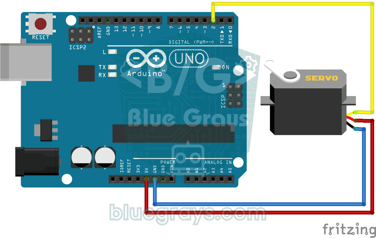
Using a Servo Motor
The arm of a small servo motor turns to three positions in turn: all the way to the start, right to the middle and all the way to the end, waiting two seconds at each stop.
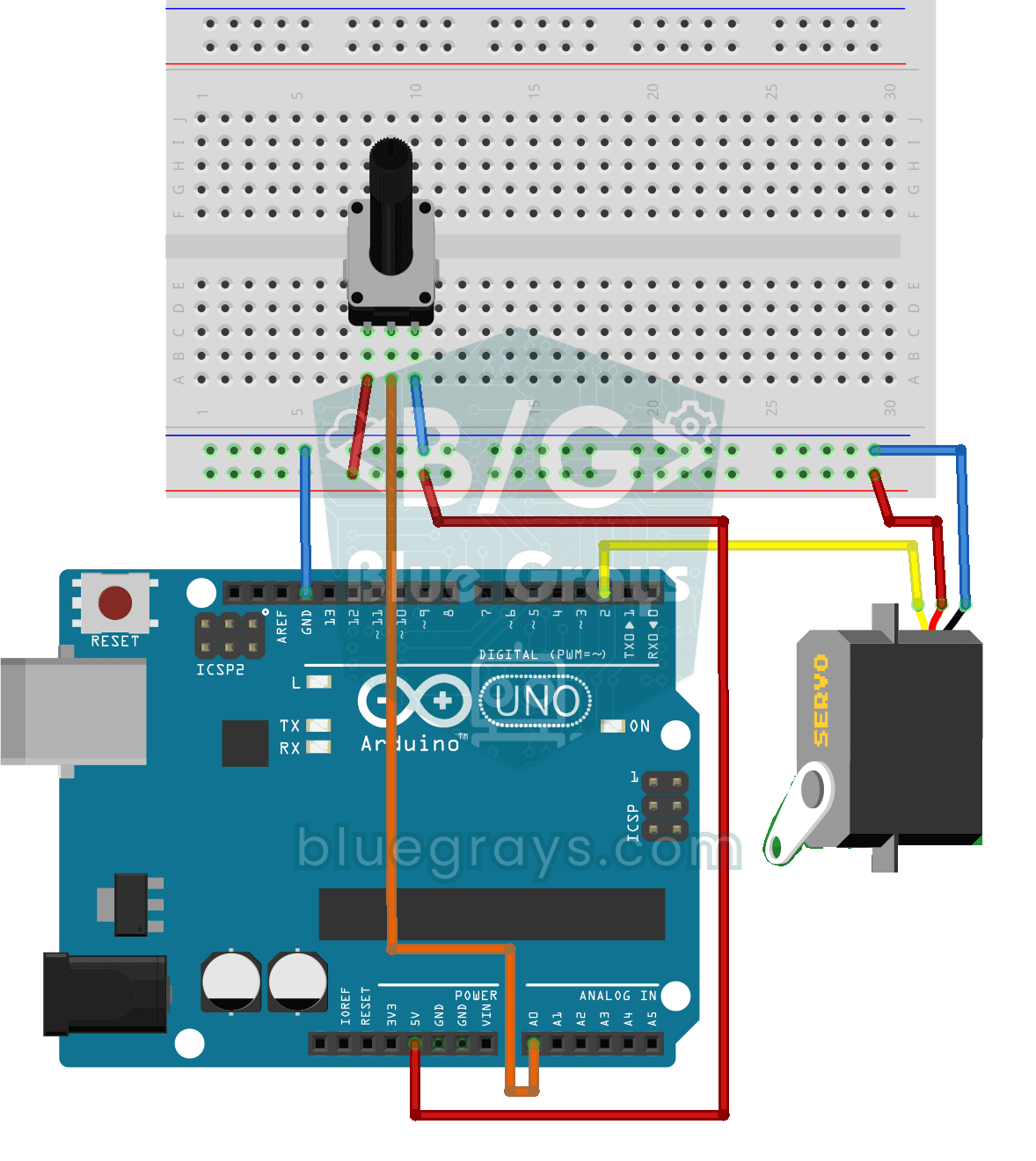
Servo Motor Operation with Potentiometer
As you turn the potentiometer knob, the servo motor's arm turns right along with it: one end of the knob means zero degrees, the other end means half a turn.
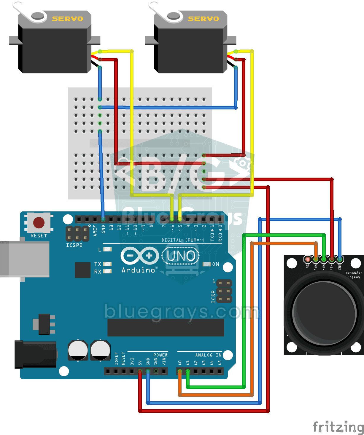
Servo Control with Joystick
Steer two motors with a joystick, just like turning a security camera. Push the stick left or right and the bottom servo motor slowly turns, push it up or down and the top servo tilts up and down…

ESP32 Servo Motor (Potentiometer Control)
In this project, we control an SG90 servo motor using a potentiometer. We adjust the servo angle by mapping the analog value read from the potentiometer to the 0–180-degree range. The ESP32Servo library generates servo signals on suitable output-capable GPIO pins of the ESP32; this project uses GPIO 18. This is a fundamental control method for robotic arms, camera gimbals, and automatic door mechanisms.

ESP32 RFID Door Lock (RC522 + Servo + OLED + Buzzer + LED)
We build a smart door lock with an ESP32, an RC522 RFID module, an SG90 servo, an SSD1306 OLED display, an active buzzer and 2 LEDs. When a card is scanned, its UID is checked against the authorized cards defined in the code; if it matches, the servo unlocks (green LED + 2 short beeps) and locks again after 5 seconds. An unknown card lights the red LED, gives 3 quick beeps and shows its UID on the OLED.
360-Degree Servo from a Stepper Motor
Teach an ordinary stepper motor to go to any angle you want, all the way around the circle.

Servo Circle Choreography - Animated Patterns with 32 Servos
A visual animation project driven by 32 servo motors arranged in a circle on an Arduino Mega. The servos are managed in a single array, connected to the Mega's pins 22–53, and perform four motion sequences: a chaotic jitter at random angles, a synchronized sweep, a wave travelling around the circle and a compass needle swinging left and right.