
Arduino Fan Speed Control: Temperature-Based PWM Fan Control
Arduino fan speed control: drive a 2-wire fan with a MOSFET, run a 4-pin PC fan at 25 kHz PWM and read RPM from the tach. Uno, ESP32 and Pico code, plus a curve.

Arduino fan speed control is the most practical way to adjust a fan automatically by temperature: a sensor measures the environment, the Arduino turns that reading into a speed and drives the fan with a PWM signal. The fan turns slowly and quietly when it's cool, speeds up as the heat rises and doesn't make needless noise at full speed. 3D printer enclosures, power supply boxes, aquarium lids, greenhouses and computer cases are where this method is used most often.
This guide covers two different approaches: driving a simple 2-wire fan with PWM through a logic-level MOSFET, and controlling a 4-pin PC fan from its own control line with 25 kHz PWM while reading its speed from the tach (tachometer) output. You'll go step by step through working code for the Arduino Uno, ESP32 and Raspberry Pi Pico, building a temperature-speed curve with map, hysteresis, and the tricks for running the fan truly quietly.
What is fan control with Arduino, and how does it work?
Computer fans are brushless DC motors; a small driver circuit inside energizes the coils in turn. There are two ways to change a fan's speed: lower the applied voltage, or switch the voltage on and off very quickly. The second method is PWM, and it's the native language of microcontrollers. At a 50% duty cycle the fan receives power half of the time; the propeller's inertia smooths out these pulses and the fan spins at roughly half speed. You can find the basics of PWM in detail in What Is PWM?. What matters most is how many wires your fan has, because that determines the circuit you'll build.
| Feature | 2-wire fan | 3-wire fan | 4-pin PWM fan |
|---|---|---|---|
| Wires | Red (+), black (GND) | +, GND, yellow or green tach | GND, +12 V, tach, PWM |
| Speed control | PWM the supply with a MOSFET | PWM the supply or lower the voltage | Separate PWM line, 25 kHz |
| Speed reading | None | Yes (gets corrupted during PWM) | Yes, independent of PWM |
| Extra parts needed | MOSFET, diode, resistors | MOSFET, diode, resistors | Only a 10 kΩ pull-up |
| Lowest speed | Stops below 30–40% duty | Stops below 30–40% duty | Usually keeps spinning at 20–30% speed |
| Typical use | Case and appliance fans | Old PC fans | Modern PC and CPU fans |
Driving a 2-wire fan with PWM through a MOSFET
An Arduino pin gives 5 V and can safely supply only about 20 mA; it can't drive a 12 V fan drawing 0.1–0.3 A directly. So we put an N-channel MOSFET in between and use it as a low-side switch: the fan's red wire goes to the external 12 V, its black wire goes to the MOSFET's drain (D) pin, and the source (S) pin connects to GND. The Arduino pin drives the gate (G) through a 220 Ω resistor. A 10 kΩ resistor between gate and source stops the fan from running on its own while the Arduino powers up or resets. A diode across the fan's two terminals, in reverse (cathode on the +12 V side), absorbs the voltage spike the motor coil produces when switching off. We explain how a MOSFET works in more detail in Using a MOSFET with Arduino.
| Part | Recommended value | Purpose |
|---|---|---|
| N-channel MOSFET (Uno, 5 V) | IRLZ44N, IRL540N, IRLB8721 | Switches the fan's GND line on and off with PWM |
| N-channel MOSFET (ESP32/Pico, 3.3 V) | AO3400, IRLML2502 | Turns fully on at a 3.3 V gate voltage |
| Gate resistor | 100–220 Ω | Limits pin current, reduces ringing in the signal |
| Gate pull-down | 10 kΩ (between gate and source) | Keeps the MOSFET off at power-up |
| Flyback diode | 1N5819 (Schottky) or 1N4007 | Absorbs the voltage spike from the coil |
| Supply | 12 V adapter, at least 2× the fan current | Powers the fan independently of the Arduino |
Wiring table: Arduino Uno, ESP32 and Pico
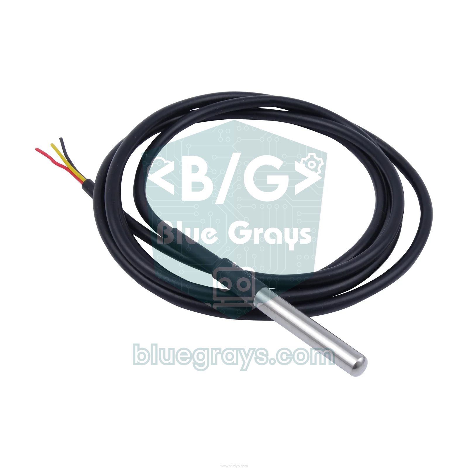
The table below covers both the direct connection of a 4-pin fan and the MOSFET gate for a 2-wire fan; in both circuits the PWM comes from the same pin. As the temperature sensor we use the DS18B20, which works on all the boards and also comes in a waterproof version; details are in DS18B20 Temperature Sensor.
| Connection | Arduino Uno | ESP32 | Raspberry Pi Pico |
|---|---|---|---|
| Fan PWM (blue) or MOSFET gate | D9 | GPIO 25 | GP16 |
| Fan tach (green) + 10 kΩ pull-up | D2 (pull-up to 5V) | GPIO 26 (pull-up to 3V3) | GP17 (pull-up to 3V3) |
| DS18B20 data + 4.7 kΩ pull-up | D4 | GPIO 4 | GP15 |
| DS18B20 VDD | 5V | 3V3 | 3V3 |
| Fan +12 V (yellow) | External 12 V adapter | External 12 V adapter | External 12 V adapter |
| Fan GND (black) | GND (common with adapter) | GND (common with adapter) | GND (common with adapter) |
Step by step: driving a 2-wire fan by temperature (Arduino Uno)
- In the Arduino IDE, install the OneWire and DallasTemperature libraries from the Library Manager.
- Connect the DS18B20: VDD to 5V, GND to GND, the data pin to D4; place a 4.7 kΩ resistor between the data pin and 5V.
- Build the MOSFET circuit: the fan's red wire to +12 V, black to the drain, source to GND, gate to D9 through 220 Ω, and 10 kΩ between gate and source.
- Place the diode across the fan's terminals in reverse: the striped cathode end to +12 V, the other end to the fan's black wire.
- Connect the adapter's GND to the Arduino GND, upload the code and open the Serial Monitor at 9600 baud.
- Warm the sensor with your fingers; once it passes 30 °C, watch the fan start with a short full-power pulse and then speed up with the temperature.
1#include <OneWire.h>
2#include <DallasTemperature.h>
3
4const byte FAN_PIN  = 9;     // MOSFET gate (220 ohm) / MOSFET gate (220 ohm)
5const byte TEMP_PIN = 4;     // DS18B20 veri / DS18B20 data
6
7const float T_ON    = 30.0;  // fan bu sıcaklıkta açılır / fan turns on here
8const float T_OFF   = 27.0;  // fan bu sıcaklıkta kapanır / fan turns off here
9const float T_MAX   = 45.0;  // tam hız sıcaklığı / full speed temperature
10const int   PWM_MIN = 80;    // fanın dönebildiği en düşük değer / lowest value that keeps the fan spinning
11
12OneWire oneWire(TEMP_PIN);
13DallasTemperature sensors(&oneWire);
14bool fanOn = false;
15int lastPwm = 0;
16
17void setup() {
18  Serial.begin(9600);
19  pinMode(FAN_PIN, OUTPUT);
20  // Timer1 ön bölücü = 1: D9 ve D10'da ~31 kHz PWM / Timer1 prescaler = 1: ~31 kHz PWM on D9 and D10
21  TCCR1B = (TCCR1B & 0b11111000) | 0x01;
22  sensors.begin();
23}
24
25void loop() {
26  sensors.requestTemperatures();               // ~750 ms sürer / takes ~750 ms
27  float t = sensors.getTempCByIndex(0);
28  int pwm;
29
30  if (t == DEVICE_DISCONNECTED_C) {
31    pwm = 255;                                 // sensör yok: tam hız / no sensor: full speed
32  } else {
33    if (!fanOn && t >= T_ON)  fanOn = true;    // histerezis / hysteresis
34    if (fanOn && t <= T_OFF)  fanOn = false;
35    if (fanOn) {
36      float tc = constrain(t, T_OFF, T_MAX);
37      pwm = map((long)(tc * 10), (long)(T_OFF * 10), (long)(T_MAX * 10), PWM_MIN, 255);
38    } else {
39      pwm = 0;
40    }
41  }
42
43  if (lastPwm == 0 && pwm > 0) {               // kalkış darbesi / kick start
44    analogWrite(FAN_PIN, 255);
45    delay(500);
46  }
47  analogWrite(FAN_PIN, pwm);
48  lastPwm = pwm;
49
50  Serial.print(F("Sicaklik: "));
51  Serial.print(t, 1);
52  Serial.print(F(" C  PWM: "));
53  Serial.println(pwm);
54  delay(250);
55}| Line / setting | What it does |
|---|---|
| TCCR1B = (TCCR1B & 0b11111000) | 0x01 | Sets the Timer1 prescaler to 1; PWM on D9 and D10 rises from 490 Hz to about 31.4 kHz and the fan whine becomes inaudible |
| T_ON / T_OFF | Hysteresis: the fan turns on at 30 °C but only turns off when it drops to 27 °C; no on-off flutter at the threshold temperature |
| map(...) | Maps the 27–45 °C range linearly onto the 80–255 PWM range; values are multiplied by 10 so the decimal part isn't lost |
| PWM_MIN = 80 | The lowest value at which the fan keeps spinning (about 31%); find it by experiment for your own fan |
| Kick start | When the fan is stopped, full power is applied for 0.5 seconds first; fans that can't start at low duty begin safely this way |
| DEVICE_DISCONNECTED_C | If the sensor disconnects or can't be read, the fan goes to full speed; the device doesn't overheat in case of a fault |
Temperature-speed curve with map and hysteresis
A temperature-speed curve defines which speed to apply at which temperature. The simplest form is a two-point linear curve: the lowest speed at the lower temperature, full speed at the upper temperature, and a straight line in between. Arduino's map() function does exactly this; but since it works with integers, converting a value like 31.6 °C to 316 before passing it preserves precision. Because map also extends values outside the range linearly, you need to limit the input with constrain() first; otherwise at 60 °C you'd get a meaningless value above 255. The function's details are in Arduino map Function. The table below shows the values the curve takes for a 25–45 °C range and a 20% minimum speed; the slope is 4% per degree.
| Temperature | Fan speed (%) | 8-bit PWM (0–255) | Uno Timer1 OCR1A (0–320) |
|---|---|---|---|
| 25 °C and below | 20 | 51 | 64 |
| 30 °C | 40 | 102 | 128 |
| 35 °C | 60 | 153 | 192 |
| 40 °C | 80 | 204 | 256 |
| 45 °C and above | 100 | 255 | 320 |
4-pin PC fan: 25 kHz PWM and reading the tach
4-pin fans follow Intel's fan standard: pin 1 is GND (black), pin 2 is +12 V (yellow), pin 3 is tach (green), pin 4 is PWM control (blue). The fan is always powered with the full 12 V; the PWM signal on the blue line sets the speed, and the standard asks for a frequency of 25 kHz for this signal (21–28 kHz is accepted). Inside the fan there's a resistor that pulls the PWM line up, so if the line is left floating the fan spins at full speed. The tach output produces 2 pulses per revolution. You count the pulses with an interrupt and calculate the speed with this formula: RPM = (pulse count ÷ 2) × (60 ÷ measurement time in seconds). If you count 40 pulses in 1 second, the fan is spinning at 1200 RPM.
1#include <OneWire.h>
2#include <DallasTemperature.h>
3
4const byte PWM_PIN  = 9;        // OC1A -> fan mavi kablo / fan blue wire
5const byte TACH_PIN = 2;        // INT0 -> fan yeşil kablo / fan green wire
6const byte TEMP_PIN = 4;        // DS18B20 veri / DS18B20 data
7const uint16_t PWM_TOP = 320;   // 16 MHz / (2 * 320) = 25 kHz
8
9const float T_MIN = 25.0;       // altında en düşük hız / minimum speed below this
10const float T_MAX = 45.0;       // üstünde tam hız / full speed above this
11const byte DUTY_MIN = 20;       // yüzde / percent
12
13OneWire oneWire(TEMP_PIN);
14DallasTemperature sensors(&oneWire);
15
16volatile uint16_t tachPulses = 0;
17unsigned long lastCalc = 0;
18
19void tachISR() {
20  tachPulses++;                 // her düşen kenar bir darbe / each falling edge is one pulse
21}
22
23void setFanPercent(byte percent) {
24  if (percent > 100) percent = 100;
25  OCR1A = (uint32_t)PWM_TOP * percent / 100;
26}
27
28void setup() {
29  Serial.begin(9600);
30  pinMode(PWM_PIN, OUTPUT);
31  TCCR1A = 0;
32  TCCR1B = 0;
33  TCNT1  = 0;
34  TCCR1A = _BV(COM1A1) | _BV(WGM11);   // OC1A normal çıkış, mod 10 / OC1A non-inverting, mode 10
35  TCCR1B = _BV(WGM13) | _BV(CS10);     // faz doğru PWM, TOP = ICR1, ön bölücü 1 / phase correct, TOP = ICR1, prescaler 1
36  ICR1 = PWM_TOP;
37  setFanPercent(DUTY_MIN);
38
39  pinMode(TACH_PIN, INPUT_PULLUP);      // harici 10k pull-up önerilir / external 10k pull-up recommended
40  attachInterrupt(digitalPinToInterrupt(TACH_PIN), tachISR, FALLING);
41  sensors.begin();
42  lastCalc = millis();
43}
44
45void loop() {
46  sensors.requestTemperatures();
47  float t = sensors.getTempCByIndex(0);
48
49  byte duty;
50  if (t == DEVICE_DISCONNECTED_C) {
51    duty = 100;                         // sensör yok: tam hız / no sensor: full speed
52  } else {
53    float tc = constrain(t, T_MIN, T_MAX);
54    duty = map((long)(tc * 10), (long)(T_MIN * 10), (long)(T_MAX * 10), DUTY_MIN, 100);
55  }
56  setFanPercent(duty);
57
58  unsigned long now = millis();
59  unsigned long elapsed = now - lastCalc;
60  lastCalc = now;
61  noInterrupts();
62  uint16_t pulses = tachPulses;
63  tachPulses = 0;
64  interrupts();
65  unsigned long rpm = (unsigned long)pulses * 30000UL / elapsed;   // 2 darbe = 1 tur / 2 pulses = 1 turn
66
67  Serial.print(F("Sicaklik: "));
68  Serial.print(t, 1);
69  Serial.print(F(" C  Duty: %"));
70  Serial.print(duty);
71  Serial.print(F("  RPM: "));
72  Serial.println(rpm);
73  delay(1000);
74}
Arduino's analogWrite function can't produce 25 kHz, so we configure Timer1 directly. When mode 10 (phase-correct PWM, top value ICR1) is selected, the frequency is 16 MHz ÷ (2 × 1 × ICR1); ICR1 = 320 gives exactly 25 kHz. The duty value is written to the OCR1A register between 0 and 320, so each step is about 0.3%. The tach line is connected to the INT0 interrupt on D2; the counter increases by one on every falling edge. In loop, interrupts are disabled for a very short time so the counter can be safely read and reset. You can find the logic of interrupts in Arduino Interrupt.
Fan control with the ESP32 (25 kHz with LEDC)
On the ESP32 the LEDC unit is used for PWM, and you can set 25 kHz in a single line; thanks to the 80 MHz clock, 8-bit resolution is easily achieved at this frequency. In Arduino core 3.x the LEDC functions work with the pin number, while in 2.x they work with the channel number; the code below compiles on both versions thanks to an ESP_ARDUINO_VERSION_MAJOR check. On the ESP32 every GPIO can take an interrupt; we use GPIO 26 for the tach and protect the counter with a critical section (portMUX) so it isn't accessed from inside and outside the interrupt at the same time. If you're using a 2-wire fan, you can connect GPIO 25 to the gate of a MOSFET that turns fully on at 3.3 V and use the same code; in that case, ignore the tach lines.
1#include <OneWire.h>
2#include <DallasTemperature.h>
3
4const int PWM_PIN  = 25;      // fan mavi kablo / fan blue wire
5const int TACH_PIN = 26;      // fan yeşil kablo (10k -> 3V3) / fan green wire (10k -> 3V3)
6const int TEMP_PIN = 4;       // DS18B20 veri / DS18B20 data
7const int PWM_FREQ = 25000;   // 25 kHz
8const int PWM_RES  = 8;       // 0-255
9const int PWM_CH   = 0;       // yalnız core 2.x / core 2.x only
10
11const float T_MIN = 25.0;
12const float T_MAX = 45.0;
13const int DUTY_MIN = 51;      // ~%20 / ~20 %
14
15OneWire oneWire(TEMP_PIN);
16DallasTemperature sensors(&oneWire);
17
18volatile uint32_t tachPulses = 0;
19portMUX_TYPE tachMux = portMUX_INITIALIZER_UNLOCKED;
20unsigned long lastCalc = 0;
21
22void IRAM_ATTR tachISR() {
23  portENTER_CRITICAL_ISR(&tachMux);
24  tachPulses++;
25  portEXIT_CRITICAL_ISR(&tachMux);
26}
27
28void fanWrite(int duty) {
29#if ESP_ARDUINO_VERSION_MAJOR >= 3
30  ledcWrite(PWM_PIN, duty);           // core 3.x: pin ile / by pin
31#else
32  ledcWrite(PWM_CH, duty);            // core 2.x: kanal ile / by channel
33#endif
34}
35
36void setup() {
37  Serial.begin(115200);
38#if ESP_ARDUINO_VERSION_MAJOR >= 3
39  ledcAttach(PWM_PIN, PWM_FREQ, PWM_RES);
40#else
41  ledcSetup(PWM_CH, PWM_FREQ, PWM_RES);
42  ledcAttachPin(PWM_PIN, PWM_CH);
43#endif
44  fanWrite(DUTY_MIN);
45  pinMode(TACH_PIN, INPUT_PULLUP);
46  attachInterrupt(digitalPinToInterrupt(TACH_PIN), tachISR, FALLING);
47  sensors.begin();
48  lastCalc = millis();
49}
50
51void loop() {
52  sensors.requestTemperatures();
53  float t = sensors.getTempCByIndex(0);
54  int duty;
55  if (t == DEVICE_DISCONNECTED_C) {
56    duty = 255;                       // sensör yok: tam hız / no sensor: full speed
57  } else {
58    float tc = constrain(t, T_MIN, T_MAX);
59    duty = map((long)(tc * 10), (long)(T_MIN * 10), (long)(T_MAX * 10), DUTY_MIN, 255);
60  }
61  fanWrite(duty);
62
63  unsigned long now = millis();
64  unsigned long elapsed = now - lastCalc;
65  lastCalc = now;
66  portENTER_CRITICAL(&tachMux);
67  uint32_t pulses = tachPulses;
68  tachPulses = 0;
69  portEXIT_CRITICAL(&tachMux);
70  unsigned long rpm = (unsigned long)pulses * 30000UL / elapsed;   // 2 darbe = 1 tur / 2 pulses = 1 turn
71
72  Serial.printf("Sicaklik: %.1f C  Duty: %d%%  RPM: %lu\n", t, duty * 100 / 255, rpm);
73  delay(1000);
74}
Fan control with the Raspberry Pi Pico and MicroPython
The Pico's PWM hardware easily produces 25 kHz, and in MicroPython the duty value is given as 16 bits between 0 and 65535. The onewire and ds18x20 modules needed for the DS18B20 come built into the Pico's MicroPython build, so you don't need to copy any extra files. We count the tach pulses with Pin.irq; disabling interrupts for a very short time while reading the counter prevents the value from being half-updated. If you're new to MicroPython, MicroPython Basics is a good place to start.
1import machine, onewire, ds18x20, time
2from machine import Pin, PWM
3
4fan = PWM(Pin(16))                      # fan mavi kablo / fan blue wire
5fan.freq(25000)                         # 25 kHz
6tach = Pin(17, Pin.IN, Pin.PULL_UP)     # 10k -> 3V3 önerilir / 10k -> 3V3 recommended
7ds = ds18x20.DS18X20(onewire.OneWire(Pin(15)))
8roms = ds.scan()
9if not roms:
10    raise RuntimeError("DS18B20 bulunamadi / not found")
11
12T_MIN, T_MAX = 25.0, 45.0
13DUTY_MIN = 20                           # yüzde / percent
14
15pulses = 0
16def on_pulse(pin):
17    global pulses
18    pulses += 1                         # her düşen kenar / each falling edge
19
20tach.irq(trigger=Pin.IRQ_FALLING, handler=on_pulse)
21
22def set_percent(p):
23    p = max(0, min(100, p))
24    fan.duty_u16(int(p * 65535 / 100))
25
26def temp_to_percent(t):
27    if t <= T_MIN:
28        return DUTY_MIN
29    if t >= T_MAX:
30        return 100
31    return DUTY_MIN + (t - T_MIN) * (100 - DUTY_MIN) / (T_MAX - T_MIN)
32
33set_percent(DUTY_MIN)
34last = time.ticks_ms()
35while True:
36    ds.convert_temp()
37    time.sleep_ms(750)                  # 12 bit dönüşüm süresi / 12-bit conversion time
38    t = ds.read_temp(roms[0])
39    duty = temp_to_percent(t)
40    set_percent(duty)
41
42    now = time.ticks_ms()
43    elapsed = time.ticks_diff(now, last)
44    last = now
45    state = machine.disable_irq()
46    count = pulses
47    pulses = 0
48    machine.enable_irq(state)
49    rpm = count * 30000 // elapsed      # 2 darbe = 1 tur / 2 pulses = 1 turn
50    print("Sicaklik: {:.1f} C  Duty: %{}  RPM: {}".format(t, int(duty), rpm))
51    time.sleep_ms(250)
Tips for running the fan quietly
- Raise the PWM frequency above the limit of hearing: The default 490 Hz PWM creates a clear whine in the fan coils. 31 kHz on a 2-wire fan and 25 kHz on a 4-pin fan remove this noise completely.
- Change the speed gradually: Instead of jumping the duty from 30% to 90% at once, increase it by only a few percent per second; the human ear notices sudden speed changes far more than a steady hum.
- Use hysteresis: If the fan keeps turning on and off at the threshold temperature, you hear a click on every start and a fluctuating noise; leave 2–3 °C between the on and off thresholds.
- Average the measurement: Small fluctuations in the sensor value make the fan speed wander. Averaging the last 5–10 readings calms the curve; for methods, see the sensor data filtering post.
- Run a big fan slowly: A 120 mm fan at 800 RPM moves about as much air as an 80 mm fan at 2500 RPM, and does it much more quietly.
- Cut the vibration: Mount the fan with rubber grommets or a silicone gasket, and don't place the grille and filter too close to the propeller; mechanical vibration is often louder than electrical noise.
- Choose the minimum speed carefully: Find the lowest duty value at which the fan keeps spinning by experiment and set the curve's lower limit slightly above it; a fan crawling at its limit makes an uneven sound.
Project ideas with fan control
- Smart thermostat: A controller that runs the heater with a relay and the fan with PWM; details are in the Arduino thermostat post.
- 3D printer enclosure cooler: A quiet exhaust fan that keeps the inside of the enclosure below 35 °C and shows the speed on a screen; for the screen, see the OLED display guide.
- Greenhouse ventilation: Fans that work together with temperature and humidity; the smart greenhouse project makes a good foundation.
- Peltier cooler: Cool the heatsink on the hot side of a Peltier module with a fan that speeds up according to that side's temperature; see the Peltier module.
- Home automation: Monitor fan speed and temperature from your phone with an ESP32 via MQTT and Home Assistant.
- Constant temperature with PID: Instead of a linear curve, use PID control to build a fan system that holds a box at exactly 30 °C.
Common mistakes and how to fix them
| Symptom | Likely cause | Fix |
|---|---|---|
| The fan doesn't spin at all | GND isn't common or the MOSFET isn't logic-level | Join the adapter and Arduino GNDs, use an L-series MOSFET such as the IRLZ44N |
| The 4-pin fan is always at full speed | The PWM line is on the wrong pin or left floating | Check that the blue wire goes to D9, GPIO 25 or GP16 and that GND is common |
| A thin whine comes from the fan | Default 490 Hz PWM | Raise the frequency to 25–31 kHz |
| The fan stops at low speed | Duty is below the fan's start threshold | Raise PWM_MIN and use a kick start |
| RPM always shows 0 | No tach pull-up resistor or wrong pin | Connect 10 kΩ to the logic voltage, use an interrupt-capable pin |
| RPM values are very high and jumpy | Long wire, noise, or PWM-ing a 3-wire fan on the low side | Shorten the wire, separate the tach line from the PWM wire; on a 3-wire fan read the speed only at full speed |
| The Arduino resets when the fan starts | Fan and board are powered from the same weak source | Use a separate 12 V adapter for the fan, add a diode and a 100 µF capacitor |
| The MOSFET gets very hot | A 5 V MOSFET on a 3.3 V board, or the diode is missing | Choose a low-threshold MOSFET such as the AO3400, fit the flyback diode |
Temperature-based fan control is one of the most efficient topics to learn because it brings sensor reading, PWM, interrupts and power electronics together in a single project. Start with a simple 2-wire fan and, once you move to a 4-pin PC fan, you'll have built a real cooling system that measures its own speed and runs quietly. In the BlueGrays app you can go step by step through the projects this post builds on, such as measuring temperature with the DHT11 and PWM applications with the ESP32 and Pico, with circuit diagrams and code.
Frequently asked questions
How do you control a 12 V fan with Arduino?
You can't connect a 12 V fan directly to an Arduino pin; the pin gives 5 V and supplies only about 20 mA at most. For a 2-wire fan, you switch it on the low side with a logic-level N-channel MOSFET such as the IRLZ44N and apply PWM. A 4-pin fan is powered straight from 12 V and the Arduino only drives the blue PWM line; in both cases the GNDs must be common.
Why should the PWM frequency of a 4-pin fan be 25 kHz?
Intel's 4-pin fan standard defines 21–28 kHz for the control signal, with 25 kHz as the target. Because this frequency is above the limit of human hearing (about 20 kHz), there's no whine from the coils. Many fans don't respond properly to Arduino's default 490 Hz PWM, or they make noise.
How is fan RPM calculated?
The tach output of PC fans produces 2 pulses per revolution. You divide the number of pulses counted in a given time by 2 and convert to minutes: RPM = pulses ÷ 2 × 60 ÷ time (seconds). For example, if 50 pulses are counted in 1 second, the fan is spinning at 1500 RPM.
Can a 3-wire fan be controlled with PWM?
Yes, you can slow a 3-wire fan down by PWM-ing its supply with a MOSFET, just like a 2-wire fan. However, because the fan's electronics lose power during the off periods of the PWM, the tach signal gets corrupted and the speed reading becomes unreliable. If you want to measure speed accurately, use a 4-pin fan or lower the 3-wire fan's voltage with a DC-DC converter.
Why does a fan stop or fail to start at low speed?
Every fan has a minimum power level at which it can keep spinning and start from standstill; most 12 V fans can't start below about 5–7 V. The fix is to set the curve's lower limit slightly above this value and to start the fan from standstill with a half-second full-power pulse. Most 4-pin fans don't stop at low duty; they keep spinning at their lowest speed.
Which MOSFET should you use for fan control?
On 5 V boards like the Arduino Uno, logic-level MOSFETs such as the IRLZ44N, IRL540N or IRLB8721 are suitable. For the 3.3 V output of the ESP32 and Pico, choose parts that turn fully on at a 2.5 V gate voltage, such as the AO3400 or IRLML2502. The IRFZ44N and IRF540N need a 10 V gate voltage; used with a microcontroller they stay half-open and get hot.
Projects to build after reading this
See all projects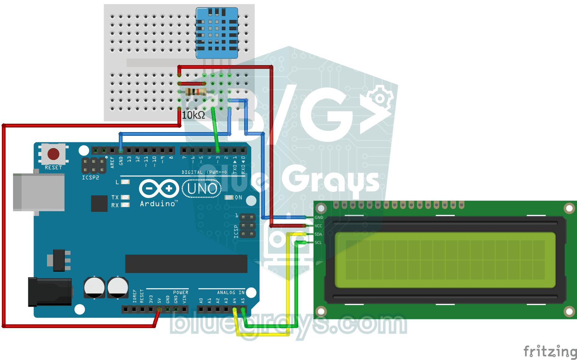
Temperature and Humidity with DHT11
How warm is your room, and is the air humid or dry? The DHT11 sensor measures temperature and humidity, and the Arduino writes the values on a two-line LCD screen, refreshing every couple of seconds.

ESP32 LED Fade with PWM
Smoothly changing the brightness of the LED from 0 to max, from max to 0. We control PWM with analogWrite() as in Arduino - the same syntax as ESP32 Arduino Core 3.0+ works without problems. Pin definition + pinMode + analogWrite is enough.
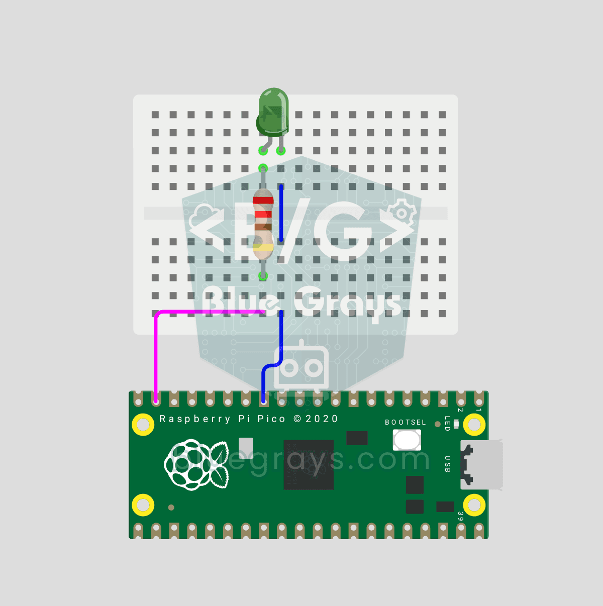
Raspberry Pi Pico PWM LED Fade (Breathing Effect)
The LED doesn't just blink anymore, it breathes! With the Raspberry Pi Pico's PWM (Pulse Width Modulation), the LED's brightness slowly rises and then slowly fades, a calm "breathing" effect like a sleeping laptop's light. You'll learn the machine.PWM class, the 16-bit brightness value from 0–65535 with duty_u16() and the PWM frequency.

ESP32 LED Brightness Control with a Potentiometer (Analog → PWM)
In this project, we control the brightness of an LED analogically using a potentiometer. The ESP32's ADC pin reads the 0-3.3V voltage from the potentiometer, and this value is then converted into a PWM (Pulse Width Modulation) signal and sent to the LED. As a result, as you turn the potentiometer, the LED gradually brightens and dims. With Arduino Core 3.0+, analogWrite() can be used directly; on the ESP32-S2/S3, the ADC resolution is fixed at 12-bit.
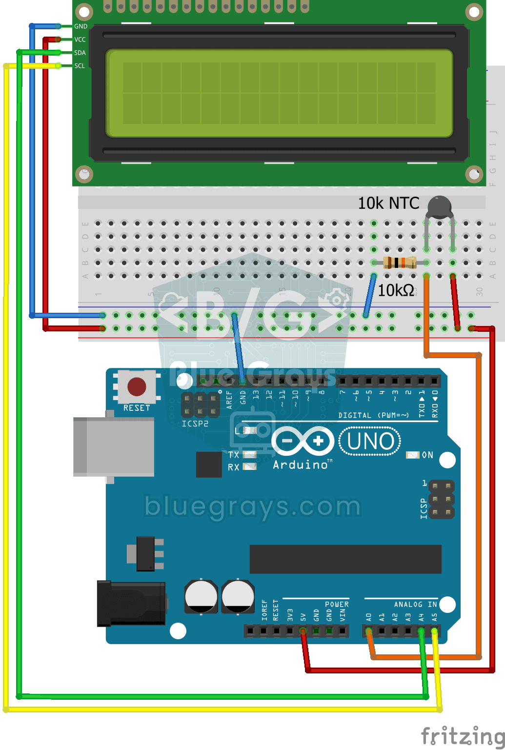
Temperature Measurement with NTC and 2x16 Lcd Display
Measure the temperature around you with a sensor that looks like a tiny bead. This part, called an NTC, lets electricity through more easily as it warms up; the Arduino reads that change, turns it…

ESP32 DHT22 Temperature and Humidity (with LCD Display)
This project measures ambient temperature and humidity using a DHT22 sensor and displays the data in real time on a 16x2 I2C LCD. Data is read from the sensor using the one-wire protocol via the Adafruit DHT library. This project serves as the foundation for IoT weather stations, smart home automation, or environmental monitoring systems in greenhouses. Communication with the DHT22 is established via the ESP32's GPIO 4 pin.
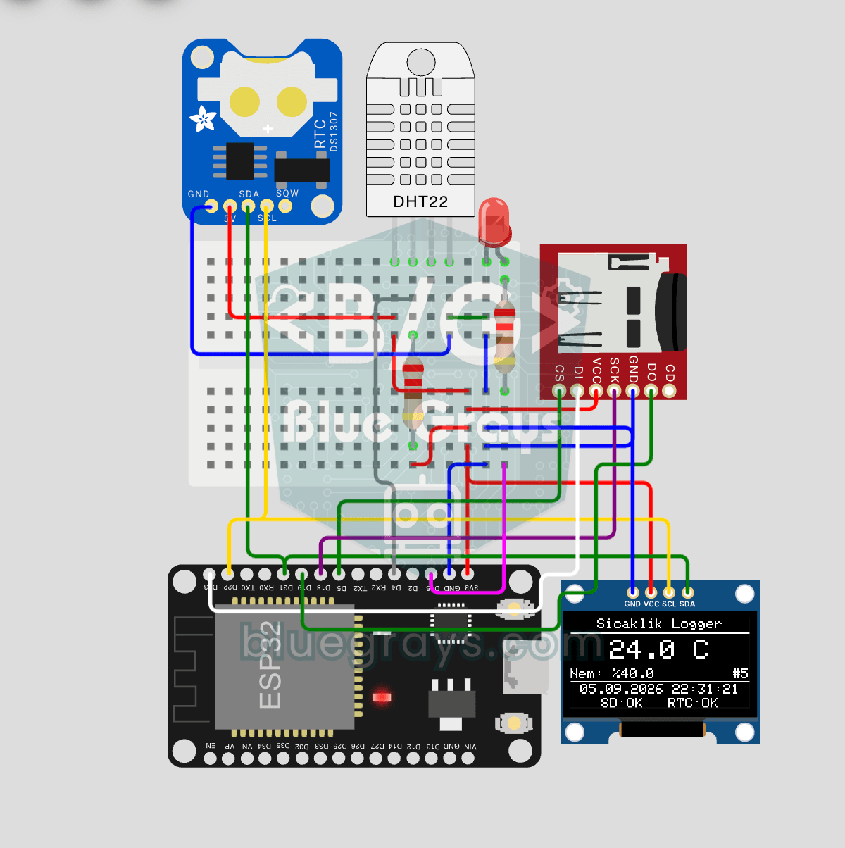
ESP32 Temperature Data Logger (DHT22 + DS1307 RTC + microSD + OLED)
Build a timed temperature and humidity logger with the ESP32! A DHT22 sensor reads temperature and humidity once a minute, and each reading is saved to a microSD card in CSV format with a real-time stamp from the DS1307 RTC module. The OLED display shows the latest temperature, humidity, timestamp and total number of records live, in large text.

Smart Irrigation Station
A gardener that waters your plants on its own, so they don't dry out while you're on vacation.