
Peltier Module with Arduino: TEC1-12706 Cooling and Heating
How do you use a TEC1-12706 Peltier module with Arduino? Hot and cold sides, heatsink, 6 A current, MOSFET and H-bridge control, DS18B20 thermostat code.

A Peltier module is a thin thermoelectric device: when current flows through it, one face gets cold and the other gets hot. Controlled with an Arduino, it lets you build a mini fridge, a drink cooler, an incubator or a temperature-controlled experiment chamber. The most common hobby model is the 40×40 mm TEC1-12706: it runs on 12 V, draws about 6 A, and pumps heat from one face to the other with no moving parts, gas or compressor. If you reverse the current, the cold face starts to heat up; so the same module can both cool and heat.
However, a Peltier isn't a part you can plug straight into an Arduino pin like an LED or a servo. On its own it consumes more than 60 watts, its hot face becomes dangerously hot within seconds, and it destroys itself without a large heatsink and fan. In this post you'll learn how a Peltier works, how to tell the hot face from the cold one, why a heatsink is mandatory, how to choose the right power supply, and how to drive it with a MOSFET and an H-bridge. In the end you'll build a mini cooler box with a DS18B20 temperature sensor and a thermostat box that both heats and cools.
What is a Peltier module and how does it work?
The Peltier effect was discovered by Jean Charles Peltier in 1834: when current passes through the junction of two different conductors, heat is either absorbed or released at that junction. Inside the TEC1-12706, small n-type and p-type semiconductor blocks made of bismuth telluride (Bi2Te3) are arranged between two thin ceramic plates. These blocks are connected electrically in series and thermally in parallel; as current passes through each n-p pair, the charge carriers (electrons and holes) carry heat in the same direction, from one plate to the other. As a result, the module behaves like a solid-state heat pump driven by electricity: it doesn't destroy heat, it only moves it from one face to the other.
The model name also gives you its technical summary: TEC stands for thermoelectric cooler, the first 1 means single stage, 127 is the number of n-p pairs inside, and 06 says the maximum current is about 6 A. The same family includes models such as TEC1-12704 (4 A), TEC1-12705 (5 A), TEC1-12708 (8 A) and TEC1-12710 (10 A). Because the pair count stays the same, they all run at around 12–15 V; as the current rises, so does the heat they can pump.
| Feature | TEC1-12706 value |
|---|---|
| Size | 40 × 40 × 3.8 mm |
| Nominal voltage | 12 V (Umax ≈ 15.4 V) |
| Maximum current (Imax) | ≈ 6.4 A |
| Maximum heat pumping (Qmax) | ≈ 50–60 W (at ΔT = 0) |
| Maximum temperature difference (ΔTmax) | ≈ 66 °C (hot face 25 °C, no load) |
| Internal resistance | ≈ 2 Ω (at room temperature) |
| Efficiency (COP) | Typically 0.3–0.7 in real use; drops as ΔT grows |
| Construction | 127 n-p pairs, bismuth telluride, alumina ceramic plates |
| Wires | Red (+), black (−) |
Hot face and cold face: which is which?
A Peltier has two wires: when the red wire goes to positive and the black wire to negative, one face gets cold and the other gets hot. When you reverse the polarity, the faces swap. Some manufacturers print the label on the hot face and some on the cold face, so don't trust the label. The safest method is this: put the module on the table, connect red to the positive and black to the negative of a 5 V 3 A adapter or a bench supply for no more than 1–2 seconds, and touch both faces with your finger. Mark the face that cooled with a pen. If you leave it connected longer, a module without a heatsink heats up quickly.
The key to understanding a Peltier is ΔT, the temperature difference between the two faces. The module doesn't bring the cold face to an absolute temperature; it brings it a certain number of degrees below the hot face. The catalogue's ΔTmax of about 66 °C is the best value measured when no heat at all is drawn from the cold face; under real load, that is when pulling heat out of a box, the difference falls to 15–30 °C. If the hot face rises to 50 °C, the cold face stays only around 20–30 °C; if you can keep the hot face at 30 °C, the cold face can drop below 0 °C. In short, how well you cool the hot side determines the performance of the cold side.
Why are a heatsink and fan mandatory?
While moving heat, a Peltier also consumes electricity, and all of that energy turns into heat. So the heat that must be dumped from the hot face is the heat drawn from the cold face plus the electrical power: Q_hot = Q_cold + V × I. A module running at 12 V and 5.5 A consumes about 66 W of electricity; if it draws 20 W from the cold face, 86 W must be dumped from the hot face. If you want to keep the hot face at most 15 °C above a 25 °C room, that is at 40 °C, the heatsink's thermal resistance must be 15 / 86 ≈ 0.17 °C/W; only a fan-cooled CPU heatsink can achieve that. A small aluminium heatsink with a thermal resistance of 3 °C/W would, on paper, climb above 250 °C at the same heat; in practice, the solder inside melts and the ceramic cracks before the module gets there.
- Thermal paste: Apply a thin, even layer to both faces; a thick layer doesn't improve heat transfer, it makes it worse.
- Hot side: Use a fan-cooled CPU heatsink or a water-cooling block; the fan must always spin while the Peltier is running.
- Cold side: A small aluminium heatsink inside the box and a 40–60 mm fan stir the air and cool every part of the box.
- Clamping: Tighten the screws in a cross pattern and a little at a time; over-tightening on one side cracks the ceramic plate.
- Prevent thermal bridges: Fill the gap between the two heatsinks with foam or a rubber gasket, and use plastic washers so metal screws don't carry the heat back.
- Insulation: Use a polystyrene or foam box; a thin plastic box lets the heat the Peltier removes leak straight back in from outside.
Current requirement and choosing a power supply
The TEC1-12706's internal resistance is about 2 Ω. If you calculate I = V / R with Ohm's law, you see it draws about 5.7 A at 12 V at first; as a temperature difference builds up between the two faces, the Seebeck voltage the module generates itself lowers the current a little, but it stays around 5 A. That means roughly 60–70 W; when you do an electrical power calculation, also add the 0.2–0.5 A drawn by the fans. A switching adapter of at least 12 V 10 A or the 12 V rail of an old computer (ATX) power supply is suitable. USB, the Arduino's 5V pin or a 9 V battery can never supply this current; for details see the Arduino power supply post. An interesting point: a Peltier is most efficient not at full current but at about 50–70% of its maximum current. That's because the heat it pumps rises in proportion to current, while the resistive loss (I²R) inside it grows with the square of the current.
| Supply voltage | Approx. current | Electrical power | Use |
|---|---|---|---|
| 5 V | 2.4 A | 12 W | Face test, light cooling, highest efficiency |
| 9 V | 4.3 A | 39 W | Balanced efficiency and cooling |
| 12 V | 5.7 A | 69 W | Nominal operation, strongest cooling |
| 15.4 V (Umax) | 6.4 A | ≈ 99 W | Limit value, don't use continuously |
Wiring: driving a Peltier with a MOSFET and an H-bridge
If you'll use the Peltier only for cooling or only for heating, a single N-channel MOSFET is enough. The MOSFET goes between the Peltier's negative lead and ground (low-side switching): the red wire goes to +12 V, the black wire to the MOSFET's drain and the source pin to GND. You must choose a logic-level MOSFET that turns fully on with the Arduino Uno's 5 V pins; the IRLZ44N has about 0.025 Ω resistance at 5 V gate voltage and dissipates 6² × 0.025 ≈ 0.9 W at 6 A, so a small heatsink is enough. The popular IRF520 modules, on the other hand, don't turn fully on at 5 V; they get hot and limit the current. Put a 100 Ω series resistor on the gate and a 10 kΩ pull-down resistor between gate and source, and always join the Arduino GND to the adapter's negative (common GND). You'll find MOSFET selection in detail in the using a MOSFET with Arduino post. On 3.3 V boards such as the ESP32 and Pico, prefer a lower-threshold MOSFET such as the IRLB8721.
If you want both heating and cooling, you need to reverse the direction of the current; the way to do that is an H-bridge. The L298N you know from robot projects isn't suitable for a Peltier, because it can only supply 2 A continuous per channel and has a voltage drop of more than 2 V. Instead, use the BTS7960 (IBT-2) H-bridge module, which can handle up to 43 A: PWM on the RPWM pin makes current flow in one direction, and PWM on the LPWM pin makes it flow in the opposite direction. To compare different drivers, take a look at the motor driver comparison post. Reversing polarity with a mechanical relay is also possible, but with frequent switching the contacts wear out and you can't adjust power.
| Connection | Arduino Uno (MOSFET) | ESP32 (BTS7960) | Pico (MOSFET) |
|---|---|---|---|
| Box DS18B20 DATA (4.7 kΩ pull-up) | D2 | GPIO 4 | GP16 |
| Heatsink DS18B20 DATA (4.7 kΩ pull-up) | D3 | — | — |
| MOSFET gate (via 100 Ω) | D9 | — | GP15 |
| BTS7960 RPWM (cooling) | — | GPIO 25 | — |
| BTS7960 LPWM (heating) | — | GPIO 26 | — |
| BTS7960 R_EN + L_EN | — | GPIO 27 | — |
| BTS7960 VCC (logic) | — | 3V3 | — |
| Sensor VCC | 5V | 3V3 | 3V3 (pin 36) |
| GND | GND + 12 V adapter (−) | GND + 12 V adapter (−) | GND + 12 V adapter (−) |
Step by step: a mini cooler box (Arduino + MOSFET)
- Prepare an insulated box (polystyrene or foam, 1–3 litres); cut a 40×40 mm window in its lid for the Peltier.
- Find the Peltier's cold face with the 1–2 second 5 V test and mark it with a pen.
- Apply a thin layer of thermal paste to the hot face; place the fan-cooled CPU heatsink outside the box, and the small heatsink and fan on the cold face so they stay inside the box. Tighten the screws evenly in a cross pattern and fill the gap in between with foam.
- Connect the red wire to the adapter's positive, the black wire to the IRLZ44N's drain and the source pin to the adapter's negative. Connect both fans directly to 12 V so they always spin while the system is on.
- Connect Arduino pin D9 to the gate through a 100 Ω resistor, put a 10 kΩ resistor between gate and source, and join the Arduino GND to the adapter's negative.
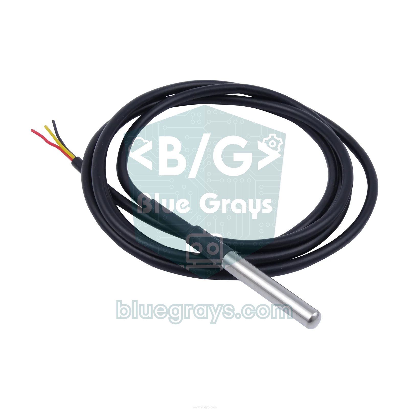
- Connect the two DS18B20 sensors: take the data lines to pins D2 (inside the box) and D3 (hot heatsink), and add a 4.7 kΩ pull-up resistor between 5V and data on each.
- Install the OneWire and DallasTemperature libraries from the Library Manager, upload the code and open the Serial Monitor at 9600 baud to watch the temperatures.
1#include <OneWire.h>
2#include <DallasTemperature.h>
3
4const int BOX_SENSOR_PIN = 2;     // kutu içi DS18B20 / DS18B20 inside the box
5const int HOT_SENSOR_PIN = 3;     // sıcak soğutucu DS18B20 / DS18B20 on the hot-side heatsink
6const int MOSFET_PIN     = 9;     // IRLZ44N gate (100 ohm üzerinden / via 100 ohm)
7
8const float TARGET_C    = 15.0;   // hedef kutu sıcaklığı / target box temperature
9const float BAND_C      = 3.0;    // bu farkta tam güç / full power at this difference
10const float HOT_LIMIT_C = 60.0;   // sıcak yüz koruma sınırı / hot-side protection limit
11const int   MAX_DUTY    = 204;    // %80 güç sınırı / 80% power limit
12
13OneWire boxWire(BOX_SENSOR_PIN);
14OneWire hotWire(HOT_SENSOR_PIN);
15DallasTemperature boxSensor(&boxWire);
16DallasTemperature hotSensor(&hotWire);
17
18void setup() {
19  Serial.begin(9600);
20  pinMode(MOSFET_PIN, OUTPUT);
21  analogWrite(MOSFET_PIN, 0);
22  // Timer1 bölücü 8: pin 9/10 PWM ~3.9 kHz / Timer1 prescaler 8: pin 9/10 PWM ~3.9 kHz
23  TCCR1B = (TCCR1B & 0b11111000) | 0x02;
24  boxSensor.begin();
25  hotSensor.begin();
26}
27
28void loop() {
29  boxSensor.requestTemperatures();
30  hotSensor.requestTemperatures();
31  float tBox = boxSensor.getTempCByIndex(0);
32  float tHot = hotSensor.getTempCByIndex(0);
33
34  int duty = 0;
35  if (tBox == DEVICE_DISCONNECTED_C || tHot == DEVICE_DISCONNECTED_C) {
36    duty = 0;                                   // sensör yoksa kapat / switch off if a sensor is missing
37    Serial.println(F("Sensor hatasi / Sensor error"));
38  } else if (tHot >= HOT_LIMIT_C) {
39    duty = 0;                                   // aşırı ısınma koruması / overheat protection
40    Serial.println(F("Sicak yuz cok sicak / Hot side too hot"));
41  } else {
42    float err = tBox - TARGET_C;                // pozitif = kutu fazla sıcak / positive = box too warm
43    if (err <= 0) duty = 0;
44    else if (err >= BAND_C) duty = MAX_DUTY;
45    else duty = (int)(err / BAND_C * MAX_DUTY); // oransal güç / proportional power
46  }
47  analogWrite(MOSFET_PIN, duty);
48
49  Serial.print(F("Kutu/Box: "));
50  Serial.print(tBox, 1);
51  Serial.print(F(" C  Sicak/Hot: "));
52  Serial.print(tHot, 1);
53  Serial.print(F(" C  PWM: "));
54  Serial.println(duty);
55  delay(1000);
56}| Code line | What it does |
|---|---|
| TCCR1B = (TCCR1B & 0b11111000) | 0x02 | Sets the Timer1 prescaler to 8; PWM on pin 9 rises from 490 Hz to about 3.9 kHz. |
| DEVICE_DISCONNECTED_C | Catches the -127 reading when the sensor wire is broken and switches the Peltier off. |
| HOT_LIMIT_C = 60.0 | If the fan stops or the heatsink is inadequate, the hot face is protected at 60 °C. |
| err / BAND_C * MAX_DUTY | Increases power proportionally while the box is 0–3 °C above target; gives 80% power at 3 °C and above. |
| MAX_DUTY = 204 | Limits power to 80%; improves efficiency and extends the life of the module and adapter. |
Heating and cooling with the ESP32: BTS7960 H-bridge
By driving the Peltier in both directions through a BTS7960 with an ESP32, you can build a thermostat box that holds a constant temperature regardless of the room temperature: it cools if the box is above the target and heats if it's below. In heating mode the Peltier is especially efficient; the face looking into the box receives both the heat it pumps from outside and the electricity it consumes, so with 40 W of electricity it can deliver more than 40 W of heat. Connect the 12 V adapter to the BTS7960's B+ and B− inputs and the Peltier to the M+ and M− outputs; if you connect the module's logic VCC pin to the ESP32's 3V3 pin, it reads the 3.3 V signals without trouble. The code automatically selects the different LEDC functions in ESP32 Arduino core 2.x and 3.x.
1#include <OneWire.h>
2#include <DallasTemperature.h>
3
4const int SENSOR_PIN   = 4;       // DS18B20 DATA
5const int RPWM_PIN     = 25;      // BTS7960 RPWM: soğutma yönü / cooling direction
6const int LPWM_PIN     = 26;      // BTS7960 LPWM: ısıtma yönü / heating direction
7const int EN_PIN       = 27;      // BTS7960 R_EN + L_EN
8const int RPWM_CH      = 0;       // core 2.x LEDC kanalı / core 2.x LEDC channel
9const int LPWM_CH      = 1;
10const int PWM_FREQ     = 20000;   // 20 kHz, duyulmaz / inaudible
11const int PWM_RES      = 8;       // 0-255
12const int PELTIER_DUTY = 200;     // ~%78 güç / ~78% power
13
14const float TARGET_C = 25.0;      // hedef sıcaklık / target temperature
15const float HYST_C   = 1.0;       // histerezis / hysteresis
16const unsigned long REVERSE_WAIT_MS = 30000;  // yön değiştirme beklemesi / reversal wait
17
18OneWire oneWire(SENSOR_PIN);
19DallasTemperature sensors(&oneWire);
20
21int currentMode = 0;              // 0 kapalı, 1 soğutma, -1 ısıtma / 0 off, 1 cool, -1 heat
22int lastDir = 0;
23unsigned long lastChange = 0;
24
25void pwmBegin(int pin, int ch) {
26#if ESP_ARDUINO_VERSION_MAJOR >= 3
27  ledcAttach(pin, PWM_FREQ, PWM_RES);   // core 3.x
28#else
29  ledcSetup(ch, PWM_FREQ, PWM_RES);     // core 2.x
30  ledcAttachPin(pin, ch);
31#endif
32}
33
34void pwmWrite(int pin, int ch, int duty) {
35#if ESP_ARDUINO_VERSION_MAJOR >= 3
36  ledcWrite(pin, duty);                 // core 3.x: pin ile / by pin
37#else
38  ledcWrite(ch, duty);                  // core 2.x: kanal ile / by channel
39#endif
40}
41
42void applyMode(int m) {
43  if (m == 1) {
44    pwmWrite(LPWM_PIN, LPWM_CH, 0);
45    pwmWrite(RPWM_PIN, RPWM_CH, PELTIER_DUTY);
46  } else if (m == -1) {
47    pwmWrite(RPWM_PIN, RPWM_CH, 0);
48    pwmWrite(LPWM_PIN, LPWM_CH, PELTIER_DUTY);
49  } else {
50    pwmWrite(RPWM_PIN, RPWM_CH, 0);
51    pwmWrite(LPWM_PIN, LPWM_CH, 0);
52  }
53}
54
55void setup() {
56  Serial.begin(115200);
57  pwmBegin(RPWM_PIN, RPWM_CH);
58  pwmBegin(LPWM_PIN, LPWM_CH);
59  applyMode(0);                         // önce iki yön de kapalı / both directions off first
60  pinMode(EN_PIN, OUTPUT);
61  digitalWrite(EN_PIN, HIGH);           // sürücüyü etkinleştir / enable the driver
62  sensors.begin();
63}
64
65void loop() {
66  sensors.requestTemperatures();
67  float t = sensors.getTempCByIndex(0);
68
69  int want = currentMode;
70  if (t == DEVICE_DISCONNECTED_C) {
71    want = 0;                           // sensör yok: kapat / no sensor: switch off
72  } else if (currentMode == 0) {
73    if (t > TARGET_C + HYST_C) want = 1;
74    else if (t < TARGET_C - HYST_C) want = -1;
75  } else if (currentMode == 1 && t <= TARGET_C) {
76    want = 0;
77  } else if (currentMode == -1 && t >= TARGET_C) {
78    want = 0;
79  }
80
81  if (want != currentMode) {
82    bool reversing = (want != 0 && lastDir != 0 && want != lastDir);
83    if (!reversing || millis() - lastChange >= REVERSE_WAIT_MS) {
84      currentMode = want;
85      lastChange = millis();
86      if (currentMode != 0) lastDir = currentMode;
87      applyMode(currentMode);
88    }
89  }
90
91  Serial.printf("T: %.2f C  mod/mode: %d\n", t, currentMode);
92  delay(1000);
93}
There are two important safety rules in the code. The first is hysteresis: cooling starts when the box goes 1 °C above the target and stops when it reaches the target; heating works the opposite way. That way the system doesn't constantly switch on and off around the target. The second is the reversal wait: an abrupt switch from cooling to heating suddenly heats a face that was ice-cold a second ago and causes thermal shock in the ceramic; for that reason the code stays off for at least 30 seconds before switching to the opposite direction. Which direction cools depends on your wiring; if the box heats up on the first try, swap the M+ and M− wires. For more precise control, see the Arduino thermostat and PID control posts.
Peltier control with Raspberry Pi Pico and MicroPython
On the Raspberry Pi Pico, thanks to the onewire and ds18x20 modules that come built into MicroPython, you can read a DS18B20 without installing any extra library. The code below does the same proportional cooling as the Arduino example: PWM goes from pin GP15 to the MOSFET's gate; the DS18B20 is connected to GP16 and pulled up to 3V3 with 4.7 kΩ. The Pico's PWM has 16-bit resolution; duty_u16() takes a value from 0 to 65535, and 52000 corresponds to about 80% power. Don't forget to use a low-threshold MOSFET again for the 3.3 V gate signal. If you're new to MicroPython, the MicroPython basics post is a good start.
1from machine import Pin, PWM
2import onewire, ds18x20, time
3
4TARGET_C = 15.0          # hedef sıcaklık / target temperature
5BAND_C = 3.0             # bu farkta tam güç / full power at this difference
6MAX_DUTY = 52000         # ~%80 güç / ~80% power
7
8pwm = PWM(Pin(15))       # MOSFET gate
9pwm.freq(5000)           # 5 kHz PWM
10pwm.duty_u16(0)
11
12ow = onewire.OneWire(Pin(16))   # DS18B20 DATA (4.7k pull-up)
13ds = ds18x20.DS18X20(ow)
14roms = ds.scan()
15if not roms:
16    raise RuntimeError("DS18B20 bulunamadi / not found")
17
18while True:
19    ds.convert_temp()
20    time.sleep_ms(750)               # dönüşüm süresi / conversion time
21    t = ds.read_temp(roms[0])
22    err = t - TARGET_C               # pozitif = fazla sıcak / positive = too warm
23    if err <= 0:
24        duty = 0
25    elif err >= BAND_C:
26        duty = MAX_DUTY
27    else:
28        duty = int(err / BAND_C * MAX_DUTY)   # oransal güç / proportional power
29    pwm.duty_u16(duty)
30    print("T: {:.2f} C  guc/power: {}%".format(t, duty * 100 // 65535))
31    time.sleep(1)
Project ideas with a Peltier
- Single-can drink cooler: Make a desktop soda cooler with a polystyrene box, one TEC1-12706 and a DS18B20; show the temperature on a small display.
- Incubator or yoghurt maker: Use the Peltier in the heating direction to hold the 37–43 °C range steady; the thermostat logic is the same here too.
- Filament drying box: Remove moisture from 3D printer filament for hours at 45–50 °C.
- Mini dehumidifier: Bring the cold face below the dew point to collect moisture from the air drop by drop and measure the water collected.
- Thermoelectric generator experiment: Put one face of the Peltier on hot water and the other on ice; measure the voltage produced by the Seebeck effect with an Arduino voltmeter.
- Fan speed by temperature: Speed up the hot-side fan according to the heatsink temperature; details are in the Arduino fan control post.
- Science fair project: A constant-temperature seed germination chamber or an enzyme experiment box stands out among the science competition project ideas.
Common mistakes and how to fix them
| Mistake | Symptom | Fix |
|---|---|---|
| Running without a heatsink | The module overheats in seconds, you smell burning, the ceramic cracks | Fit a fan-cooled CPU heatsink on the hot face and keep the fan always running |
| The cold face doesn't cool | Both faces heat up, the box heats up | Hot-side cooling is inadequate or the polarity is reversed; use a bigger heatsink, check the wires |
| Powering it from the Arduino | The Arduino resets, the USB port shuts down | Power the Peltier from a separate 12 V 10 A adapter |
| Driving it with an L298N | The driver gets very hot, current stays around 2 A | Use a high-current H-bridge such as the BTS7960 |
| Using an IRF520 module | The MOSFET gets hot, the Peltier works weakly | Use a logic-level MOSFET such as the IRLZ44N |
| No common GND | The MOSFET doesn't turn on or works randomly | Join the Arduino GND to the adapter's negative |
| Thick thermal paste | ΔT is much lower than expected | Apply a thin, even layer |
| Tightening the screws on one side | The module cracked, draws no current or shorts | Tighten in a cross pattern and a little at a time |
| Reversing abruptly | The module fails quickly | Wait at least 30 seconds before reversing |
A Peltier module is a silent heat pump with no moving parts that can work in both directions; when controlled safely with the right heatsink, an adequate power supply and a MOSFET or BTS7960, it adds a whole new dimension to Arduino projects. If you can't decide on a sensor, the temperature sensor comparison post will help. In the BlueGrays app you'll find DHT11, NTC, DHT22 and temperature logger projects as well as PWM power control examples with step-by-step circuit diagrams and code, and you can easily adapt the measurement and control logic in those projects to your own Peltier box.
Frequently asked questions
How cold can a Peltier module get?
The TEC1-12706's maximum temperature difference in the catalogue is about 66 °C, but that value is measured when no heat is drawn from the cold face. In a real cooler box with good insulation and a fan-cooled CPU heatsink, reaching 10–15 °C below ambient is a realistic goal. The cooler you keep the hot face, the colder the cold side gets.
Can a Peltier be connected directly to an Arduino?
No. The TEC1-12706 draws about 5–6 A at 12 V, while an Arduino pin can supply at most 20–40 mA. You should power the Peltier from a separate 12 V adapter and use the Arduino only to control a logic-level MOSFET or an H-bridge such as the BTS7960.
Can you make a fridge with a Peltier?
You can make a small drink cooler or picnic box, but a Peltier's efficiency (COP) is usually between 0.3 and 0.7; compressor fridges use several times less energy for the same cooling. Making a freezer with a single TEC1-12706 isn't practical; making ice takes multi-stage modules and very strong cooling.
How many watts does the TEC1-12706 draw?
At 12 V it draws about 5–5.7 A, that is 60–70 W of electrical power; at the maximum voltage of 15.4 V this approaches 100 W. If you choose a power supply of at least 12 V 10 A including the fans, you leave a safe margin.
Which side of a Peltier module gets cold?
It depends on the direction of the current: when the red wire goes to positive and the black wire to negative, one of the faces gets cold, and when you reverse the polarity the roles swap. Since the face the label is printed on varies from manufacturer to manufacturer, the safest way is to connect the module to 5 V for 1–2 seconds and mark the one that cools by touching the faces.
Can a Peltier module run on a battery?
It works, but not for long. A pack of three 18650 cells, 11.1 V and 2500 mAh, lasts only 25–30 minutes at a 5 A draw, and the cells must be a high-discharge type that can supply that current. For portable projects, it makes more sense to run the Peltier at low power or to use a car's 12 V cigarette lighter socket.
Projects to build after reading this
See all projects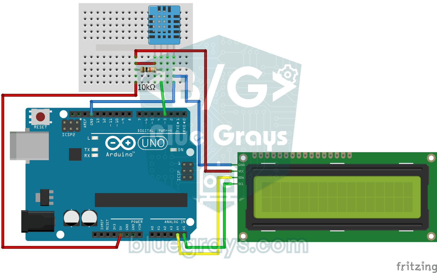
Temperature and Humidity with DHT11
How warm is your room, and is the air humid or dry? The DHT11 sensor measures temperature and humidity, and the Arduino writes the values on a two-line LCD screen, refreshing every couple of seconds.
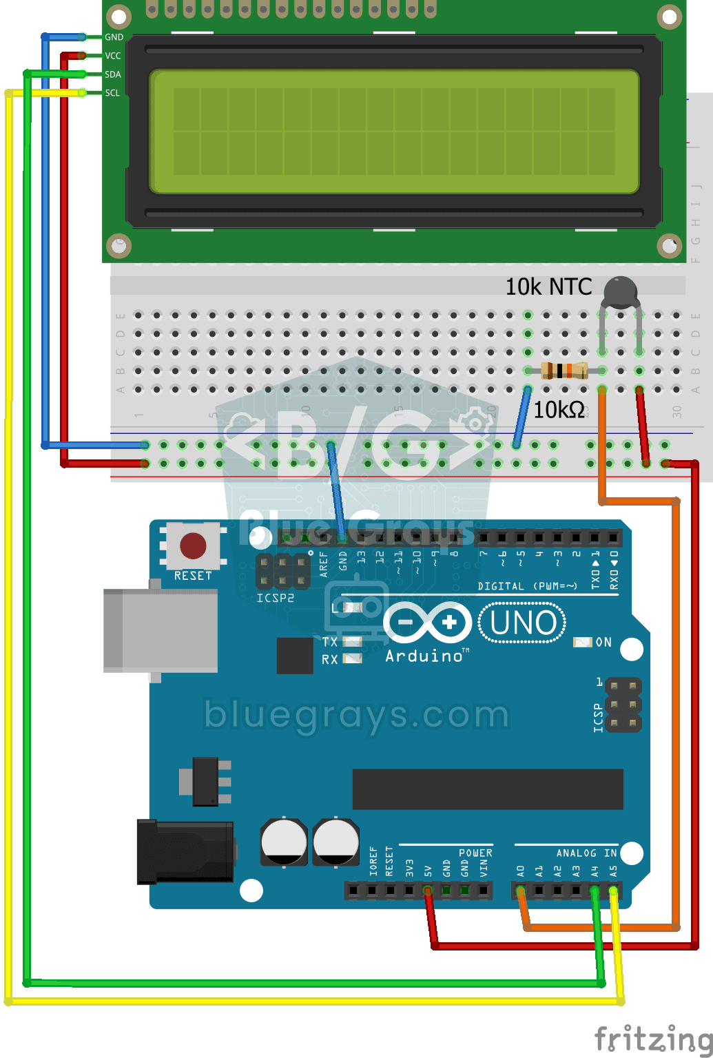
Temperature Measurement with NTC and 2x16 Lcd Display
Measure the temperature around you with a sensor that looks like a tiny bead. This part, called an NTC, lets electricity through more easily as it warms up; the Arduino reads that change, turns it…

ESP32 DHT22 Temperature and Humidity (with LCD Display)
This project measures ambient temperature and humidity using a DHT22 sensor and displays the data in real time on a 16x2 I2C LCD. Data is read from the sensor using the one-wire protocol via the Adafruit DHT library. This project serves as the foundation for IoT weather stations, smart home automation, or environmental monitoring systems in greenhouses. Communication with the DHT22 is established via the ESP32's GPIO 4 pin.
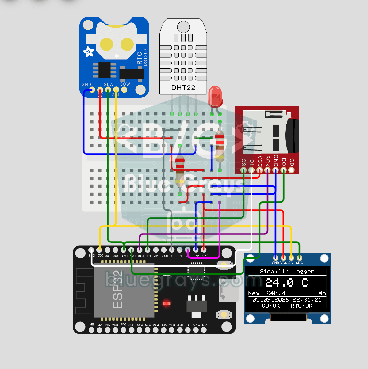
ESP32 Temperature Data Logger (DHT22 + DS1307 RTC + microSD + OLED)
Build a timed temperature and humidity logger with the ESP32! A DHT22 sensor reads temperature and humidity once a minute, and each reading is saved to a microSD card in CSV format with a real-time stamp from the DS1307 RTC module. The OLED display shows the latest temperature, humidity, timestamp and total number of records live, in large text.

ESP32 LED Brightness Control with a Potentiometer (Analog → PWM)
In this project, we control the brightness of an LED analogically using a potentiometer. The ESP32's ADC pin reads the 0-3.3V voltage from the potentiometer, and this value is then converted into a PWM (Pulse Width Modulation) signal and sent to the LED. As a result, as you turn the potentiometer, the LED gradually brightens and dims. With Arduino Core 3.0+, analogWrite() can be used directly; on the ESP32-S2/S3, the ADC resolution is fixed at 12-bit.

ESP32 LED Fade with PWM
Smoothly changing the brightness of the LED from 0 to max, from max to 0. We control PWM with analogWrite() as in Arduino - the same syntax as ESP32 Arduino Core 3.0+ works without problems. Pin definition + pinMode + analogWrite is enough.
Raspberry Pi Pico PWM LED Fade (Breathing Effect)
The LED doesn't just blink anymore, it breathes! With the Raspberry Pi Pico's PWM (Pulse Width Modulation), the LED's brightness slowly rises and then slowly fades, a calm "breathing" effect like a sleeping laptop's light. You'll learn the machine.PWM class, the 16-bit brightness value from 0–65535 with duty_u16() and the PWM frequency.

Smart Irrigation Station
A gardener that waters your plants on its own, so they don't dry out while you're on vacation.