
PID Controller Arduino: Tune Kp, Ki, Kd with Code Examples
What is a PID controller and how does it work? P, I and D terms, the Arduino PID library, tuning Kp/Ki/Kd, plus temperature control and line follower robot code.

PID control is a feedback method that keeps a system at the value you want by continuously calculating the difference between the measured value and the target (the error) and adjusting the output accordingly. In Arduino projects it's used to hold a heater at exactly 45 °C, spin a motor at a constant speed, or drive a line follower robot right along the middle of the line. The name comes from its three parts: the Proportional (P) term looks at the present error, the Integral (I) term at error accumulated in the past, and the Derivative (D) term at how fast the error is changing. The weighted sum of the three sets the PWM value sent to the motor or heater.
The formulas look scary at first, but the logic of PID is a lot like what you already do without thinking while driving a car. In this post you'll first see why simple on-off control oscillates, then get to know the three terms through intuitive examples. After that you'll build temperature control with the Arduino PID library using an NTC and a MOSFET, learn to tune Kp, Ki and Kd step by step, and drive a line follower robot with a PID written without a library. Finally, we'll run the same algorithm on the ESP32 and on the Raspberry Pi Pico with MicroPython.
Why isn't on-off control enough?
The simplest control method is on-off control: if the temperature is below the target, turn the heater on at full power; if it's above, turn it off. The boiler thermostat at home and an aquarium heater work largely this way. The problem is that when the heater switches off, the heat stored in it keeps flowing into the surroundings, so the temperature overshoots the target by a few degrees. When it starts cooling, the heater switches on again, but the temperature drops below the target until it warms up. The result is a sawtooth that constantly rises and falls around the target. To smooth this out, a gap (hysteresis) is left between two thresholds; the relay clicks less often but the amplitude of the swing grows. On a 3D printer bed, an incubator or a motor that must spin at a constant speed, where you need to stay within ±0.5 °C, this isn't enough. PID, on the other hand, produces a gradual output between full power and zero, and reduces the power ahead of time as the system approaches the target.
| Method | How it decides | Pros | Cons | Typical use |
|---|---|---|---|---|
| On-off | Full power below the target, off above it | Very simple, can even be done with a relay | Constant oscillation and overshoot, relay wear | Boiler thermostat, aquarium heater |
| P | Output proportional to the error | Smooth response, easy to tune | Leaves a steady-state error | Simple position and level control |
| PI | Proportional + accumulated error | Removes the steady-state error | More overshoot, integral windup | Temperature, flow and motor speed control |
| PID | Proportional + accumulated error + rate of change | Fast, low overshoot, precise | Hard to tune, sensitive to noise | 3D printer, drone, balancing robot, line follower robot |
What is PID control and how does it work?
In every loop, PID first calculates the error: error = target value (setpoint) − measured value (input). Then it evaluates this error in three different ways and adds them up: output = Kp·e + Ki·∫e·dt + Kd·de/dt. Here Kp, Ki and Kd are coefficients you set; they determine how much each term contributes to the output. On a microcontroller, the integral is calculated by adding the product of the error and the sample time to a running sum at every sample, and the derivative by dividing the difference between the last two measurements by the sample time. That's why, for PID to work properly, it's important to take measurements at fixed intervals, for example every 10 ms or every 500 ms. Think of following a lane in a car: the farther you are from the lane, the more you turn the wheel (P); if a crosswind keeps pushing you, you learn to hold the wheel slightly turned (I); and as you approach the lane quickly, you ease off the turn early (D).
| Term | What it looks at | Intuitive analogy | If too high |
|---|---|---|---|
| P (Proportional) | The present error | The farther you are from the lane, the more you turn the wheel | Fast oscillation, jitter |
| I (Integral) | Error accumulated over time | With a crosswind, you learn to hold the wheel slightly turned | Slow, wide oscillation, large overshoot |
| D (Derivative) | The rate of change of the error | As you approach the lane quickly, you ease off the turn early | Overreaction to noise, jittery output |
Proportional (P) term: a response proportional to the error
The proportional term adjusts the output in direct proportion to the size of the error. With Kp = 20, a 3 °C error produces 60 PWM units and a 1 °C error produces 20 units; as you approach the target, the power drops automatically. As you increase Kp, the system responds faster, but beyond a certain point it starts to overshoot the target and swing back, in other words oscillate. Control with P alone has a significant weakness: steady-state error. Say that holding the heater at 45 °C needs a continuous 80 units of power to offset the heat escaping to the surroundings. With only a P term, those 80 units can be produced only while there's an error: 80 / 20 = 4 °C. So the system settles at around 41 °C and never reaches the target. Increasing Kp shrinks this gap but also increases oscillation.
Integral (I) term: erases the steady-state error
The integral term adds up the error over time. Even a small error, if it persists for a long time, makes the total grow and the output rises slowly until the error reaches zero. In the example above, the integral term now supplies the required 80 units of power, the P term falls to zero, and the temperature settles at exactly 45 °C. The larger Ki is, the faster the steady-state error closes; if it's too large, the system makes slow, wide oscillations. A well-known trap of the integral is a situation called integral windup: if the heater is already at full power and can't reach the target, the integral keeps growing for nothing, and when the target is reached, this accumulated value keeps the temperature above the target for a long time. The fix is to clamp the integral with the output limits; the Arduino PID library does this automatically with SetOutputLimits.
Derivative (D) term: brakes as you approach the target
The derivative term looks at how fast the error is changing and provides a kind of prediction. If the temperature is approaching the target quickly, the error shrinks quickly; the D term contributes in the opposite direction to this change, cuts the power early and reduces overshoot. The same happens in a robot: a robot turning quickly toward the line eases its turn before crossing it. The weakness of the D term is its sensitivity to noise. If an analog sensor's reading jumps by a few units with every measurement, the derivative sees these small jumps as large changes and the output jitters. That's why you need to average or filter the sensor reading; see the sensor data filtering post for details. Also, good PID implementations take the derivative from the measurement rather than the error; that way, when you suddenly change the target, there's no sudden jump in the output (derivative kick).
Example 1: Temperature control with the Arduino PID library
In the first example we'll hold a small heater (a 12 V heating pad or a power resistor) at 45 °C. We'll measure the temperature with a voltage divider made of a 10 kΩ NTC thermistor and a 10 kΩ fixed resistor, and drive the heater with PWM through a logic-level N-channel MOSFET (e.g. IRLZ44N). In the Arduino IDE, open the Library Manager, search for PID and install Brett Beauregard's PID library (PID_v1). This library handles details such as sample time management, output limiting, protection against integral windup and taking the derivative from the measurement for you. For the details of the MOSFET connection, take a look at the Using a MOSFET with Arduino post.
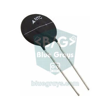
| Connection | Arduino Uno | ESP32 | Raspberry Pi Pico |
|---|---|---|---|
| Divider supply (top end of the 10 kΩ fixed resistor) | 5V | 3V3 | 3V3 |
| Junction of the NTC and the fixed resistor | A0 | GPIO 34 | GP26 (ADC0) |
| Bottom end of the NTC | GND | GND | GND |
| MOSFET gate (through 220 Ω, with 10 kΩ to GND) | D9 | GPIO 25 | GP15 |
| MOSFET source | GND | GND | GND |
| Heater | Between +12 V and the MOSFET drain | Between +12 V and the MOSFET drain | Between +12 V and the MOSFET drain |
1#include <PID_v1.h>
2
3const int NTC_PIN = A0;        // NTC bölücü orta noktası / NTC divider midpoint
4const int HEATER_PIN = 9;      // MOSFET gate (PWM) / MOSFET gate (PWM)
5
6const float R_FIXED = 10000.0; // sabit direnç / fixed resistor
7const float R0 = 10000.0;      // NTC'nin 25 °C direnci / NTC resistance at 25 °C
8const float T0 = 298.15;       // 25 °C kelvin cinsinden / 25 °C in kelvin
9const float BETA = 3950.0;     // NTC Beta katsayısı / NTC beta coefficient
10
11double setpoint = 45.0;        // hedef sıcaklık / target temperature
12double input = 0;              // ölçülen sıcaklık / measured temperature
13double output = 0;             // ısıtıcı gücü 0-255 / heater power 0-255
14
15double Kp = 20.0, Ki = 0.5, Kd = 10.0;   // başlangıç değerleri / starting values
16PID heaterPID(&input, &output, &setpoint, Kp, Ki, Kd, DIRECT);
17
18float readTemperature() {
19  long sum = 0;
20  for (int i = 0; i < 16; i++) {
21    sum += analogRead(NTC_PIN);            // 16 ölçüm ortalaması / average of 16 readings
22  }
23  float adc = sum / 16.0;
24  adc = constrain(adc, 1.0, 1022.0);       // sıfıra bölmeyi önle / avoid division by zero
25  float r = R_FIXED * adc / (1023.0 - adc);                // NTC direnci / NTC resistance
26  float kelvin = 1.0 / (1.0 / T0 + log(r / R0) / BETA);    // Beta denklemi / beta equation
27  return kelvin - 273.15;
28}
29
30void setup() {
31  Serial.begin(115200);
32  pinMode(HEATER_PIN, OUTPUT);
33  input = readTemperature();
34  heaterPID.SetOutputLimits(0, 255);       // analogWrite aralığı / analogWrite range
35  heaterPID.SetSampleTime(500);            // 500 ms'de bir hesapla / compute every 500 ms
36  heaterPID.SetMode(AUTOMATIC);            // PID'yi başlat / start the PID
37}
38
39void loop() {
40  input = readTemperature();
41  if (heaterPID.Compute()) {               // yeni çıkış hazırsa / if a new output is ready
42    analogWrite(HEATER_PIN, (int)output);
43    Serial.print(setpoint);                // Seri Çizici için / for the Serial Plotter
44    Serial.print(' ');
45    Serial.print(input);
46    Serial.print(' ');
47    Serial.println(output / 255.0 * 100.0); // güç yüzdesi / power percent
48  }
49}
In the code, the readTemperature() function reduces noise by averaging 16 readings, calculates the NTC resistance from the divider formula (R = 10 kΩ · adc / (1023 − adc)) and converts it to degrees Celsius with the Beta equation (B = 3950). SetOutputLimits(0, 255) keeps the output in the analogWrite range and stops the integral from running past these limits. SetSampleTime(500) makes the PID calculate every half second; since heat is a slowly changing quantity, this is enough. Compute() returns true only when it's time to sample, so you shouldn't use delay() inside loop(). If you open the three values written to the serial port in the Serial Plotter in the Tools menu, you'll see the target, the temperature and the heater power as a percentage on the same graph and watch the effect of your tuning instantly. In a cooling system (e.g. fan cooling), the output needs to increase as the temperature rises; in that case use REVERSE instead of DIRECT.
How to tune Kp, Ki and Kd: step by step
- Set Ki and Kd to zero, start Kp at a small value (e.g. 2) and open the Serial Plotter.
- Double Kp step by step; stop when the system quickly approaches the target and starts oscillating continuously around it. Use about half of that value as Kp.
- Add Kd: start from a small value and increase it until the overshoot and oscillation die out. If the output starts to jitter or the motor starts to buzz, Kd is too high or the sensor is noisy.
- Add Ki last: increase it slowly until the steady-state error closes in a reasonable time. If the temperature draws slow, wide waves around the target, reduce Ki.
- Test with a disturbance: change the target by 5 °C, blow on the heater or give the robot a light push by hand; watch how long the system takes to recover and with how much overshoot.
- If you like, use the Ziegler-Nichols method as a starting point: with P alone, measure the gain that starts sustained oscillation (Ku) and the oscillation period (Tu, in seconds); start with Kp = 0.6·Ku, Ki = 1.2·Ku / Tu, Kd = 0.075·Ku·Tu and fine-tune by hand.
| When you increase the coefficient | Rise time | Overshoot | Settling time | Steady-state error |
|---|---|---|---|---|
| Kp | Gets shorter | Increases | Changes little | Decreases |
| Ki | Gets shorter | Increases | Gets longer | Eliminated |
| Kd | Changes little | Decreases | Gets shorter | In theory no effect |
Example 2: PID in a line follower robot
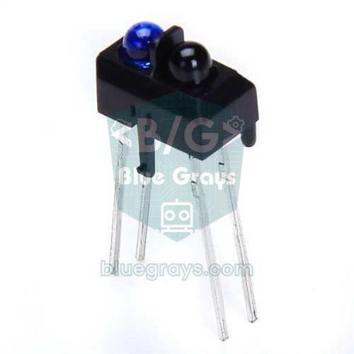
In a line follower robot, the goal is for the line to stay exactly in the middle of the robot. By taking a weighted average of the readings from three analog TCRT5000 sensors placed left, center and right, we turn the line's position into a number between 0 (far left) and 2000 (far right); 1000 is dead center. The error is the difference between the position and 1000. The correction produced by the PID is added to the left motor's speed and subtracted from the right motor's speed, so the robot turns smoothly toward the line. A robot using simple on-off logic (turn left if the line is on the left, turn right if it's on the right) wobbles and moves slowly, while a PID robot goes along the same track much faster and with a smooth path. In this example we write the PID from scratch without a library; the motors are controlled with an L298N driver.
1const int SENSOR_PINS[3] = {A0, A1, A2};   // sol, orta, sağ / left, center, right
2
3const int ENA = 5, IN1 = 7, IN2 = 8;       // sol motor / left motor
4const int ENB = 6, IN3 = 9, IN4 = 10;      // sağ motor / right motor
5
6const int BASE_SPEED = 150;                // düz giderken hız / cruising speed
7float Kp = 0.1, Ki = 0.0, Kd = 0.004;      // robota göre ayarla / tune for your robot
8
9float lastError = 0;
10float integral = 0;
11int lastPosition = 1000;
12unsigned long lastTime = 0;
13
14int readPosition() {
15  long sum = 0, weighted = 0;
16  int maxValue = 0;
17  for (int i = 0; i < 3; i++) {
18    int v = analogRead(SENSOR_PINS[i]);    // siyah çizgi = yüksek değer / black line = high value
19    weighted += (long)v * i * 1000L;
20    sum += v;
21    if (v > maxValue) maxValue = v;
22  }
23  if (maxValue > 500) {                    // çizgi görülüyor / line is visible
24    lastPosition = weighted / sum;         // 0 sol, 1000 orta, 2000 sağ / 0 left, 1000 center, 2000 right
25  }
26  return lastPosition;                     // çizgi kaybolursa son konum / last position if line is lost
27}
28
29void setMotor(int en, int inA, int inB, int speed) {
30  speed = constrain(speed, -255, 255);
31  if (speed >= 0) {
32    digitalWrite(inA, HIGH);               // ileri / forward
33    digitalWrite(inB, LOW);
34  } else {
35    digitalWrite(inA, LOW);                // geri / backward
36    digitalWrite(inB, HIGH);
37    speed = -speed;
38  }
39  analogWrite(en, speed);
40}
41
42void setup() {
43  int pins[] = {ENA, IN1, IN2, ENB, IN3, IN4};
44  for (int i = 0; i < 6; i++) {
45    pinMode(pins[i], OUTPUT);
46  }
47  lastTime = millis();
48}
49
50void loop() {
51  unsigned long now = millis();
52  if (now - lastTime < 10) return;         // 10 ms örnekleme / 10 ms sampling
53  float dt = (now - lastTime) / 1000.0;    // saniye cinsinden / in seconds
54  lastTime = now;
55
56  float error = readPosition() - 1000;     // negatif = çizgi solda / negative = line on the left
57  integral += error * dt;
58  integral = constrain(integral, -500.0, 500.0);   // windup sınırı / windup limit
59  float derivative = (error - lastError) / dt;
60  lastError = error;
61
62  float correction = Kp * error + Ki * integral + Kd * derivative;
63  setMotor(ENA, IN1, IN2, (int)(BASE_SPEED + correction));
64  setMotor(ENB, IN3, IN4, (int)(BASE_SPEED - correction));
65}
The sensors are connected to A0, A1 and A2, the L298N's ENA and ENB pins to the D5 and D6 PWM pins, and the IN1–IN4 pins to D7, D8, D9 and D10; don't forget to remove the jumpers on ENA and ENB. The loop runs every 10 ms using millis(); that way dt stays constant and the coefficients behave consistently. You can find why we use millis() instead of delay() in the millis and delay post. If the error is negative, the line is on the left: the correction becomes negative, the left motor slows down, the right motor speeds up and the robot turns left. Since the error is at most 1000, Kp = 0.1 means a correction of about 100 PWM units at the largest error. Because the derivative is calculated per second, it's normal for Kd to look as small as 0.004. In a line follower, Ki is usually kept at zero or very small; the integral is useful only if the robot drifts constantly in one direction (e.g. one motor is weaker than the other). If your own sensors read high on a white surface and low on the black line, invert the reading as 1023 − v.
PID with the ESP32 and Raspberry Pi Pico
Since the PID_v1 library is written in pure C++, it works on the ESP32 as is; all you need to do is connect the NTC to GPIO 34 and the MOSFET gate to GPIO 25. The differences are in the hardware: the ESP32's ADC is 12-bit (0–4095) and is nonlinear near the ends of its range; keeping the measured voltage between 0.3 and 2.8 V improves the result. For PWM, the LEDC peripheral is used instead of analogWrite, and since this API changed with core 3.x, the code includes a version check. Thanks to being fast and dual-core, the ESP32 can receive a new target temperature from a web page at the same time while running the PID loop.
1#include <PID_v1.h>
2
3const int NTC_PIN = 34;        // ADC1 girişi / ADC1 input
4const int HEATER_PIN = 25;     // MOSFET gate / MOSFET gate
5const int PWM_FREQ = 1000;     // 1 kHz PWM / 1 kHz PWM
6const int PWM_BITS = 8;        // 0-255 çözünürlük / 0-255 resolution
7
8double setpoint = 45.0, input = 0, output = 0;
9PID heaterPID(&input, &output, &setpoint, 20.0, 0.5, 10.0, DIRECT);
10
11float readTemperature() {
12  long sum = 0;
13  for (int i = 0; i < 16; i++) {
14    sum += analogRead(NTC_PIN);            // 12 bit: 0-4095 / 12-bit: 0-4095
15  }
16  double adc = constrain(sum / 16.0, 1.0, 4094.0);
17  double r = 10000.0 * adc / (4095.0 - adc);                     // NTC direnci / NTC resistance
18  return 1.0 / (1.0 / 298.15 + log(r / 10000.0) / 3950.0) - 273.15;
19}
20
21void setup() {
22  Serial.begin(115200);
23  analogReadResolution(12);
24#if ESP_ARDUINO_VERSION_MAJOR >= 3
25  ledcAttach(HEATER_PIN, PWM_FREQ, PWM_BITS);   // çekirdek 3.x / core 3.x
26#else
27  ledcSetup(0, PWM_FREQ, PWM_BITS);             // çekirdek 2.x, kanal 0 / core 2.x, channel 0
28  ledcAttachPin(HEATER_PIN, 0);
29#endif
30  input = readTemperature();
31  heaterPID.SetOutputLimits(0, 255);
32  heaterPID.SetSampleTime(500);
33  heaterPID.SetMode(AUTOMATIC);
34}
35
36void loop() {
37  input = readTemperature();
38  if (heaterPID.Compute()) {
39#if ESP_ARDUINO_VERSION_MAJOR >= 3
40    ledcWrite(HEATER_PIN, (uint32_t)output);    // pin ile yaz / write by pin
41#else
42    ledcWrite(0, (uint32_t)output);             // kanal ile yaz / write by channel
43#endif
44    Serial.printf("%.1f %.2f %.0f\n", setpoint, input, output / 255.0 * 100.0);
45  }
46}
There's no ready-made PID module for MicroPython on the Raspberry Pi Pico, so we write the algorithm as a small class. This class imitates three important things the Arduino library does: it keeps the integral within the output limits (anti-windup), takes the derivative from the measurement, and accounts for the sample time (dt). The Pico's ADC returns values in the 0–65535 range with read_u16(); the PID output is calculated in the 0–255 range and multiplied by 257 to scale it to 16 bits for duty_u16(). That way you can use the Kp, Ki and Kd values you found on the Arduino on the Pico too. The NTC divider is connected to GP26 and the MOSFET gate to GP15. If you're new to MicroPython, you can start with the MicroPython basics post.
1from machine import ADC, Pin, PWM
2import math
3import time
4
5ntc = ADC(26)                     # GP26 = ADC0, NTC bölücüsü / NTC divider
6heater = PWM(Pin(15))             # MOSFET gate / MOSFET gate
7heater.freq(1000)                 # 1 kHz PWM / 1 kHz PWM
8
9R_FIXED = 10000                   # sabit direnç / fixed resistor
10R0 = 10000                        # NTC'nin 25 °C direnci / NTC resistance at 25 °C
11T0 = 298.15                       # 25 °C kelvin cinsinden / 25 °C in kelvin
12BETA = 3950                       # Beta katsayısı / beta coefficient
13SETPOINT = 45.0                   # hedef sıcaklık / target temperature
14
15def read_temp():
16    total = 0
17    for _ in range(16):
18        total += ntc.read_u16()   # 16 ölçüm ortalaması / average of 16 readings
19    adc = min(max(total / 16, 1), 65534)
20    r = R_FIXED * adc / (65535 - adc)
21    return 1 / (1 / T0 + math.log(r / R0) / BETA) - 273.15
22
23class PID:
24    def __init__(self, kp, ki, kd, out_min, out_max):
25        self.kp, self.ki, self.kd = kp, ki, kd
26        self.out_min, self.out_max = out_min, out_max
27        self.i_term = 0
28        self.last_input = None
29
30    def compute(self, setpoint, measurement, dt):
31        error = setpoint - measurement
32        self.i_term += self.ki * error * dt                               # biriken hata / accumulated error
33        self.i_term = min(max(self.i_term, self.out_min), self.out_max)  # integral sınırı / anti-windup
34        if self.last_input is None:
35            d_input = 0
36        else:
37            d_input = (measurement - self.last_input) / dt                # ölçümden türev / derivative on measurement
38        self.last_input = measurement
39        out = self.kp * error + self.i_term - self.kd * d_input
40        return min(max(out, self.out_min), self.out_max)
41
42pid = PID(20, 0.5, 10, 0, 255)    # Arduino ile aynı katsayılar / same gains as Arduino
43last = time.ticks_ms()
44
45while True:
46    now = time.ticks_ms()
47    if time.ticks_diff(now, last) >= 500:                                 # 500 ms örnekleme / 500 ms sampling
48        dt = time.ticks_diff(now, last) / 1000
49        last = now
50        temp = read_temp()
51        power = pid.compute(SETPOINT, temp, dt)
52        heater.duty_u16(int(power * 257))                                 # 0-255 -> 0-65535
53        print(SETPOINT, round(temp, 2), round(power))
PID control project ideas
- Precision thermostat: In an Arduino thermostat project, use PID instead of on-off to hold an incubator or a fermentation cabinet within ±0.3 °C.
- Fan speed by temperature: In a fan control project, drive the fan with a REVERSE-direction PID to get quiet, steady cooling.
- Fast line follower robot: Add 5 sensors and PID to a line follower robot project to reach racing speed.
- Self-balancing robot: Measure the tilt angle with an MPU-6050 and keep a two-wheeled robot upright; it's one of the most instructive applications of PID.
- Solar tracker: In a solar tracker project, use the difference between two LDRs as the error and turn the panel smoothly.
- Soldering station or mini oven: Measure high temperatures with a MAX6675 thermocouple and drive the heater with PID.
- Constant-speed motor: Hold the speed of an encoder-equipped geared DC motor at the target even when the load changes.
Common mistakes and how to fix them
| Symptom | Likely cause | Fix |
|---|---|---|
| The system oscillates constantly and quickly around the target | Kp is too high or Kd is insufficient | Reduce Kp by 30–50% and increase Kd a little |
| It never reaches the target and stays a few degrees below | Ki is zero or too small | Increase Ki slowly; check that the heater's power is sufficient |
| Large, long-lasting overshoot at the end of warm-up | Integral windup | Limit the output with SetOutputLimits, clamp the integral, reduce Ki |
| The output jitters, the motor buzzes | Noisy sensor and high Kd | Average or filter the measurement, reduce Kd |
| The output rises as the temperature rises | Control direction is reversed | Use REVERSE for cooling or flip the sign of the error |
| The same coefficients work well sometimes and badly other times | Irregular sampling, delay() in the loop | Use a fixed dt with millis(), avoid delay() |
| The heater is always at full power but the temperature doesn't rise | Insufficient hardware (power, insulation, MOSFET) | PID can't make up for missing hardware; check the power and connections |
PID control combines the measure-compare-correct loop with three simple ideas, and it's used everywhere from hobby projects to industrial ovens. First see the limits of on-off control, then start with P, brake with D and close the steady-state error with I; the graph in the Serial Plotter will guide you at every step. In the BlueGrays app you can look step by step, with circuit diagrams and code, at projects that use the parts in this post, such as temperature measurement with an NTC, surface detection with a TCRT5000, an L298N robot car and PWM control with a potentiometer, and start adding PID to your own project from there.
Frequently asked questions
What is PID control and what is it used for?
PID control is a feedback method that continuously calculates the error to keep a measured value at a target value and adjusts the output accordingly. The proportional term reacts to the present error, the integral term to accumulated error, and the derivative term to the rate of change of the error. In temperature, motor speed, position and balance control, it gives much more stable and precise results than on-off control.
How do you find Kp, Ki and Kd values?
The most practical way is manual tuning: set Ki and Kd to zero, increase Kp until the system oscillates and then halve it, add Kd to suppress overshoot, and add Ki last to close the steady-state error. The Ziegler-Nichols method gives a good starting point, but fine-tuning is almost always done by hand. The values are specific to the system; coefficients copied from another project may not work in your circuit.
What is the difference between PID and on-off control?
On-off control makes the output either fully on or fully off, so constant oscillation and overshoot occur around the target. PID adjusts the output gradually, reduces the power ahead of time as it nears the target and erases the steady-state error with the integral term. On-off is simpler and cheaper; PID is more precise but needs tuning.
Which Arduino PID library should I use and how do I install it?
The most common one is Brett Beauregard's PID library (PID_v1). In the Arduino IDE, search for "PID" in the Library Manager to install it, then include the PID_v1.h header in your code. The library handles sample time, output limiting and protection against integral windup by itself.
What is integral windup and how do you prevent it?
Integral windup is when the error keeps accumulating in the integral while the output is already at its limit (e.g. the heater is at full power). When the target is reached, this accumulated value makes the system overshoot the target for a long time. To prevent it, you need to keep the integral within the output limits; in the Arduino PID library, SetOutputLimits does this automatically.
Can you do PID control with a relay?
Yes, using time proportioning: for example, in a 5-second window, if the PID output is 40 percent, the relay is kept on for 2 seconds and off for 3 seconds. Because mechanical relays wear out quickly with frequent switching, a solid-state relay (SSR) is better suited for this job. For slow-responding systems like heaters, this method works as well as PWM.
Projects to build after reading this
See all projects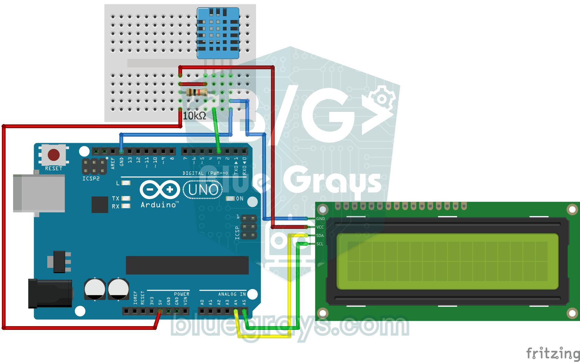
Temperature and Humidity with DHT11
How warm is your room, and is the air humid or dry? The DHT11 sensor measures temperature and humidity, and the Arduino writes the values on a two-line LCD screen, refreshing every couple of seconds.
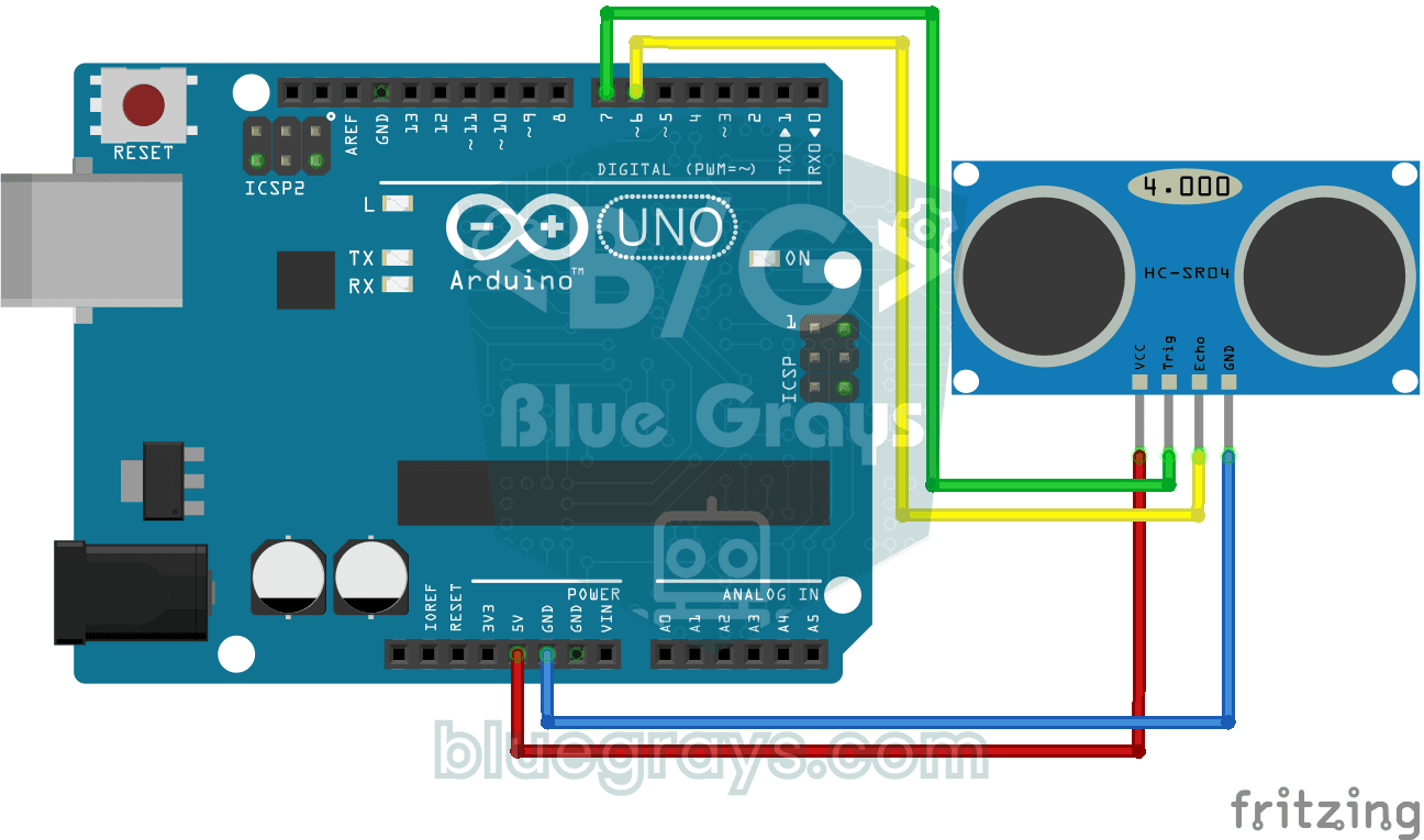
HC-SR04 Distance Measurement (Serial Display)
The HC-SR04 sensor works just like a bat finding its way in the dark: it sends out a sound you cannot hear, listens for the echo and measures how far away the object in front of it is.
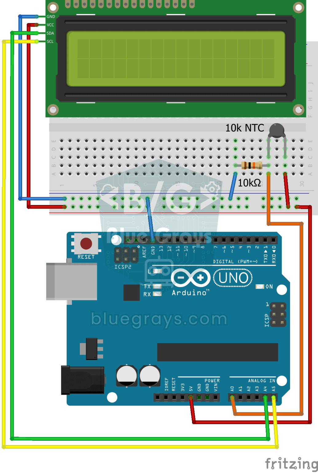
Temperature Measurement with NTC and 2x16 Lcd Display
Measure the temperature around you with a sensor that looks like a tiny bead. This part, called an NTC, lets electricity through more easily as it warms up; the Arduino reads that change, turns it…

TCRT5000 Black and White Surface Detection
With the little sensor that acts as the eye of line-following robots, you can tell whether the floor is black or white.

Reading Reflection (Proximity) with TCRT5000
With a small sensor that sends out invisible light and measures how much bounces back, you can detect the surface in front of it.

Obstacle Avoidance Robot
How about building a smart vehicle that finds its own way? The Obstacle Avoidance Robot constantly scans its surroundings thanks to the ultrasonic sensor in front of it.

Bluetooth Controlled Car with L298N
Turn your phone into a remote and drive your own robot car. The Arduino receives commands from a remote-control app on your phone through a Bluetooth module and spins the wheels with a motor driver…

ESP32 LED Brightness Control with a Potentiometer (Analog → PWM)
In this project, we control the brightness of an LED analogically using a potentiometer. The ESP32's ADC pin reads the 0-3.3V voltage from the potentiometer, and this value is then converted into a PWM (Pulse Width Modulation) signal and sent to the LED. As a result, as you turn the potentiometer, the LED gradually brightens and dims. With Arduino Core 3.0+, analogWrite() can be used directly; on the ESP32-S2/S3, the ADC resolution is fixed at 12-bit.