
Arduino Nano Pinout: Pin Diagram, A6/A7, Power and Old Bootloader
Arduino Nano pinout in one guide: D0–D13, A0–A7 (A6/A7 analog only), PWM pins, VIN/5V/3V3, CH340 driver, Old Bootloader and a Uno-to-Nano pin map.
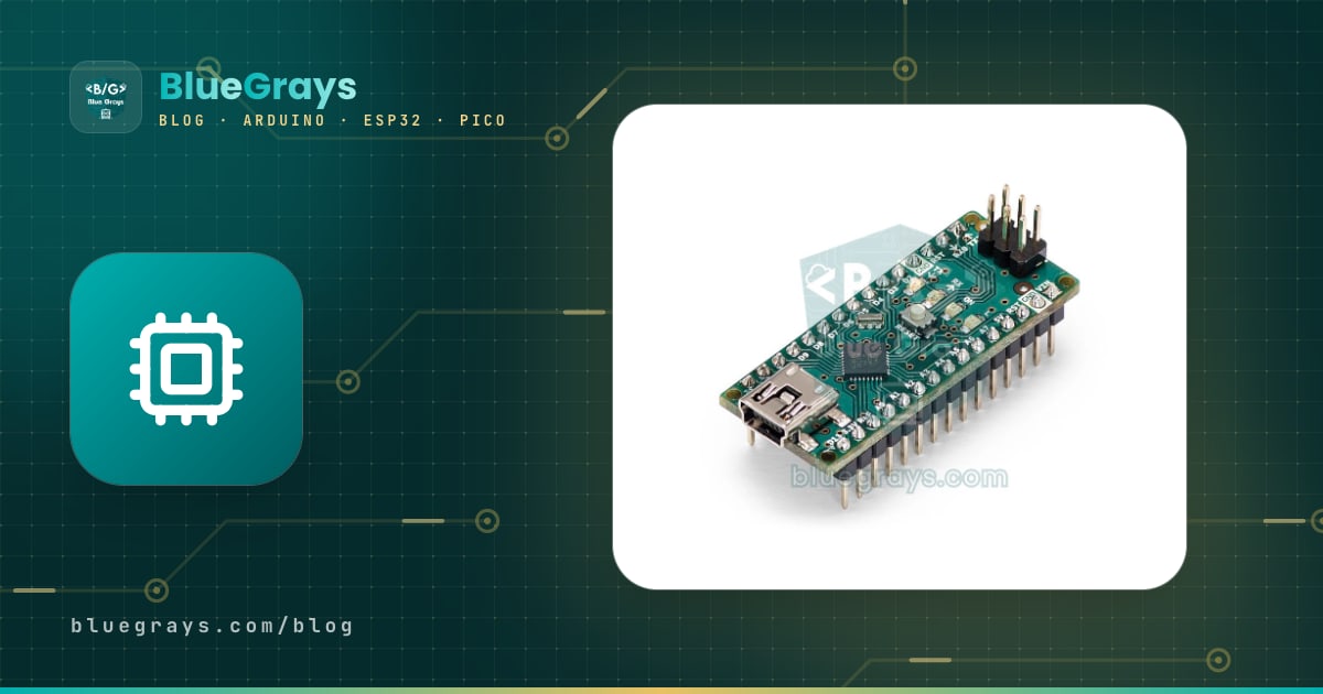
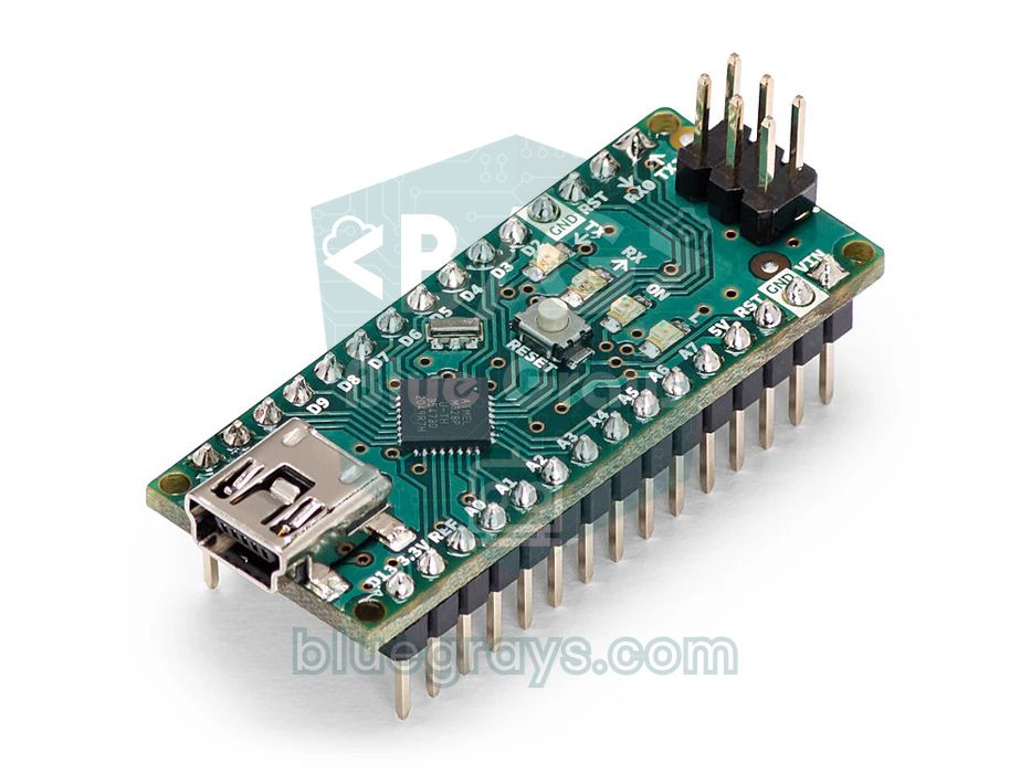
The Arduino Nano pinout consists of 30 pins lined up along the two long edges of a 45 × 18 mm board: 14 digital input/output pins (D0–D13), 6 of which can output PWM (~3, 5, 6, 9, 10, 11), 8 analog inputs (A0–A7), and the power and control pins: VIN, 5V, 3V3, AREF, two GND and two RST. Because the Nano uses the same ATmega328P processor as the Arduino Uno, the pin numbers and functions are the same too: a sketch written for the Uno runs without any changes, apart from selecting the Nano in the board menu.
Still, a few important details set the Nano apart from the Uno, and they're exactly where beginners get stuck: A6 and A7 are analog-only, there's no DC jack, the 3V3 pin supplies very little current, clone boards handle USB with a CH340 chip, and you often need to select ATmega328P (Old Bootloader) to upload code. In this guide you'll get to know every pin, learn how to place the Nano on a breadboard correctly, see the Uno-to-Nano pin mapping, and find out how the Nano Every and Nano ESP32 differ from the classic Nano.
What is the Arduino Nano, and how is it different from the Uno?
The Arduino Nano packs all of the Uno's core features into a board measuring 45 × 18 mm and weighing about 7 grams. Its pins point downwards, so it plugs straight into a breadboard; that means fewer jumper wires, and once the circuit is finished it moves easily into a box or onto a permanent circuit board. Inside is the same 16 MHz ATmega328P as on the Uno, the logic level is 5 V, and the same libraries work unchanged. On the original Nano, USB-to-serial communication is handled by an FT232RL chip; almost all of the affordable clones on the market have a CH340G or CH340C on the underside of the board instead. For robot cars, wearables, remotes and any circuit that has to fit in a box, the Nano is a more practical choice than the Uno.
| Feature | Arduino Nano (V3) |
|---|---|
| Microcontroller | ATmega328P, 8-bit, 16 MHz (TQFP-32 package) |
| Logic (operating) voltage | 5 V |
| VIN input voltage | 7–12 V recommended |
| Digital input/output | 14 pins (D0–D13); 20 including A0–A5 |
| PWM output | 6 pins: D3, D5, D6, D9, D10, D11 |
| Analog input | 8 pins (A0–A7), 10-bit (0–1023) |
| Current per pin | 20 mA recommended, 40 mA absolute maximum |
| Memory | 32 KB flash (30,720 bytes usable in the IDE), 2 KB SRAM, 1 KB EEPROM |
| USB | Mini-B; FT232RL (original) or CH340 (clone) |
| Size and weight | 45 × 18 mm, about 7 g |
Arduino Nano pin diagram: which pin is where?
The Nano's 30 pins are arranged in two facing rows of 15, and the rows are 15.24 mm (0.6 in) apart. Put the board in front of you with the mini USB socket closest to you and you'll see two facing pins right next to the socket: D12 and D13. The row with D13 holds 3V3, AREF, A0–A7 and the power pins; the row with D12 holds the digital pins from D11 down to D2, followed by GND, RST, RX0 (D0) and TX1 (D1). At the end of the two rows farthest from USB, VIN and TX1 face each other, and the 2×3 ICSP header is at this end too. Around the reset button in the middle you'll find the power LED (POW or ON), the L LED connected to D13, and the TX and RX LEDs that flicker during uploads.
| Position (from USB) | Analog and power row | Digital row | Note |
|---|---|---|---|
| 1 | D13 (SCK, L LED) | D12 (MISO) | Right next to the USB socket |
| 2 | 3V3 | ~D11 (MOSI) | 3V3 supplies very little current |
| 3 | AREF | ~D10 (SS) | - |
| 4 | A0 | ~D9 | - |
| 5 | A1 | D8 | - |
| 6 | A2 | D7 | - |
| 7 | A3 | ~D6 | - |
| 8 | A4 (SDA) | ~D5 | I2C data line |
| 9 | A5 (SCL) | D4 | I2C clock line |
| 10 | A6 | ~D3 (INT1) | A6 is analog-only |
| 11 | A7 | D2 (INT0) | A7 is analog-only |
| 12 | 5V | GND | 5V and GND face each other |
| 13 | RST | RST | Both are the same reset line |
| 14 | GND | D0 (RX0) | D0 is wired to the USB-serial chip |
| 15 | VIN | D1 (TX1) | The ICSP header is at this end |
Digital pins (D0–D13), PWM and special functions
Each digital pin is set as an input or output with pinMode(); as an output, HIGH gives about 5 V and LOW gives 0 V. To avoid leaving an input floating, you can switch on the chip's internal 20–50 kΩ resistor with INPUT_PULLUP. The safe current per pin is 20 mA; a red LED with a 220 Ω resistor draws about 13 mA, and you can find the right resistor with the LED resistor calculator. Some pins have extra functions, and knowing them in advance prevents conflicts once your project grows:
| Pin | Extra function | What to watch out for |
|---|---|---|
| D0 (RX), D1 (TX) | Hardware serial port (Serial) | Wired to the USB-serial chip through 1 kΩ resistors; leave free while uploading |
| D2, D3 | External interrupts INT0, INT1 | attachInterrupt() works only on these two pins |
| ~D3, ~D11 | PWM, Timer2 (about 490 Hz) | PWM on these pins breaks while tone() is playing |
| ~D5, ~D6 | PWM, Timer0 (about 980 Hz) | Same timer as millis() and delay() |
| ~D9, ~D10 | PWM, Timer1 (about 490 Hz) | The Servo library disables PWM on these two pins |
| D10–D13 | SPI: SS, MOSI, MISO, SCK | D10 must stay an output when using SPI |
| D13 | On-board L LED | The LED and its resistor connect directly to the pin |
A small but important detail that sets the Nano apart from the Uno is on D13. On the Uno R3 the L LED is driven through an op-amp, whereas on the Nano the LED and its resistor connect directly to the pin. If you use D13 as a button input with INPUT_PULLUP, the LED pulls the pin down and you may read LOW even when the button isn't pressed; keep this pin for outputs or SPI. You'll find how PWM works and what analogWrite() values mean in What is PWM?, and interrupts in Arduino interrupts.
Analog pins A0–A7: why are A6 and A7 different?
The Nano's eight analog inputs measure voltages between 0 and 5 V with 10-bit resolution: analogRead() returns a number from 0 to 1023, and one step is about 4.9 mV. When needed, A0–A5 also work as normal digital pins (A0 = 14 … A5 = 19), and A4 and A5 double as the SDA and SCL lines of the I2C bus. A6 and A7, which the Uno doesn't have, are two extra ADC channels found on the surface-mount (TQFP) package of the ATmega328P. These two channels are connected only to the analog-to-digital converter; there's no port register, output driver or pull-up resistor behind them. That's why pinMode(), digitalRead(), digitalWrite() and INPUT_PULLUP don't work on these two pins.
A6 and A7 being analog-only may look like a drawback, but you can put it to clever use. If you connect several buttons to one analog pin through resistors of different values, each button produces a different voltage; that way you read four buttons with a single pin and keep the digital pins free for motors and displays. In the circuit, connect A6 to 5V through a 10 kΩ resistor; connect the first button directly between A6 and GND, and the other three buttons to GND through 2.2 kΩ, 4.7 kΩ and 10 kΩ resistors respectively.
1// A6'da 4 buton: 10 kΩ pull-up + farklı seri dirençler / 4 buttons on A6: 10 kΩ pull-up + different series resistors
2const byte LADDER_PIN = A6;    // yalnız analog pin / analog-only pin
3
4byte readButton() {
5  int v = analogRead(LADDER_PIN);
6  if (v < 92)  return 1;       // 0 Ω      -> yaklaşık 0 / about 0
7  if (v < 256) return 2;       // 2,2 kΩ   -> yaklaşık 184 / about 184
8  if (v < 419) return 3;       // 4,7 kΩ   -> yaklaşık 327 / about 327
9  if (v < 767) return 4;       // 10 kΩ    -> yaklaşık 512 / about 512
10  return 0;                    // basılı değil -> 1023 / not pressed -> 1023
11}
12
13void setup() {
14  Serial.begin(9600);
15}
16
17void loop() {
18  static byte lastButton = 0;
19  byte b = readButton();
20  if (b != lastButton) {
21    delay(20);                 // kontak sıçramasını bekle / wait out contact bounce
22    b = readButton();          // değeri doğrula / confirm the value
23    if (b != lastButton) {
24      lastButton = b;
25      if (b != 0) {
26        Serial.print(F("Buton / Button: "));
27        Serial.println(b);
28      }
29    }
30  }
31}| Button | Series resistor to GND | Expected analogRead | Range accepted in code |
|---|---|---|---|
| Button 1 | 0 Ω (direct) | 0 | 0–91 |
| Button 2 | 2.2 kΩ | About 184 | 92–255 |
| Button 3 | 4.7 kΩ | About 327 | 256–418 |
| Button 4 | 10 kΩ | About 512 | 419–766 |
| None | - | 1023 | 767–1023 |
The values come from the formula analogRead = 1023 × R / (10 kΩ + R), and each threshold sits exactly halfway between two neighbouring values. Because the pull-up resistor and the ADC are fed from the same 5 V rail, the readings don't change even if the supply drops to 4.7 V; this is called a ratiometric measurement. If two buttons are pressed at once, their resistors end up in parallel and the reading drops: the code sees a lower-numbered button, and pressing 3 and 4 together even reads as 2. That's why a resistor ladder suits menus where only one key is pressed at a time. You can try the divider maths with the voltage divider calculator and read more about analog readings in the ADC article.
Power pins: VIN, 5V, 3V3 and GND
| Pin | What it does | Limits and cautions |
|---|---|---|
| VIN | Powers the board with 7–12 V; the regulator drops it to 5 V | The AMS1117 on clones tolerates at most 15 V and heats up quickly at 12 V |
| 5V | The board's 5 V rail: as an output it powers sensors, as an input it accepts regulated 5 V | About 4.7 V on USB; never feed it more than 5 V from outside |
| 3V3 | 3.3 V output | Comes from the FT232RL on the original and from the CH340 on clones; very limited current |
| GND (2 pins) | Common ground | The GND of every external supply must connect here |
| RST (2 pins) | Restarts the board when pulled LOW | For an external reset button; both are the same line |
| AREF | External reference input for analog measurements | Call analogReference(EXTERNAL) before using it |
You can power the Nano in three ways. When powered over USB, the 5 V comes from the computer through a Schottky diode; the diode drops about 0.3 V, so you'll usually measure 4.6–4.8 V on the 5V pin, and the MBR0520 diode on the original board is rated for at most 500 mA. If you feed 7–12 V into the VIN pin, the regulator on the underside (an LM1117 on the original, usually an AMS1117 on clones) drops it to 5 V. The regulator turns the excess voltage into heat: the power it dissipates is (VIN − 5 V) × current, so drawing 150 mA from a 12 V input makes the small regulator burn about 1 W and get too hot to touch. That's why 7–9 V is ideal for VIN. The third way is to feed regulated 5 V into the 5V pin from outside; the regulator is then bypassed, and the diode on the USB side stops current flowing back into your computer. If you're running from a 12 V supply, using an LM2596 buck converter to make 5 V and feeding it into the 5V pin is a much cooler solution; all the powering options are covered in How to power an Arduino.
The 3V3 pin is the Nano's most misunderstood pin. On the Uno this pin comes from a separate regulator, but the classic Nano has no separate 3.3 V regulator. On the original Nano, the 3.3 V comes from a small regulator inside the FT232RL chip (50 mA at most), and according to Arduino's older documentation this output isn't available when the board isn't powered over USB. On most clones the pin is connected to the CH340's own internal regulator and is only safe for loads of a few mA. So don't power 3.3 V modules such as the nRF24L01, ESP-01 or RC522 from this pin; use a separate AMS1117-3.3 regulator fed from the 5V pin. And when connecting a 5 V Nano output to the input of a 3.3 V module, put a level shifter or a voltage divider in between.
The 5V pin sitting around 4.7 V on USB also affects analog measurements: analogRead() uses the supply voltage as its upper limit, so if you put 5.0 V into your calculation the result is off by 4–6 percent. You can work out the real supply voltage by measuring the ATmega328P's internal fixed reference of about 1.1 V. The first test sketch below does exactly that, converts all eight analog inputs to volts using the real supply voltage and blinks the L LED on D13:
1// Arduino Nano: A0-A7'yi ve gerçek besleme gerilimini oku / read A0-A7 and the real supply voltage
2const byte ANALOG_PINS[8] = {A0, A1, A2, A3, A4, A5, A6, A7};
3
4long readVccMillivolts() {
5  // Referans AVcc, ölçülen kanal dahili 1,1 V / reference AVcc, measured channel internal 1.1 V
6  ADMUX = _BV(REFS0) | _BV(MUX3) | _BV(MUX2) | _BV(MUX1);
7  delay(2);                                // referansın oturmasını bekle / let the reference settle
8  ADCSRA |= _BV(ADSC);                     // dönüşümü başlat / start the conversion
9  while (bit_is_set(ADCSRA, ADSC)) {}      // bitmesini bekle / wait until it finishes
10  unsigned int raw = ADC;                  // 10 bit sonuç / 10-bit result
11  return 1125300L / raw;                   // 1,1 V x 1023 x 1000 / 1.1 V x 1023 x 1000
12}
13
14void setup() {
15  Serial.begin(9600);
16  pinMode(LED_BUILTIN, OUTPUT);            // D13'teki L LED'i / L LED on D13
17}
18
19void loop() {
20  long vcc = readVccMillivolts();
21  analogRead(A0);                          // kanal değişti, ilk okumayı at / channel changed, discard the first reading
22  Serial.print(F("Vcc: "));
23  Serial.print(vcc);
24  Serial.print(F(" mV |"));
25  for (byte i = 0; i < 8; i++) {
26    int raw = analogRead(ANALOG_PINS[i]);  // A6 ve A7 de okunur / A6 and A7 are read too
27    Serial.print(F(" A"));
28    Serial.print(i);
29    Serial.print(F("="));
30    Serial.print(raw * (vcc / 1000.0) / 1023.0, 2);   // gerçek Vcc ile volta çevir / convert to volts using the real Vcc
31  }
32  Serial.println();
33  digitalWrite(LED_BUILTIN, !digitalRead(LED_BUILTIN));   // L LED'ini çevir / toggle the L LED
34  delay(1000);
35}
After uploading, open the Serial Monitor at 9600 baud. The Vcc value should be around 4600–4800 mV on USB and around 5000 mV when powered through VIN. Unconnected analog pins show random values; if you connect a potentiometer to A0 and turn it, you'll see the value change smoothly between 0 and Vcc. The internal reference can vary by ±10% from chip to chip; for a more accurate result, measure the 5V pin with a multimeter and multiply the 1125300 constant in the code by the ratio your measured value / the value the code shows. Because this sketch uses ATmega328P registers directly, it won't work on the Nano Every or Nano ESP32.
Mini USB, CH340 and driver installation
The classic Nano has a Mini-B USB socket; the Micro-USB or USB-C cables used for phones won't fit it. Some newer clones have Micro-USB or USB-C sockets, but most are still mini USB. The most common reason the board doesn't show up in the port list at all is a charge-only cable with no data wires: the power LED lights up, but the computer doesn't see the board. If the cable is fine, turn the board over and look at the chip near the USB socket. If it says FT232RL, you have an original Nano and its driver is usually already in the operating system; if it says CH340G or CH340C, you have a clone.
Windows 10 and 11 often install the CH340 driver themselves through Windows Update, and the board shows up in Device Manager with a name like USB-SERIAL CH340 (COM3). If you see a USB2.0-Serial with a yellow exclamation mark under Other devices, install the CH341SER driver from the chip maker WCH, then unplug the board and plug it back in. Current macOS versions include the driver; the port appears as /dev/cu.usbserial-…, and installing old drivers on top can cause conflicts. On Linux the driver is built into the kernel; if the port disappears as soon as you plug the board in on Ubuntu 22.04 or later, the screen reader package brltty is grabbing the CH340, and if you don't use it you can remove it with sudo apt remove brltty. All port and driver problems are covered in Arduino won't upload, and the differences between USB-serial chips in USB-to-TTL converters.
Uploading code: ATmega328P or Old Bootloader?
- In the Arduino IDE, select Tools > Board > Arduino AVR Boards > Arduino Nano.
- Plug the board in and pick the newly appeared port under Tools > Port (such as COM3 on Windows or /dev/cu.usbserial-… on macOS).
- Under Tools > Processor, first try uploading the Blink example with the ATmega328P option.
- If the output repeats programmer is not responding or not in sync for ten attempts, set Processor to ATmega328P (Old Bootloader) and upload again.
- If it still fails, try another USB port, remove any wires from D0 and D1, and check that the L LED blinks quickly when you press the reset button.
- Note down which option worked; other Nanos from the same seller will most likely need the same setting.
The reason for this confusion is a change made in 2018. Arduino replaced the Nano's old 2 KB bootloader (ATmegaBOOT) with the 512-byte Optiboot used on the Uno. Optiboot receives code at 115200 baud, while the old bootloader expects 57600 baud; when the speeds don't match, the board seems not to respond at all. Because clone makers kept shipping boards with the old bootloader for years, the IDE offers both options, and picking the wrong one does the board no harm. If you like, you can use a second Arduino as an ArduinoISP to burn the new bootloader onto the Nano: uploads get faster and the old bootloader's endless reset loop after a watchdog reset goes away too.
| Processor option | Bootloader | Upload speed | Space for code |
|---|---|---|---|
| ATmega328P | Optiboot (since 2018) | 115200 baud | 30,720 bytes |
| ATmega328P (Old Bootloader) | ATmegaBOOT (old) | 57600 baud | 30,720 bytes |
| ATmega168 | ATmegaBOOT (old) | 19200 baud | 14,336 bytes |
Breadboard placement and soldering
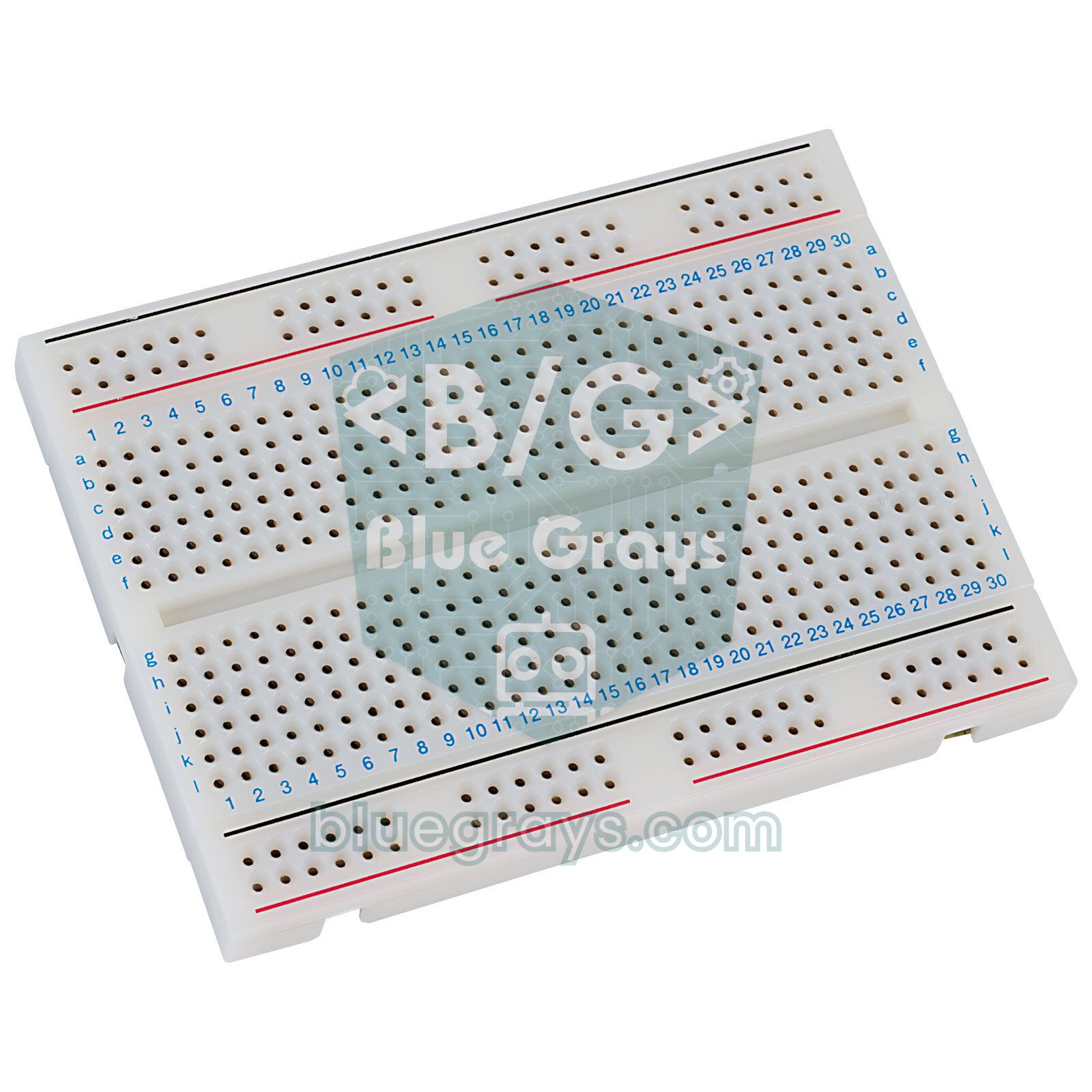
When you plug the Nano into a breadboard, place it so the two rows of pins sit on either side of the centre channel. That way each pin lands in its own strip, and you can connect wires to that pin through the strip's free holes. Because the board covers the channel and the holes between the pins, only a few holes remain next to each pin; on common 830-point breadboards, if you centre the board over the channel you get 2 free holes on one side and 3 on the other. Facing the USB socket towards the short edge of the breadboard makes the cable easy to plug in. Then connect the Nano's 5V and GND pins to the breadboard's red and blue power rails so you can power sensors from there. To refresh your memory on how a breadboard is wired inside, see What is a breadboard?.
- Soldering the headers: On clones that come with loose pins, first push the male headers into the breadboard, rest the Nano on top and solder it like that; the breadboard holds the headers straight and exactly 0.6 in apart. You'll find the technique in How to solder.
- Removing it: Lifting the board from one end bends the pins; lift both ends a little at a time, or slide a flat screwdriver underneath and pull it out evenly.
- Loose contacts: On old or cheap breadboards the springs wear out; the Nano resets now and then or a sensor drops out occasionally. Try moving the board to another area of the breadboard.
- Nano expansion board: In a permanent project, a Nano I/O shield with screw terminals or 3-pin headers that give signal, 5V and GND for every pin greatly reduces the wiring mess.
- Mini breadboard: Small 170-point breadboards have no power rails; route 5V and GND to separate strips and mark them with wire colours.
Arduino Uno to Nano pin mapping table
| Function | Arduino Uno R3 | Arduino Nano | Note |
|---|---|---|---|
| Digital I/O | D0–D13 | D0–D13 | Same numbers and functions |
| PWM | ~3, 5, 6, 9, 10, 11 | ~3, 5, 6, 9, 10, 11 | Same frequencies and timers |
| Analog input | A0–A5 | A0–A7 | A6 and A7 exist only on the Nano and are analog-only |
| I2C SDA / SCL | A4 / A5 (copy next to AREF) | A4 / A5 | No separate SDA/SCL pins on the Nano |
| SPI SS / MOSI / MISO / SCK | 10 / 11 / 12 / 13 | 10 / 11 / 12 / 13 | Both also have them on the ICSP header |
| External interrupts | D2, D3 | D2, D3 | Same |
| Built-in LED | D13 (op-amp buffered) | D13 (connected directly to the pin) | Take care using D13 as an input on the Nano |
| Power input | DC jack and Vin, 7–12 V | VIN pin only, 7–12 V | No jack on the Nano |
| USB | USB-B; ATmega16U2 or CH340 | Mini-B; FT232RL or CH340 | Different cables |
| 3.3V output | Separate regulator, 50 mA | From the USB chip, very limited | Don't power modules from it on the Nano |
| IOREF | Yes | No | For shield compatibility |
| Space for code | 32,256 bytes | 30,720 bytes | The IDE reserves 2 KB on the Nano |
| Fitting shields | Directly | With an adapter or expansion board | - |
As the table shows, moving a circuit built for the Uno over to the Nano only means connecting the wires to the pins with the same numbers: a servo on D9 of the Uno goes to D9 on the Nano, and an I2C display on A4/A5 still goes to A4/A5. The only change in the code is selecting Arduino Nano under Tools > Board. Shields that plug straight into the Uno won't fit the Nano, though; for that there are adapter boards that convert the Nano to the Uno pin layout. You'll find the detailed role of every pin on the Uno in Arduino Uno pinout, and help choosing a board in Which Arduino should I buy?.
Nano Every and Nano ESP32: how they differ from the classic Nano
| Feature | Classic Nano (V3) | Nano Every | Nano ESP32 |
|---|---|---|---|
| Processor | ATmega328P, 8-bit, 16 MHz | ATmega4809, 8-bit, 16 MHz in the IDE (up to 20 MHz) | ESP32-S3, dual-core, 32-bit, 240 MHz |
| Flash / SRAM | 32 KB / 2 KB | 48 KB / 6 KB | 16 MB / 512 KB (+8 MB PSRAM) |
| Logic voltage | 5 V | 5 V | 3.3 V (not 5 V tolerant) |
| USB | Mini-B | Micro-B | USB-C |
| VIN range | 7–12 V recommended | 7–21 V | 6–21 V |
| PWM pins | D3, D5, D6, D9, D10, D11 | D3, D5, D6, D9, D10 (not on D11) | Nearly all digital pins |
| A6 / A7 | Analog only | Analog and digital | Analog and digital |
| External interrupts | D2, D3 only | All digital pins | All pins |
| D0 / D1 serial line | Shared with USB (Serial) | Separate from USB (Serial1) | Separate from USB (Serial0) |
| Wireless | None | None | Wi-Fi and Bluetooth LE |
| IDE board package | Arduino AVR Boards | Arduino megaAVR Boards | Arduino ESP32 Boards |
The Nano Every is a more powerful version of the classic Nano with the same size and the same pin layout. It has an ATmega4809 inside, runs at 5 V and offers 48 KB of flash and 6 KB of SRAM, so OLED and LED strip projects that struggle with the classic Nano's RAM get some breathing room. On the USB side a SAMD11 chip acts as a bridge and code is uploaded through the UPDI interface, so there's no Old Bootloader hassle. To use the board, install the Arduino megaAVR Boards package from the Boards Manager. The differences to watch out for: PWM is only on D3, D5, D6, D9 and D10 (D11 has no PWM), A6 and A7 also work as digital pins, every digital pin can be used as an external interrupt, and D0 and D1 are a Serial1 port independent of USB. The Tools > Registers emulation > ATMEGA328 setting emulates port registers such as PORTB, but old code that writes directly to timer or ADC registers still won't work. The sketch below shows two of the Every's differences together: it talks to a module on D0/D1 while the Serial Monitor is open, and it uses A7 as a button input with the internal pull-up.
1// Nano Every: Serial = USB, Serial1 = D0 (RX) ve D1 (TX) / Serial = USB, Serial1 = D0 (RX) and D1 (TX)
2const byte BUTTON_PIN = A7;            // Every'de A7 dijital de çalışır / A7 also works as digital on the Every
3
4bool lastState = HIGH;
5
6void setup() {
7  Serial.begin(9600);                  // Seri Monitör / Serial Monitor
8  Serial1.begin(9600);                 // D0/D1'deki modül, ör. HC-05 / module on D0/D1, e.g. HC-05
9  pinMode(BUTTON_PIN, INPUT_PULLUP);   // klasik Nano'nun A7'sinde çalışmaz / does not work on the classic Nano's A7
10}
11
12void loop() {
13  if (Serial1.available()) {
14    Serial.write(Serial1.read());      // modülden bilgisayara / module to computer
15  }
16  if (Serial.available()) {
17    Serial1.write(Serial.read());      // bilgisayardan modüle / computer to module
18  }
19  bool state = digitalRead(BUTTON_PIN);
20  if (state != lastState) {            // durum değişince bildir / report when the state changes
21    lastState = state;
22    Serial1.println(state == LOW ? "Buton basildi / Button pressed" : "Buton birakildi / Button released");
23    delay(20);                         // kontak sıçraması / contact bounce
24  }
25}
The Nano ESP32, on the other hand, is a whole different world in the same board size: the ESP32-S3 processor in the u-blox NORA-W106 module runs at 240 MHz and offers Wi-Fi and Bluetooth LE. The most important difference is voltage: all pins run at 3.3 V and are not 5 V tolerant, so a sensor with a 5 V output that you'd connect straight to a classic Nano can damage the Nano ESP32. Where the classic Nano has its 5V pin, there's a VBUS pin, which provides 5 V only while the board is powered over USB; when powered through VIN, this pin is dead. In place of AREF and the RST pin on the analog side you'll find BOOT0 and BOOT1. The board is programmed with the Arduino ESP32 Boards package, and the Tools > Pin Numbering menu has two options: in the default By Arduino pin setting the D and A names printed on the board apply, while in By GPIO number the numbers are the ESP32's GPIO numbers. For example, D2 is actually GPIO5; in GPIO mode, writing pinMode(2, OUTPUT) configures pin A1 instead. If you always write pins by name, like D2 and A0, your code works correctly in both modes.
1// Nano ESP32: Araçlar > Pin Numbering > By Arduino pin (default)
2// Nano ESP32: Tools > Pin Numbering > By Arduino pin (default)
3bool ledOn = false;
4
5void setup() {
6  Serial.begin(115200);                // USB-C üzerinden / over USB-C
7  pinMode(LED_BUILTIN, OUTPUT);        // D13 = GPIO48
8  pinMode(LED_RED, OUTPUT);
9  pinMode(LED_GREEN, OUTPUT);
10  pinMode(LED_BLUE, OUTPUT);
11  digitalWrite(LED_RED, HIGH);         // RGB LED ters mantık: HIGH = sönük / active low: HIGH = off
12  digitalWrite(LED_GREEN, HIGH);
13  digitalWrite(LED_BLUE, HIGH);
14  analogReadResolution(12);            // 0-4095 arası / range 0-4095
15}
16
17void loop() {
18  int raw = analogRead(A0);            // 12 bit ham değer / 12-bit raw value
19  int mv = analogReadMilliVolts(A0);   // kalibre edilmiş milivolt / calibrated millivolts
20  Serial.printf("A0: %d  (%d mV)\n", raw, mv);
21  digitalWrite(LED_GREEN, mv > 1650 ? LOW : HIGH);   // 1,65 V üstünde yeşil / green above 1.65 V
22  digitalWrite(LED_RED, mv > 1650 ? HIGH : LOW);     // altında kırmızı / red below
23  ledOn = !ledOn;
24  digitalWrite(LED_BUILTIN, ledOn ? HIGH : LOW);     // D13 LED'ini yakıp söndür / blink the D13 LED
25  delay(500);
26}
The Nano ESP32's analog inputs take 12-bit readings and return values from 0 to 4095, while analogReadMilliVolts() uses the chip's calibration data to give the result directly in millivolts. The on-board RGB LED works with inverted logic, so it lights up when you write LOW. If code won't upload and the board disappears from the port list, you can put it into bootloader mode by pressing the reset button twice in quick succession. To learn about the Wi-Fi side of the ESP32, see What is the ESP32?, and to settle on a board, read Arduino or ESP32?. Among the other members of the family, the Nano R4 brings the same 48 MHz Renesas RA4M1 processor as the Uno R4 to the 5 V Nano format but supplies only 8 mA per pin, while the Nano 33 IoT and Nano 33 BLE are 3.3 V boards like the Nano ESP32.
Arduino Nano project ideas
- Pocket thermometer: Show the temperature measured with a DHT11 on a small OLED display; the Nano and the display fit in a matchbox.
- Mini robot car: The Nano's small size saves space on the chassis; drive the motors with an L298N and follow the steps in Building a robot car.
- Line-following robot: Eight analog inputs are more than enough to read a five-sensor array; the details are in Line-following robot.
- Bluetooth remote: Connect an HC-05 module to D8 and D7 with SoftwareSerial and control an LED or relay from your phone; D0 and D1 stay free for uploading.
- Wearable light: Make a badge or bag light with a battery-powered Nano and a few WS2812B LEDs.
- A keypad on one pin: Build the resistor ladder above on both A6 and A7 for an eight-button menu, and keep the digital pins for the display and motors.
- Want a USB keyboard? The classic Nano's ATmega328P has no built-in USB, so it can't appear to a computer as a keyboard or mouse; for that you need ATmega32U4 boards such as the Leonardo and Pro Micro.
Common mistakes and how to fix them
| Symptom | Cause | Fix |
|---|---|---|
| The Nano doesn't appear in the port list | Charge-only cable or missing CH340 driver | Use a data cable, install the CH341SER driver; remove brltty on Linux |
| Upload stops with a "not in sync" error | The board has the old bootloader | Tools > Processor > ATmega328P (Old Bootloader) |
| A button on A6 or A7 doesn't respond at all | These pins have no digitalRead or internal pull-up | Add an external 10 kΩ pull-up and use a threshold with analogRead |
| A button on D13 always reads as pressed | The L LED and its resistor pull the pin down | Move the button to another pin |
| A module powered from 3V3 is unstable or dead | The 3V3 pin supplies very little current | Use a separate 3.3 V regulator fed from 5V |
| Analog readings are a few percent too high | On USB the 5V pin is about 4.7 V | Measure the real Vcc or power the board through VIN |
| The board gets very hot with 12 V on VIN | The regulator dissipates (12 − 5) × current as heat | Feed 7–9 V into VIN or power the 5V pin from a buck module |
| With a servo attached, the LED on D9/D10 won't dim | The Servo library uses Timer1 | Move the LED to D3, D5, D6 or D11 |
The Arduino Nano is the easiest way to take everything you've learned on the Uno into small, permanent projects; as long as you know the differences around A6/A7, 3V3 and the bootloader, there won't be any surprises. If you want to go back to basics, start with What is Arduino?. In the BlueGrays app you'll find step-by-step projects with circuit diagrams and ready-made code for blinking an LED, an LED with a button, measuring light with an LDR, distance with the HC-SR04, temperature and humidity with the DHT11, an RGB LED, a servo with a potentiometer and serial communication between two Arduinos; they all work on the Nano with the same pin numbers.
Frequently asked questions
How many pins does an Arduino Nano have?
The classic Arduino Nano has 30 pins in two rows. 14 of them are digital inputs/outputs (D0–D13), 8 are analog inputs (A0–A7), and the rest are VIN, 5V, 3V3, AREF, two GND and two RST pins. Since A0–A5 can also be used as digital pins, you get 20 digital pins; A6 and A7 can only read analog values.
Which pins are PWM on the Arduino Nano?
The PWM pins are D3, D5, D6, D9, D10 and D11; on the board or in pinout diagrams they're marked with a ~ next to the number. D5 and D6 run at about 980 Hz, the others at about 490 Hz. The Servo library affects PWM on D9 and D10, and the tone() function affects D3 and D11.
Can A6 and A7 on the Arduino Nano be used as digital pins?
No. A6 and A7 are two ATmega328P channels connected only to the analog-to-digital converter; pinMode, digitalRead, digitalWrite and the internal pull-up don't work on these pins. To read a button, add an external 10 kΩ pull-up resistor and compare the analogRead() value against a threshold. On the Nano Every and Nano ESP32, however, A6 and A7 can also be used as digital pins.
What voltage can I supply to an Arduino Nano?
You can power the Nano over USB, with 7–12 V on the VIN pin, or with regulated 5 V on the 5V pin. The AMS1117 regulator on clone boards can fail above 15 V and heats up quickly even at 12 V, so 7–9 V is ideal for VIN. Never put more than 5 V on the 5V pin.
What does Old Bootloader mean on the Arduino Nano?
In 2018 Arduino replaced the Nano's bootloader with the smaller, faster Optiboot; the new bootloader communicates at 115200 baud and the old one at 57600 baud. Most clone Nanos on the market still have the old bootloader, so unless you select ATmega328P (Old Bootloader) under Tools > Processor, the upload stops with a not in sync error. Choosing the wrong option doesn't harm the board, so you can simply try both.
What is the difference between the Arduino Nano and Uno?
Both use a 16 MHz ATmega328P, so the pin numbers, PWM pins, I2C (A4/A5) and SPI (D10–D13) lines and the code are the same. The Nano is smaller, plugs into a breadboard and has two extra analog inputs (A6, A7), but it has no DC jack and no shield headers. The Nano also uses mini USB and the IDE gives it 30,720 bytes for code, while the Uno's limit is 32,256 bytes.
Projects to build after reading this
See all projects
LED Blink
The very first hello of electronics: switching a single LED on and off. The Arduino turns the LED on and off at short intervals, so the light blinks quickly. You see in the simplest way how the board

LED Control with a Push Button (Push)
Just like a doorbell: the light stays on as long as you press, and goes off when you let go. The Arduino keeps listening to the button; while it's pressed the LED is on, and the moment you lift your f

Measuring Light Intensity with an LDR
Want to see how bright your room is as a number? The LDR, a small part that reacts to light, measures the light around it, and the Arduino writes the value to your computer screen every half second. C
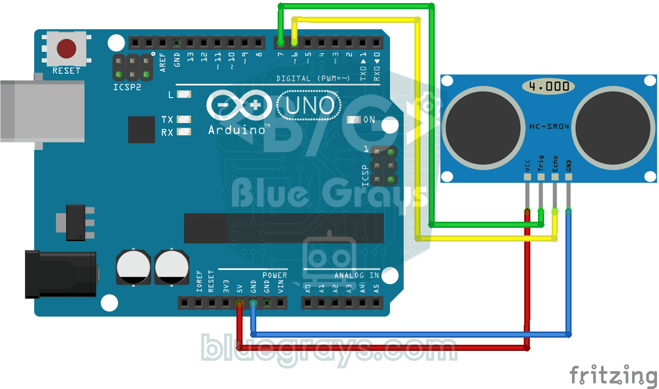
HC-SR04 Distance Measurement (Serial Display)
The HC-SR04 sensor works just like a bat finding its way in the dark: it sends out a sound you cannot hear, listens for the echo and measures how far away the object in front of it is. The Arduino wri
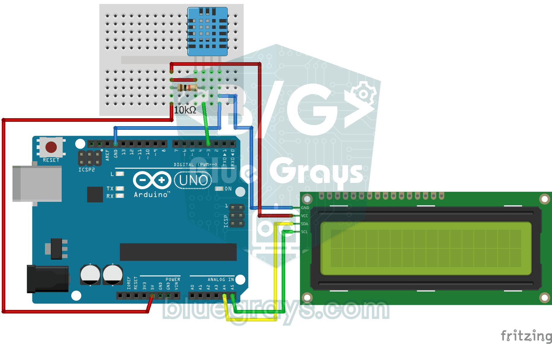
Temperature and Humidity with DHT11
How warm is your room, and is the air humid or dry? The DHT11 sensor measures temperature and humidity, and the Arduino writes the values on a two-line LCD screen, refreshing every couple of seconds.
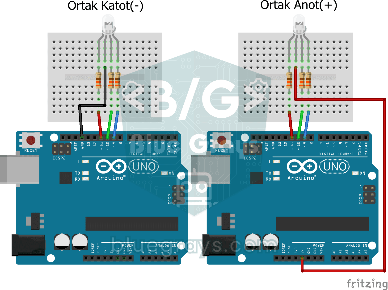
Using an RGB LED
Three colours hide inside a single LED: the RGB LED lights up red, then green, then blue, each colour on for half a second and off for half a second, before the cycle starts again. All you need is one
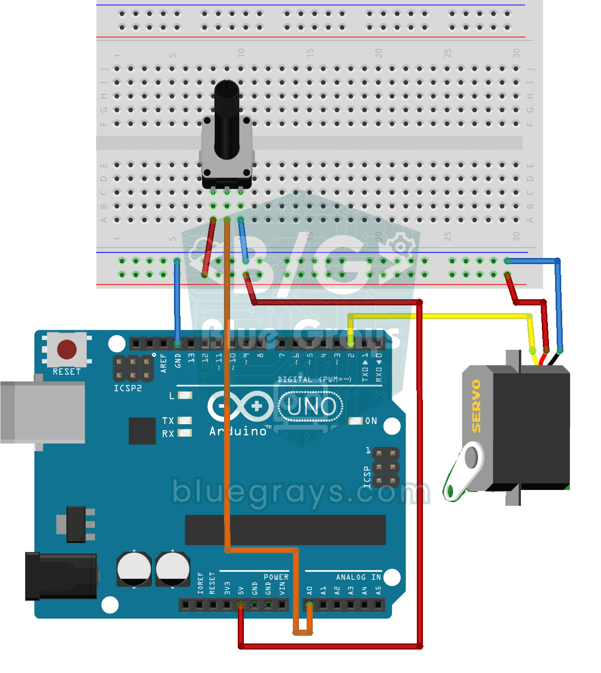
Servo Motor Operation with Potentiometer
As you turn the potentiometer knob, the servo motor's arm turns right along with it: one end of the knob means zero degrees, the other end means half a turn. The Arduino keeps reading the knob's posit
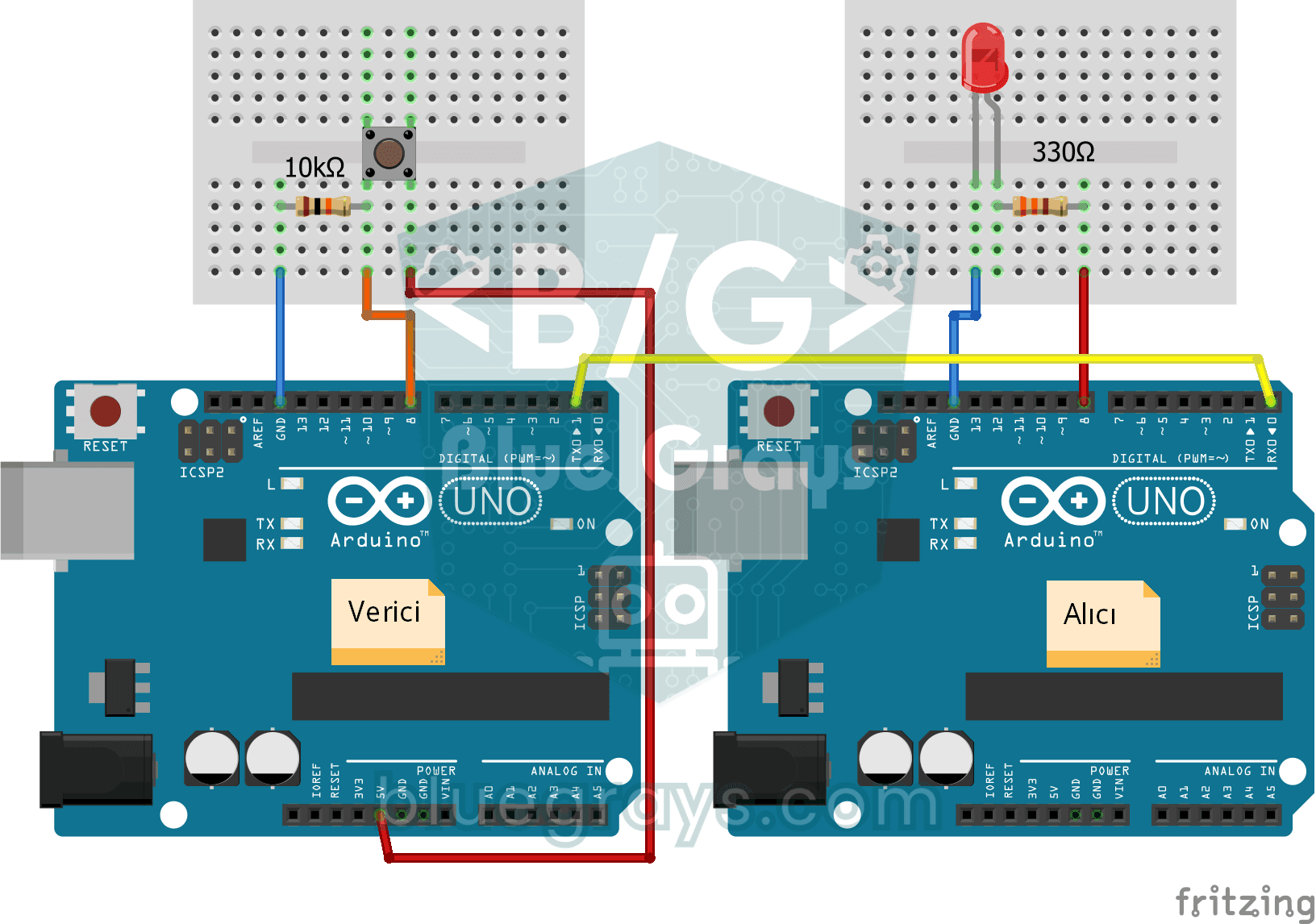
One-Way Communication Between 2 Arduinos
You get two Arduinos talking over a single wire: press the button on one and the LED on the other lights up, press it again and it goes off. The sending board reports the button press with a short mes