
First Arduino Project Step by Step: A 4-Step Guide on Your Phone
Your first Arduino project step by step: the app's guided mode walks you through a free Traffic Light build with a parts list, wiring, upload and a time plan.
If you want to build your first Arduino project step by step without knowing anything yet, there is a way to be guided on your phone: open a project page in BlueGrays and tap Build it step by step. The guided mode, called Let's build it together, splits the project into four steps: Get the parts ready, Build the circuit, Upload the code and Run and test. Each step shows only what you need right then, your phone screen stays on while you plug in wires, and if you stop halfway the button on the project page shows the step where you left off. All you need is an Arduino Uno, a few cheap parts and a computer to upload the code to the board.
In this post we don't just describe the mode, we use it on a real project from start to finish: we build the free Traffic Light project from the app in four steps. You will find the parts table, which wire goes to which pin, choosing the board and port in the Arduino IDE, the expected result, where to look when you get stuck, a 45–60 minute time plan and three small experiments for after your first project. If you want to know what each section of a project page does, we covered that in the project page guide; here we focus only on the flow of the guided mode.
What is the guided mode and where do you find it?
When you open a project, the main button of the page, Build it step by step, sits below the title, the rating and the short description; the small line under it sums up the four stops: Parts · Circuit · Code · Test. Tap it and, instead of the project page, a clean screen opens that shows one step at a time. At the top you see Screen stays on and a Step 1 / 4 counter, at the bottom the Back and Next step buttons. Your current step and the parts you ticked are saved; if you close the app and come back the next day, the button reads something like Continue · Step 2 / 4 and you pick up where you stopped. On free projects every step of the guide is open; on Premium projects the guide, like the project itself, opens with Premium.
| Step | What you see | What you do | When you move on |
|---|---|---|---|
| 1. Get the parts ready | The parts list with quantities and a progress bar such as "5 / 5 parts ready" | Find the parts on your desk and tick them one by one | When every part is ticked |
| 2. Build the circuit | The circuit diagram (tap to zoom) and the USB tip | Plug in the wires in the order of the diagram | When you have checked every connection against the diagram |
| 3. Upload the code | Source code, Show as blocks, Understand the code and an Arduino IDE tip | Move the code to your computer and upload it to the board | When the Arduino IDE says the upload is done |
| 4. Run and test | The project video ("It should work like this:"), I'm stuck and It works! buttons | Compare how your circuit behaves with the video | When it behaves like the video |
Example project: why the Traffic Light?
Traffic Light is one of the free, Beginner-level projects in BlueGrays: the red LED stays on for two seconds, yellow flashes briefly, green stays on for two seconds, then it goes back to red via yellow and the loop never stops. It is a good first project because it is one step beyond blinking a single LED but needs no new concept: you repeat the same three commands (pinMode, digitalWrite, delay) for three pins. Everyone knows what a traffic light looks like, so you can tell right away whether it works, and the parts come in every starter kit. If you want an even simpler start, the LED Blink project goes through the same four steps with one LED and two wires. Versions with a pedestrian button, an intersection and millis() are in the Arduino traffic light post; that post uses different pins, so follow the connections here as they appear in the app's project.
Step 1: Get the parts ready
The first screen shows 1. Get the parts ready and the note "Tick what you have. Spot anything missing now." Below it the project's parts are listed with quantities; find each part on your desk, tap it in the list to tick it, and the bar at the top fills up, for example "3 / 5 parts ready". If you use Premium and have saved your parts in your Workshop, the parts you have in sufficient quantity come pre-ticked with an In your workshop label. Don't rush this step: finding out halfway through the build that the third resistor is missing is far more annoying than noticing it before you start.
| Part | Qty | Specification | Note |
|---|---|---|---|
| Arduino Uno | 1 | Uno R3 or a compatible clone | Clone boards may need a driver for uploading |
| Breadboard | 1 | Half size, 400 holes | A full-size one works too |
| LED | 3 | 5 mm; red, yellow, green | Different colors still work |
| Resistor | 3 | 330 Ω (330R in the list) | One per LED; 220 Ω also works |
| Jumper wire | 7 | Male to male | 3 pin wires, 3 LED returns, 1 GND |
| USB cable | 1 | Type A-B (not in the list) | Uploads the code and powers the board |
| Computer | 1 | Arduino IDE installed (not in the list) | Windows, macOS or Linux |
If a part is missing you usually don't have to give up. You can use 220 Ω instead of 330 Ω resistors; the LED gets a bit brighter and both values are safe. If you don't know the value of a resistor, enter its color bands in the resistor color code tool: 330 Ω reads orange-orange-brown, 220 Ω reads red-red-brown, and a fourth gold band is the tolerance. For another LED you can find the right resistor with the LED resistor calculator. If your LED colors are different (three red ones, say) the project still works, you just lose the traffic light look. If you don't have a board yet, try the circuit first in a Tinkercad simulation, and check the Arduino starter kit guide before you go shopping.
Step 2: Build the circuit
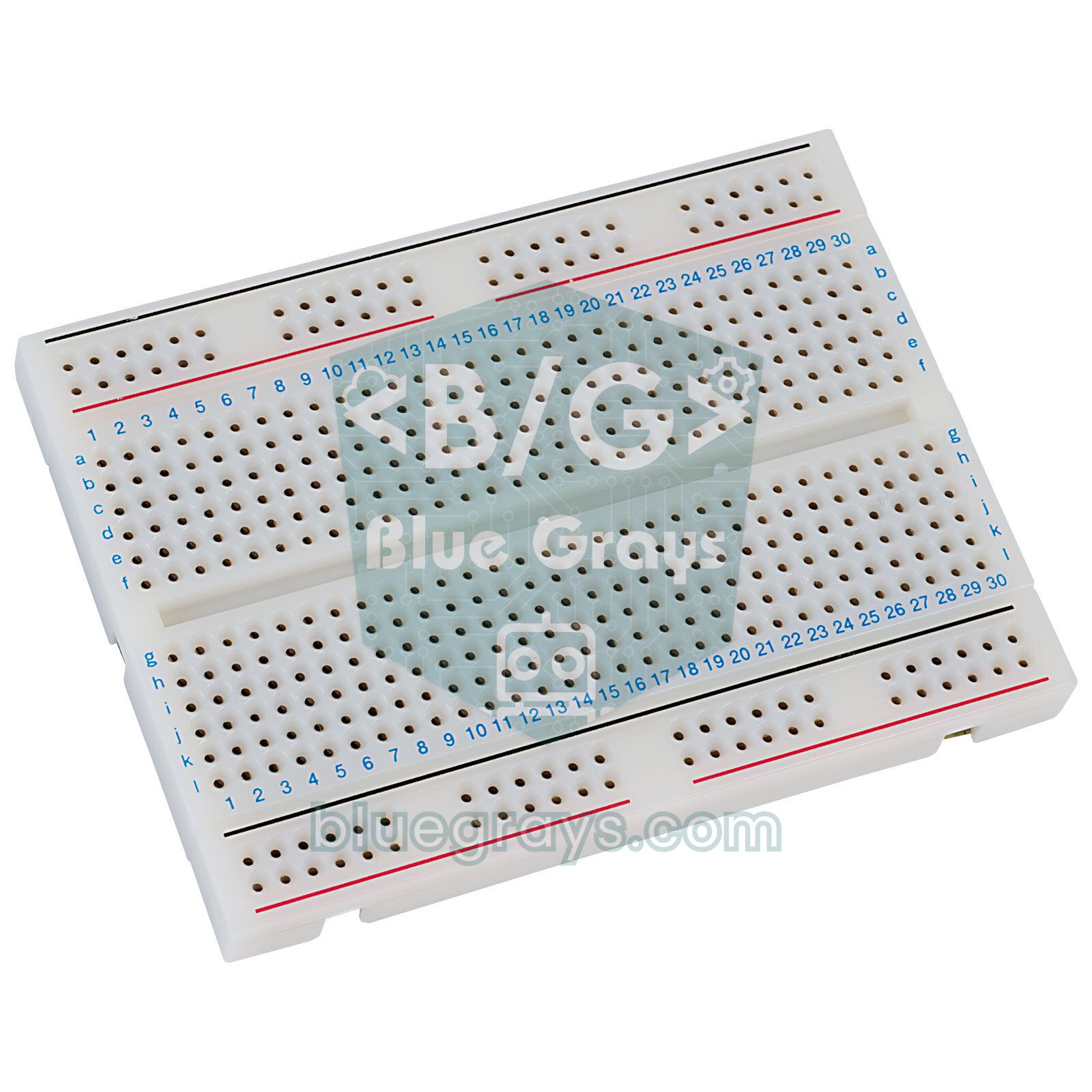
If you have never used a breadboard, one rule is enough: the five holes in a numbered column (A–E or F–J) are connected inside, and the groove in the middle separates the two halves. The long rows along the edges are the power rails; the one with the red line is for plus, the one with the blue line is for minus (GND), and they run the full length, although on some long breadboards they are split in the middle. In the Traffic Light diagram both legs of each LED go into two neighboring columns, a resistor jumps across the groove and carries one LED leg to the lower half, and the wire to the Arduino pin goes into the column where the lower end of the resistor sits. The other LED legs each go to the blue rail with a wire, and the blue rail goes to the Arduino's GND pin with a single wire. More detail in the what is a breadboard post.
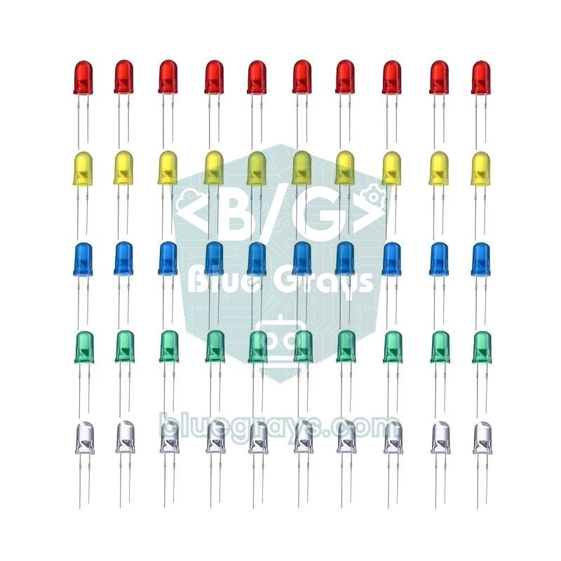
An LED only works one way round and stays dark when it is reversed. The long leg is the anode (+), the short leg is the cathode (-), and the body has a slightly flat edge on the short-leg side. In this project the long leg goes to the Arduino pin through the resistor and the short leg goes to GND. The resistor limits the current: the pin supplies 5 V, a red LED drops about 2 V, and the remaining 3 V across 330 Ω gives about 9 mA (3 / 330). With 220 Ω this rises to about 14 mA; both values are comfortable for the LED and the Arduino pin. An LED without a resistor can fail quickly and strains the pin. If you want to go deeper, the what is an LED and what is a resistor posts cover it.
| LED | Arduino pin | Long leg (+) | Short leg (-) |
|---|---|---|---|
| Red | 2 | To pin 2 through a 330 Ω resistor | To the GND rail with a wire |
| Yellow | 3 | To pin 3 through a 330 Ω resistor | To the GND rail with a wire |
| Green | 4 | To pin 4 through a 330 Ω resistor | To the GND rail with a wire |
| GND rail | GND | – | To the Arduino's GND pin with one wire |
- With the USB cable unplugged, start with GND: run a wire from the Arduino's GND pin to the breadboard rail with the blue line.
- Place the three LEDs on the upper half of the breadboard, from left to right green, yellow, red; each LED's two legs in separate columns, with all the long legs on the same side.
- From the column of each LED's long leg, add a 330 Ω resistor that crosses the groove to the lower half.
- Run a wire from the column of each LED's short leg to the blue GND rail.
- Run wires from the columns with the lower resistor ends to the Arduino: the red LED's resistor to pin 2, yellow's to pin 3, green's to pin 4.
- When you are done, trace every path with your finger: pin, wire, resistor, long leg, LED, short leg, GND. There should be no gap and no two ends in the same column.
- Tap the diagram in the guide to zoom in and compare it with your circuit; if everything matches, plug in the USB cable and go to Next step.
| Symptom | Likely cause | Fix |
|---|---|---|
| No LED lights up | The GND wire is missing or on the red rail instead of the blue one | Check the wire from the Arduino's GND to the blue rail |
| One LED stays dark | The LED is in backwards | Pull it out and plug it back in with the legs swapped |
| One LED stays dark although it faces the right way | Both LED legs are in the same column | Put the legs into two different neighboring columns |
| LED is very bright or doesn't light at all | Both resistor ends are in the same column | The resistor must join two separate columns; bridge it across the groove |
| Colors light up in the wrong order | Pin wires are swapped | Fix them so red is pin 2, yellow pin 3, green pin 4 |
| LEDs flicker now and then | A loose jumper wire | Push the wires all the way in and replace any suspicious one |
Step 3: Upload the code
This step shows the project's source code, the Show as blocks switch on projects that have blocks, and the Understand the code section that explains the code step by step. The computer, not the phone, uploads the code to the board, so first you need to install the Arduino IDE. In short: download the Arduino IDE 2 version for your operating system from the official Arduino website, install it and accept the driver prompts during installation; this usually takes about 10 minutes. The full walkthrough is in the Arduino IDE installation post. There are two ways to get the code onto your computer: use Copy and send it to yourself as a message, or use Copy Link to get a link that opens the code on your computer.
- Open the Arduino IDE, start a new sketch from the File menu, delete everything in it and paste the project's code.
- Connect the Arduino Uno to the computer with the USB cable; the board's ON light should be lit.
- In Tools > Board, choose Arduino Uno under Arduino AVR Boards.
- In Tools > Port, choose the port the board is connected to: on Windows something like COM3, on macOS a name starting with /dev/cu.usbmodem or /dev/cu.usbserial, on Linux something like /dev/ttyACM0.
- First compile with the check mark icon on the left (Verify); if there are no errors, press the arrow icon next to it (Upload).
- During the upload the small TX and RX lights on the board flicker; when the output panel at the bottom says the upload is done, go to Next step in the guide.
1// Trafik Lambası / Traffic Light
2void setup() {
3  pinMode(2, OUTPUT);   // Kırmızı LED / Red LED
4  pinMode(3, OUTPUT);   // Sarı LED / Yellow LED
5  pinMode(4, OUTPUT);   // Yeşil LED / Green LED
6}
7
8void loop() {
9  // Kırmızı yanar, 2 sn / Red on, 2 s
10  digitalWrite(2, HIGH);
11  digitalWrite(3, LOW);
12  digitalWrite(4, LOW);
13  delay(2000);
14  // Sarı yanar, 0,3 sn / Yellow on, 0.3 s
15  digitalWrite(2, LOW);
16  digitalWrite(3, HIGH);
17  digitalWrite(4, LOW);
18  delay(300);
19  // Yeşil yanar, 2 sn / Green on, 2 s
20  digitalWrite(2, LOW);
21  digitalWrite(3, LOW);
22  digitalWrite(4, HIGH);
23  delay(2000);
24  // Sarı yanar, sonra başa döner / Yellow on, then back to red
25  digitalWrite(2, LOW);
26  digitalWrite(3, HIGH);
27  digitalWrite(4, LOW);
28  delay(300);
29}
30| Line | What it does |
|---|---|
| pinMode(2, OUTPUT) | Makes pin 2 an output; the lines inside setup() run once when the board starts |
| digitalWrite(2, HIGH) | Puts 5 V on pin 2 and the red LED lights up; LOW turns it off |
| delay(2000) | Waits 2000 milliseconds (2 seconds); the LEDs keep their state meanwhile |
| loop() | Repeats its four sections in order forever; one cycle takes about 4.6 seconds |
Step 4: Run and test
In the last step the guide says "It should work like this:" and shows the project video. Your circuit starts as soon as the code is uploaded: red stays on for 2 seconds, yellow gives a short 0.3-second flash, green stays on for 2 seconds, then another short yellow and back to red. One full cycle takes about 4.6 seconds and two LEDs are never on at the same time. The very short yellow is not a bug, it comes from the delay(300) line in the code; if you keep missing it, watch the yellow LED for a few cycles. Compare your circuit with the video using three questions: are the colors in the right order, are the timings close to the video, is each LED bright enough? If the answer to all three is yes, the project works.
Then tap It works!. The project is marked as completed and after a short celebration the It works, congratulations! screen opens. There you can give the project 1 to 5 stars (Rate the project), move on through the WHAT TO BUILD NEXT card or go back with Back to project. If you use Premium and the project's parts are not saved in your Workshop, the app first asks Add the parts to your workshop?; choose Add and complete and the missing parts are added and the project is completed, so your Workshop shows correctly which projects you can build next time.
If you get stuck: I'm stuck, Understand the code and the forum
- I'm stuck: next to the It works! button in step 4, it opens the project's ready-made checks on the same screen. The Traffic Light has 10 checks covering power, port, pin numbers, breadboard, GND, LED direction and resistor value. On projects without ready tips it tells you that you can write to us from Profile › Support.
- Understand the code: below the code in step 3. It starts with a "What does this code do?" summary, explains the code step by step and ends with a small Try it yourself task. If the code works but you don't know why, continue here; how to use it is in the Understand the code guide.
- Forum: in Learn › Forum, start a new topic in the Question category, share a clear photo of your circuit (up to 5 images) and the code you uploaded with Add code. If you write in three sentences which project you built, what you expected and what happened, answers come more easily. Ohmi, the BlueGrays mascot, also answers questions in the forum.
- Before asking for help: unplug the USB cable, compare the circuit with the diagram one last time and upload the code again. Most problems in first projects come from one reversed LED or a single wire in the wrong column.
Time plan for your first Arduino project
For a complete beginner, the Traffic Light takes 45–60 minutes including the computer setup. There is no need to hurry; the longest part is building and checking the circuit. On your second project the Arduino IDE and the board and port settings are already done, so the same flow drops to 25–30 minutes.
| Part | Time | What you do |
|---|---|---|
| Preparation | 10–15 min | Download and install the Arduino IDE, test the USB cable |
| Step 1: Get the parts ready | 5 min | Lay the parts out, tick them in the guide, check the resistors by color code |
| Step 2: Build the circuit | 15–20 min | Place 7 wires, 3 LEDs and 3 resistors following the diagram, trace every path |
| Step 3: Upload the code | 5–10 min | Move the code to the computer, choose board and port, Verify and Upload |
| Step 4: Run and test | 5 min | Compare with the video, finish with It works!, rate it |
| First experiment | 5 min | Change one delay value and upload again |
| Total | 45–60 min | 25–30 min on the second project, with no setup |
A sequence for your first 5 projects
After the Traffic Light, adding one new concept per project is the calmest way to learn. All five projects below are free in BlueGrays, with the circuit diagram, parts list, code, blocks and Understand the code open. You build each one with the guided mode in the same four steps, and each adds at most one or two new parts to what you already have.
| Order | Project | New concept | New parts |
|---|---|---|---|
| 1 | Traffic Light | Digital output, order of commands, delay() | 3 LEDs, 3 resistors |
| 2 | LED Police Lights | A variable and a for loop for counted repeats | No new parts, 2 LEDs are enough |
| 3 | LED Control with a Push Button (Push) | Reading an input, deciding with if / else | Push button, 10k resistor |
| 4 | Night Light with Ldr | analogRead() values from 0 to 1023 and a threshold | LDR (light sensor) |
| 5 | Using a Buzzer | Sound frequency with tone() and noTone() | Buzzer |
If you want to leave this path, the app's Project Finder suggests projects that suit you, plus a free warm-up project with the same parts, when you pick This will be my first project for the question "How much experience do you have?". If you want to plan day by day what comes after these five, the 30-day Arduino roadmap takes you into weeks two and three.
After your first project: 3 small experiments
- Change the timings. Change red's delay(2000) to delay(5000), change both yellow delay(300) lines to delay(1000) and upload again. A cycle grows from 4.6 to 9 seconds and looks more like a real traffic light. This experiment shows that the number in the code is directly the behavior of the circuit.
- Add a second green LED for pedestrians. Take one more LED, a 330 Ω resistor and two wires, build the same connection on the free pin 5 and add pinMode(5, OUTPUT) to setup(). Write digitalWrite(5, HIGH) in the section where red is on and digitalWrite(5, LOW) in the other three. Pedestrians see green while cars wait at red; seeing which lines change to add one LED reinforces the idea of pins and outputs.
- Make yellow blink. Replace the yellow section after green with three repeats that turn yellow on for 300 ms and off for 300 ms. First copy the lines three times by hand, then do the same with a for (int i = 0; i < 3; i++) loop. This is a natural lead-in to the main idea of the next project, LED Police Lights.
The real gain of your first Arduino project is not three glowing LEDs but the four-step flow itself: knowing the parts, building the circuit from a diagram, uploading the code and comparing the result with the expected behavior. That flow is the same for the Traffic Light and for a sensor project you will build months from now. When you open BlueGrays on your phone and tap Build it step by step on the Traffic Light, every step in this post will be waiting for you on screen.
Frequently asked questions
What should my first Arduino project be?
A project that uses only LEDs, resistors and wires, such as blinking one LED or a traffic light, is the easiest start. These projects teach digital output, the delay() command and how a breadboard works all at once, and the parts come in every starter kit. The LED Blink and Traffic Light projects in BlueGrays are free.
Can I build an Arduino project with no experience?
Yes. In your first projects you don't need to write code from scratch; uploading the ready-made code and building the circuit from the diagram is enough. You learn what the code does later by reading it line by line. What matters is applying a few basic rules correctly: LED direction, the resistor and breadboard columns.
How long does a first Arduino project take?
45–60 minutes including the Arduino IDE setup is realistic. Setup takes about 10–15 minutes, building the circuit 15–20 minutes, and uploading and testing 10–15 minutes. From the second project on there is no setup, so it drops to 25–30 minutes.
Can I upload Arduino code from my phone?
Code is uploaded to boards like the Arduino Uno with the Arduino IDE on a computer over USB. In BlueGrays the phone acts as your guide: it shows the parts, the circuit diagram, the code and the test step by step, and you move the code to your computer with Copy or Copy Link. On a Raspberry Pi Pico you use Thonny for this.
Why won't my Arduino LED light up?
The most common reason is a reversed LED: the long leg (+) must go to the pin through the resistor and the short leg to GND. Then check the GND wire, whether the pin number in the code matches the circuit, and that both LED legs are not in the same breadboard column. If you suspect the LED is broken, try another one.
Is the guided mode free?
On free projects all four steps of the guided mode are open; the Traffic Light and LED Blink are two of them. 60 projects in BlueGrays, 20 per platform, are completely free. On Premium projects the guide, like the project itself, opens with Premium.
Projects to build after reading this
See all projects
Traffic Light
A tiny copy of the traffic light you see on the road every day. Red stays on for two seconds, yellow flashes for a moment, green stays on for two seconds, then it goes back to red through yellow again

LED Blink
The very first hello of electronics: switching a single LED on and off. The Arduino turns the LED on and off at short intervals, so the light blinks quickly. You see in the simplest way how the board

Two LEDs Blinking Alternately
Two LEDs blink quickly in turn: when one lights up the other goes off, as if they were tossing a ball back and forth. The Arduino keeps each light on for a fifth of a second and then hands over to the

LED Police Lights
Just like the lights on a police car: the red LED flashes three times in quick succession, then the blue LED flashes three times, and the pattern keeps repeating without a break. All you need is two L

LED Control with a Push Button (Push)
Just like a doorbell: the light stays on as long as you press, and goes off when you let go. The Arduino keeps listening to the button; while it's pressed the LED is on, and the moment you lift your f

Night Light with Ldr
A little night light that turns on by itself when it gets dark and goes off when morning comes. A light sensor measures how bright the room is, and the Arduino switches the LED on when it is dark enou
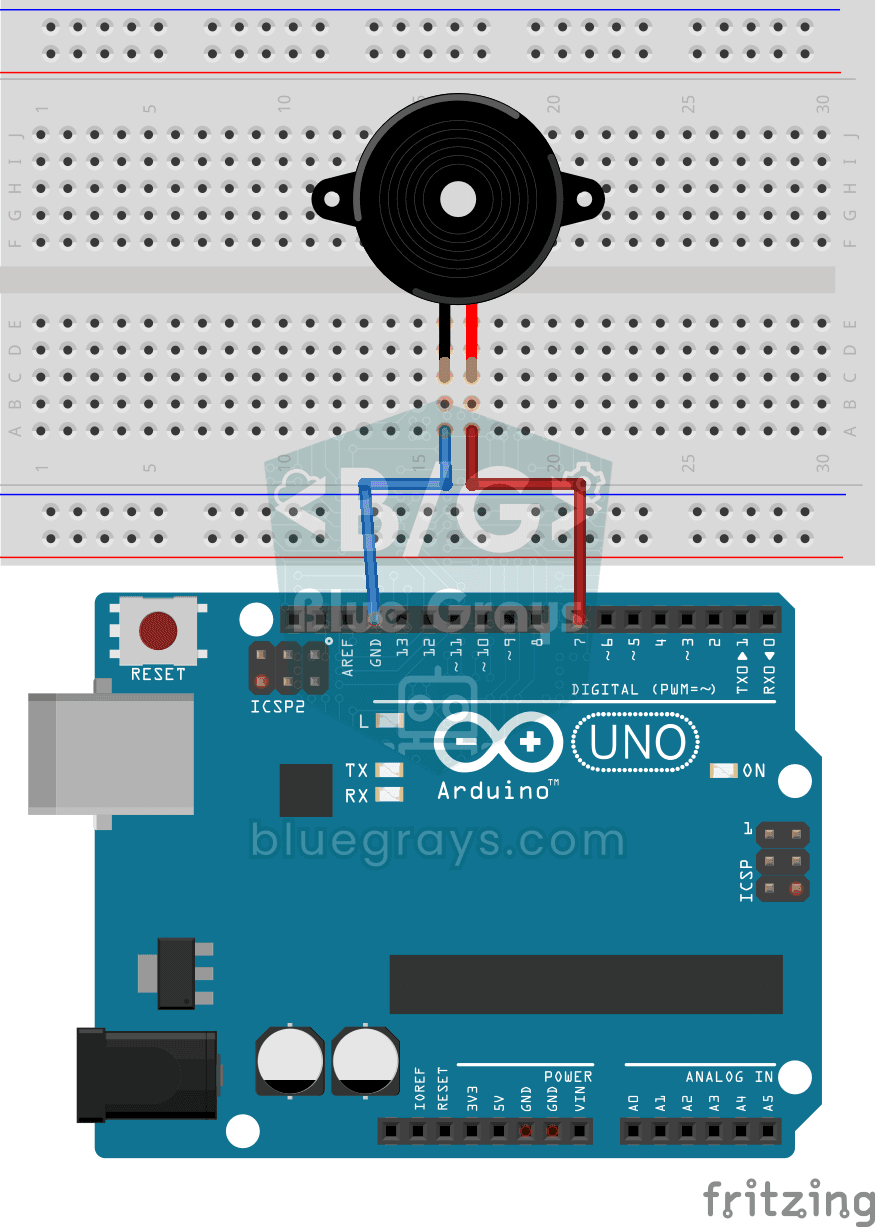
Using a Buzzer
Ever wondered how a doorbell or an alarm makes its sound? The Arduino makes a small buzzer beep at short intervals: beep, pause, beep, pause. You see how sound is made with electricity and take the fi

Measuring Light Intensity with an LDR
Want to see how bright your room is as a number? The LDR, a small part that reacts to light, measures the light around it, and the Arduino writes the value to your computer screen every half second. C