
Float Switch Arduino: Pump and Tank Level Control Guide
How do you wire a float switch to Arduino? Reed basics, NO/NC mounting, pull-up reading, and Uno, ESP32 and Pico code to stop the pump when the tank fills.
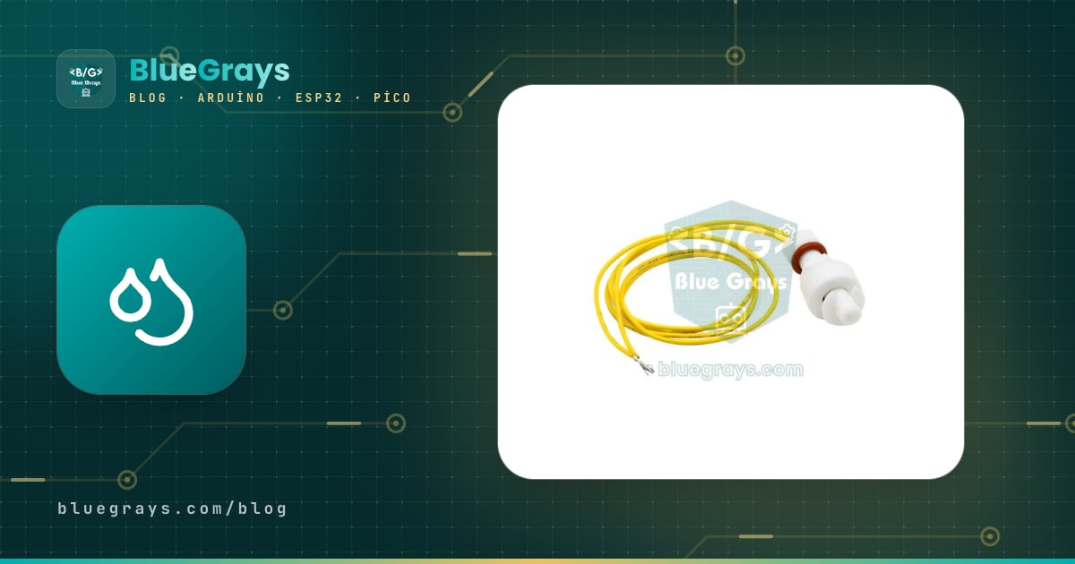
A float switch is the simplest and most reliable way to tell with an Arduino whether a water tank, aquarium or irrigation reservoir is full or empty. Inside is a float with a magnet and a reed switch in a glass tube; when the water level pushes the float up the contact closes, and when the water drops it opens. Electronically, the sensor is just a button pressed by water: you connect one of its two wires to GND and the other to a digital pin, and read the pin with INPUT_PULLUP.
In this guide you'll learn what's inside the float, the difference between NO and NC mounting, how to filter out the jitter caused by rippling water in software, and you'll build step by step a circuit with two floats that automatically stops the pump when the tank is full. Along with working code for Arduino Uno, ESP32 and Raspberry Pi Pico, you'll see when a float is better than conductive probe, contactless and ultrasonic level sensors.
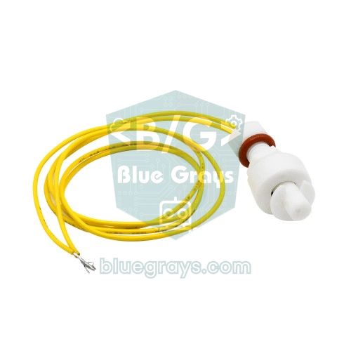
What is a float level sensor and how does it work?
Inside the hollow plastic body in the middle of the sensor there is a small glass tube filled with inert gas. Inside the tube are two ferromagnetic metal reeds sitting very close together; this is the reed switch. The float that slides freely along the body contains a ring-shaped magnet. As the water rises, the float lifts and slides along the body; when the magnet reaches the reed switch, its magnetic field magnetizes the two reeds, they attract each other and the circuit closes. When the magnet moves away, the springiness of the reeds separates them and the circuit opens again.
This design has two big advantages. First, the electrical contact is entirely inside a sealed glass tube; no metal touches the water, so you don't get the electrolytic corrosion or fouling that conductive probe sensors suffer from. Second, the output is purely digital: either open or closed. No analog reading, calibration or library is needed. On the other hand, a float knows only a single point; it can't tell you whether the water is 12 cm or 18 cm deep, it only answers "is the level above or below this line?". The same principle is used in door and window sensors; see the Reed Relay article for details.
| Feature | Typical value (small vertical model) |
|---|---|
| Sensing element | Reed switch + ring magnet inside the float |
| Output | Dry contact (open / closed), 2 wires, non-polarized |
| Contact type | NO or NC (changed by flipping the float) |
| Max. switching power | 10 W |
| Max. switching voltage | 100 V DC |
| Max. switching current | 0.5 A |
| Contact resistance | 100 mΩ or less |
| Body and float material | PP (polypropylene) |
| Operating temperature | −10 … +85 °C |
| Mounting | Threaded body, with nut and gasket, on the tank bottom or lid |
NO and NC mounting: flipping the float
Most sensors out of the box work as NO (normally open): with no water, the float rests on the stop ring below and the contact is open; when water lifts the float, the contact closes. The magnet inside the float isn't exactly in the middle but close to one end. So if you remove the retaining ring (circlip) at the end of the body and refit the float upside down, the magnet's position relative to the reed switch changes and the sensor becomes NC (normally closed): closed with no water, open when water arrives. There's one more thing to watch: mounting the sensor pointing up from the tank bottom or hanging down from the lid also changes the float's resting position. So whichever model you buy, before installing it set your multimeter to continuity (beep) mode, lift and lower the float by hand and see the real behavior.
| Mounting | No water (float down) | Water present (float up) | Pin with INPUT_PULLUP |
|---|---|---|---|
| NO (normally open) | Contact open | Contact closed | HIGH when dry, LOW in water |
| NC (normally closed) | Contact closed | Contact open | LOW when dry, HIGH in water |
Wiring: Arduino Uno, ESP32 and Pico pins
There's no polarity between the two wires of a float switch. You just connect one wire to GND, the other to a digital pin, and enable the pin's internal pull-up resistor; no external resistor is needed. With the contact open, the pull-up pulls the pin up to 5 V (3.3 V on the ESP32 and Pico) and it reads HIGH; when the contact closes, the pin is connected straight to GND and reads LOW. The Uno's internal pull-up is 20–50 kΩ; the current flowing with the contact closed is a tiny 5 V / 30 kΩ ≈ 0.17 mA and doesn't stress the reed switch at all. The details of pull-up logic are in the Pull-up and Pull-down Resistors article. The table below shows the pins used in all the code later in this article:
| Connection | Arduino Uno | ESP32 | Raspberry Pi Pico |
|---|---|---|---|
| Upper float (tank full) | D2 | GPIO 27 | GP2 |
| Lower float (tank empty) | D3 | GPIO 26 | GP3 |
| Other wires of the floats | GND | GND | GND |
| Relay module IN | D7 | GPIO 23 | GP15 |
| Active buzzer (+) | D8 | GPIO 25 | GP16 |
| Relay module VCC | 5V | VIN (5 V) | VBUS (5 V) |
Step by step: reading the float for the first time
- Set the multimeter to continuity, touch its probes to the two wires of the float and slide the float up and down by hand to find out whether it works as NO or NC.
- Connect one wire to the Arduino's GND pin and the other to pin D2. If the wires are thin, solder the ends to a jumper wire or use a screw terminal.
- Upload the code below; it sets the pin to INPUT_PULLUP, so no extra resistor is needed.
- Open the Serial Monitor at 9600 baud.
- Push the float up with your finger: on an NO mount the built-in LED on D13 should light and the screen should show "Level HIGH". When you let go, the LED should go off and the "Level LOW" message should appear.
1const int FLOAT_PIN = 2;                 // şamandıra kablosu / float switch wire
2const int LED_PIN = 13;                  // dahili LED / built-in LED
3const unsigned long DEBOUNCE_MS = 300;   // dalga filtresi / ripple filter
4
5int stableState;
6int lastReading;
7unsigned long lastChange = 0;
8
9void setup() {
10  Serial.begin(9600);
11  pinMode(FLOAT_PIN, INPUT_PULLUP);      // dahili pull-up / internal pull-up
12  pinMode(LED_PIN, OUTPUT);
13  delay(10);
14  stableState = digitalRead(FLOAT_PIN);
15  lastReading = stableState;
16  digitalWrite(LED_PIN, stableState == LOW ? HIGH : LOW);
17}
18
19void loop() {
20  int reading = digitalRead(FLOAT_PIN);
21  if (reading != lastReading) {          // değişim var, sayacı sıfırla / change, reset timer
22    lastReading = reading;
23    lastChange = millis();
24  }
25  if (millis() - lastChange >= DEBOUNCE_MS && reading != stableState) {
26    stableState = reading;               // 300 ms sabit kaldı / stable for 300 ms
27    if (stableState == LOW) {            // NO: kontak kapalı = su var / NO: closed = water
28      Serial.println(F("Seviye YUKSEK: su var / Level HIGH: water present"));
29      digitalWrite(LED_PIN, HIGH);
30    } else {
31      Serial.println(F("Seviye DUSUK: su yok / Level LOW: no water"));
32      digitalWrite(LED_PIN, LOW);
33    }
34  }
35}
The most important part of the code is the debounce (jitter filtering) section. Water in a tank is never completely still: while the pump runs, a tap is opened or the tank is filled, the surface ripples and the float can open and close several times a second at the threshold. The code resets a timer every time the pin value changes and accepts the new value only if it stays unchanged for 300 ms. It's the same idea as button debouncing, just with a longer time. In a very choppy tank you can increase the time to 1–2 seconds. Because the timing is done with millis(), the loop never waits; you can read why in the millis vs. delay article.
The circuit that stops the pump when the tank is full
You can control a pump with a single float, but there's a problem: when the water level is right at the threshold, the pump turns on and off every few seconds. This wears out both the pump and the relay. The solution is hysteresis, meaning two separate thresholds. You mount one float in the lower part of the tank and another in the upper part. When the water drops below the lower float the pump runs, and when it reaches the upper float it stops; in the zone between them the pump keeps its current state. If there's 15 cm between the two floats and the pump delivers 3 liters per minute, in a tank with a 30×40 cm base (1200 cm²) this zone is 18 liters and the pump runs continuously for about 6 minutes each time. The code also performs two safety checks: if the upper float shows water but the lower float shows dry, that's physically impossible, so there's a wire or sensor fault; and if the pump runs longer than expected, the source may have run dry or a hose may have come off. In both cases the pump stops and the buzzer sounds.
- 2 float switches: For the lower and upper thresholds; on NO mounting both give LOW in water.
- 1-channel relay module: Switches the pump's supply. Most modules pull in when the IN pin goes LOW (active low); you set this in the code with the RELAY_ACTIVE_LOW constant. Details in the Relay Module article.
- Pump and a separate power supply: For a small pump such as a 6 V mini submersible pump, use 4 AA batteries or a 6 V adapter; don't draw the pump current from the Arduino's 5V pin. For choosing a pump, take a look at the Mini Water Pump article.
- Common GND: If you use a relay module, the GNDs of the Arduino and the module are joined, while the pump circuit stays separate through the relay contact. If you use a MOSFET, the negative of the pump supply must also be connected to the Arduino GND, and a 1N4007 diode must be added in parallel with the pump, in reverse.
- Active buzzer: Beeps intermittently to warn you when there's a fault.
1// İki şamandıra ile otomatik depo doldurma / Automatic tank filling with two floats
2const int FLOAT_PINS[2] = {2, 3};      // 0: üst şamandıra / upper float, 1: alt şamandıra / lower float
3const int RELAY_PIN  = 7;              // röle modülü IN / relay module IN
4const int BUZZER_PIN = 8;              // aktif buzzer / active buzzer
5const bool RELAY_ACTIVE_LOW = true;    // çoğu modül LOW ile çeker / most modules trigger on LOW
6const unsigned long STABLE_MS  = 500;                   // filtre süresi / filter time
7const unsigned long MAX_RUN_MS = 10UL * 60UL * 1000UL;  // en uzun çalışma: 10 dk / max run: 10 min
8
9bool wet[2];                 // true = şamandıra suda / true = float in water
10int lastRaw[2];
11unsigned long lastChange[2];
12bool pumpOn = false;
13bool fault = false;
14unsigned long pumpStart = 0;
15
16void updateSensor(int i) {
17  int raw = digitalRead(FLOAT_PINS[i]);
18  if (raw != lastRaw[i]) {             // değer değişti, sayacı sıfırla / value changed, reset timer
19    lastRaw[i] = raw;
20    lastChange[i] = millis();
21  }
22  if (millis() - lastChange[i] >= STABLE_MS) {
23    wet[i] = (raw == LOW);             // NO montaj: suda LOW / NO mount: LOW when wet
24  }
25}
26
27void setPump(bool on) {
28  pumpOn = on;
29  if (on) pumpStart = millis();
30  digitalWrite(RELAY_PIN, (on != RELAY_ACTIVE_LOW) ? HIGH : LOW);
31}
32
33void stopWithFault(const __FlashStringHelper *msg) {
34  setPump(false);
35  fault = true;                        // reset atılana kadar kilitli / latched until reset
36  Serial.println(msg);
37}
38
39void setup() {
40  Serial.begin(9600);
41  digitalWrite(RELAY_PIN, RELAY_ACTIVE_LOW ? HIGH : LOW);  // önce kapalı seviye / off level first
42  pinMode(RELAY_PIN, OUTPUT);
43  pinMode(BUZZER_PIN, OUTPUT);
44  for (int i = 0; i < 2; i++) {
45    pinMode(FLOAT_PINS[i], INPUT_PULLUP);
46  }
47  delay(10);                           // pull-up otursun / let pull-ups settle
48  for (int i = 0; i < 2; i++) {
49    lastRaw[i] = digitalRead(FLOAT_PINS[i]);
50    wet[i] = (lastRaw[i] == LOW);
51    lastChange[i] = millis();
52  }
53  Serial.println(F("Depo kontrolu basladi / Tank control started"));
54}
55
56void loop() {
57  updateSensor(0);
58  updateSensor(1);
59
60  if (!fault && wet[0] && !wet[1]) {   // üst suda, alt kuru: imkansız / upper wet, lower dry: impossible
61    stopWithFault(F("HATA: sensor tutarsiz / ERROR: sensors inconsistent"));
62  }
63  if (!fault && pumpOn && millis() - pumpStart > MAX_RUN_MS) {
64    stopWithFault(F("HATA: pompa cok uzun calisti / ERROR: pump ran too long"));
65  }
66
67  if (!fault) {
68    if (!pumpOn && !wet[1]) {          // su alt eşiğin altında / water below lower level
69      setPump(true);
70      Serial.println(F("Pompa ACIK / Pump ON"));
71    } else if (pumpOn && wet[0]) {     // depo dolu / tank full
72      setPump(false);
73      Serial.println(F("Depo dolu, pompa KAPALI / Tank full, pump OFF"));
74    }
75  }
76
77  // Arızada yarım saniyede bir bip / beep every half second on fault
78  digitalWrite(BUZZER_PIN, (fault && (millis() / 500) % 2) ? HIGH : LOW);
79}| Code section | Purpose |
|---|---|
| updateSensor(i) | Reads each float separately; updates the wet[i] state once the value has stayed stable for 500 ms. |
| wet[0] / wet[1] | Whether the upper and lower floats are in water (true = in water). |
| !pumpOn && !wet[1] | Water has dropped below the lower threshold: start the pump. |
| pumpOn && wet[0] | Water has reached the upper threshold: stop the pump. |
| wet[0] && !wet[1] | Upper wet, lower dry: an inconsistent reading, i.e. a wire or sensor fault. |
| MAX_RUN_MS | If the pump runs longer than 10 minutes, the dry-run protection kicks in. |
| stopWithFault() | Stops the pump and latches the fault; to clear it, fix the problem and reset the board. |
| RELAY_ACTIVE_LOW | Sets the output level depending on whether the relay module triggers on LOW or HIGH. |
Reading the float and controlling the pump with the ESP32
On the ESP32 the code is almost the same; only the pins and the serial speed change. This version has a WET_LEVEL constant for each float: if you mount a sensor as NC, you only need to set the corresponding value to HIGH and the rest of the logic stays the same. The code also prints the level status to the serial port every 5 seconds; later you can turn this line into code that sends a notification to your phone over Wi-Fi. A note on choosing pins: the ESP32's GPIO 34, 35, 36 and 39 are input-only and have no internal pull-up resistors; if you connect a float to these pins you need to add a 10 kΩ external pull-up. It's also best to avoid strapping pins such as GPIO 0, 2, 12 and 15; if the float is closed at power-up, the board may enter programming mode or not boot at all. The code compiles with both ESP32 Arduino core 2.x and 3.x. If you're new to the ESP32, first take a look at the What Is the ESP32? article.
1// ESP32: iki şamandıra + röle + buzzer / two floats + relay + buzzer
2const int FLOAT_PINS[2] = {27, 26};    // 0: üst / upper, 1: alt / lower
3const int WET_LEVEL[2]  = {LOW, LOW};  // NO: suda LOW, NC ise HIGH yap / NO: LOW when wet, set HIGH for NC
4const int RELAY_PIN  = 23;             // röle modülü IN / relay module IN
5const int BUZZER_PIN = 25;             // aktif buzzer / active buzzer
6const bool RELAY_ACTIVE_LOW = true;
7const unsigned long STABLE_MS  = 500;
8const unsigned long MAX_RUN_MS = 10UL * 60UL * 1000UL;
9
10bool wet[2];
11int lastRaw[2];
12unsigned long lastChange[2];
13bool pumpOn = false;
14bool fault = false;
15unsigned long pumpStart = 0;
16unsigned long lastReport = 0;
17
18void updateSensor(int i) {
19  int raw = digitalRead(FLOAT_PINS[i]);
20  if (raw != lastRaw[i]) {
21    lastRaw[i] = raw;
22    lastChange[i] = millis();
23  }
24  if (millis() - lastChange[i] >= STABLE_MS) {
25    wet[i] = (raw == WET_LEVEL[i]);
26  }
27}
28
29void setPump(bool on) {
30  pumpOn = on;
31  if (on) pumpStart = millis();
32  digitalWrite(RELAY_PIN, (on != RELAY_ACTIVE_LOW) ? HIGH : LOW);
33}
34
35void stopWithFault(const char *msg) {
36  setPump(false);
37  fault = true;
38  Serial.println(msg);
39}
40
41void setup() {
42  Serial.begin(115200);
43  pinMode(RELAY_PIN, OUTPUT);
44  setPump(false);                      // röleyi hemen kapat / switch relay off immediately
45  pinMode(BUZZER_PIN, OUTPUT);
46  digitalWrite(BUZZER_PIN, LOW);
47  for (int i = 0; i < 2; i++) {
48    pinMode(FLOAT_PINS[i], INPUT_PULLUP);
49  }
50  delay(10);
51  for (int i = 0; i < 2; i++) {
52    lastRaw[i] = digitalRead(FLOAT_PINS[i]);
53    wet[i] = (lastRaw[i] == WET_LEVEL[i]);
54    lastChange[i] = millis();
55  }
56  Serial.println("Depo kontrolu basladi / Tank control started");
57}
58
59void loop() {
60  updateSensor(0);
61  updateSensor(1);
62
63  if (!fault && wet[0] && !wet[1]) {   // üst suda, alt kuru / upper wet, lower dry
64    stopWithFault("HATA: sensor tutarsiz / ERROR: sensors inconsistent");
65  }
66  if (!fault && pumpOn && millis() - pumpStart > MAX_RUN_MS) {
67    stopWithFault("HATA: pompa cok uzun calisti / ERROR: pump ran too long");
68  }
69
70  if (!fault) {
71    if (!pumpOn && !wet[1]) {
72      setPump(true);
73      Serial.println("Pompa ACIK / Pump ON");
74    } else if (pumpOn && wet[0]) {
75      setPump(false);
76      Serial.println("Depo dolu, pompa KAPALI / Tank full, pump OFF");
77    }
78  }
79
80  digitalWrite(BUZZER_PIN, (fault && (millis() / 500) % 2) ? HIGH : LOW);
81
82  if (millis() - lastReport >= 5000) {   // 5 sn'de bir durum raporu / status report every 5 s
83    lastReport = millis();
84    Serial.printf("Ust/Upper: %d  Alt/Lower: %d  Pompa/Pump: %d  Ariza/Fault: %d\n",
85                  (int)wet[0], (int)wet[1], (int)pumpOn, (int)fault);
86  }
87}
MicroPython code with the Raspberry Pi Pico
On the Pico we build the same logic with MicroPython. The Pin.PULL_UP parameter enables the internal pull-up resistor and can be used on all of the Pico's GP pins. Timing uses time.ticks_ms() and time.ticks_diff(); ticks_diff computes the difference correctly even if the counter wraps around. Because the Pico's outputs are 3.3 V, be careful when choosing a relay: some optocoupler modules powered from 5 V may not release fully at a 3.3 V HIGH level. Using a relay module with 3.3 V triggering or a logic-level MOSFET is safer. If you save the code as main.py, the Pico runs it automatically on every power-up. If you're new to MicroPython, the What Is the Raspberry Pi Pico? article explains the setup.
1from machine import Pin
2import time
3
4FLOAT_PINS = (2, 3)          # 0: üst şamandıra / upper float, 1: alt / lower
5WET_LEVEL = (0, 0)           # NO: suda 0, NC ise 1 / NO: 0 when wet, 1 for NC
6STABLE_MS = 500              # filtre süresi / filter time
7MAX_RUN_MS = 10 * 60 * 1000  # en uzun çalışma: 10 dk / max run: 10 min
8RELAY_ACTIVE_LOW = True      # röle LOW ile çekiyorsa / relay triggers on LOW
9
10relay = Pin(15, Pin.OUT, value=1 if RELAY_ACTIVE_LOW else 0)   # başlangıçta kapalı / off at start
11buzzer = Pin(16, Pin.OUT, value=0)
12sensors = [Pin(p, Pin.IN, Pin.PULL_UP) for p in FLOAT_PINS]
13time.sleep_ms(10)
14
15last_raw = [s.value() for s in sensors]
16wet = [last_raw[i] == WET_LEVEL[i] for i in range(2)]
17last_change = [time.ticks_ms(), time.ticks_ms()]
18pump_on = False
19fault = False
20pump_start = 0
21
22
23def set_pump(on):
24    global pump_on, pump_start
25    pump_on = on
26    if on:
27        pump_start = time.ticks_ms()
28    relay.value(0 if on == RELAY_ACTIVE_LOW else 1)
29
30
31def update(i):
32    raw = sensors[i].value()
33    now = time.ticks_ms()
34    if raw != last_raw[i]:                       # değer değişti / value changed
35        last_raw[i] = raw
36        last_change[i] = now
37    if time.ticks_diff(now, last_change[i]) >= STABLE_MS:
38        wet[i] = raw == WET_LEVEL[i]
39
40
41def stop_with_fault(msg):
42    global fault
43    set_pump(False)
44    fault = True
45    print(msg)
46
47
48print("Depo kontrolu basladi / Tank control started")
49while True:
50    update(0)
51    update(1)
52    if not fault and wet[0] and not wet[1]:      # üst suda, alt kuru / upper wet, lower dry
53        stop_with_fault("HATA: sensor tutarsiz / ERROR: sensors inconsistent")
54    if not fault and pump_on and time.ticks_diff(time.ticks_ms(), pump_start) > MAX_RUN_MS:
55        stop_with_fault("HATA: pompa cok uzun calisti / ERROR: pump ran too long")
56    if not fault:
57        if not pump_on and not wet[1]:           # su alt eşiğin altında / water below lower level
58            set_pump(True)
59            print("Pompa ACIK / Pump ON")
60        elif pump_on and wet[0]:                 # depo dolu / tank full
61            set_pump(False)
62            print("Depo dolu, pompa KAPALI / Tank full, pump OFF")
63    buzzer.value(1 if fault and (time.ticks_ms() // 500) % 2 else 0)
64    time.sleep_ms(10)
How a float differs from other water level sensors
| Sensor | Output | Pros | Cons |
|---|---|---|---|
| Float switch | Digital, single point | Cheap, needs no library, no metal touches the water, long life | Gives threshold information only; dirt and algae can jam the float |
| Conductive probe water level sensor | Analog | Very cheap, gives a graded value depending on the wet surface | Corrodes quickly through electrolysis, not suited to staying submerged continuously |
| XKC-Y25 contactless sensor | Digital, single point | Sticks to the outside of the tank, no hole needed | Doesn't work through thick or metal walls, more expensive |
| Ultrasonic (HC-SR04, JSN-SR04T) | Continuous distance | Measures the level in centimeters, doesn't touch the liquid | Affected by foam and steam, has a blind zone; the HC-SR04 is not waterproof |
The rule of thumb is simple: if you want a reliable answer to "is the tank full or empty?", a float is the best choice. If you want to show the fill level as a percentage, use an ultrasonic sensor; details are in the Distance Sensors Comparison article. If you can't drill a hole in the tank, the XKC-Y25 contactless sensor does the job. Think of probe modules only for experiments or short-term measurements; the Water Level Sensor article explains ways to extend the life of that module. In serious systems the two are usually used together: the ultrasonic sensor shows the level, while the float waits as a backup overflow protection.
Float switch project ideas
- Automatic tank filling: Fill the rooftop or garden water tank on its own with two floats and a pump.
- Smart planter and irrigation station: Let a soil moisture sensor decide when to water, while the float protects the pump from running dry when the water reservoir is empty.
- Aquarium top-off: Add evaporated water little by little from a separate reservoir; a second NC-mounted float at the top acts as an overflow safeguard.
- Dehumidifier and air conditioner drain alarm: Sound a buzzer when the water tray is full, or cut the device's supply with a relay.
- Greenhouse water tank monitoring: Report the tank level to your phone with an ESP32 in your smart greenhouse project.
- Basement flood warning: Have a float mounted near the floor send a message with a Telegram bot when water collects.
Common mistakes and how to fix them
| Symptom | Likely cause | Fix |
|---|---|---|
| Pin keeps changing randomly | INPUT_PULLUP forgotten, pin is floating | Set pinMode to INPUT_PULLUP or add a 10 kΩ external pull-up |
| State is always reversed | Sensor works as NC or is mounted upside down | Flip the float or change the WET_LEVEL value in the code |
| Pump keeps switching on and off at the threshold | Single float and a short filter time | Build hysteresis with two floats, increase the filter time to 1–2 seconds |
| Float doesn't respond at all | Reed switch welded from overload or glass tube broken | Do a continuity test with a multimeter, always switch the load with a relay |
| Float stays stuck up | Dirt, limescale or algae buildup | Clean the body and float regularly, put a strainer on the water inlet |
| Arduino resets when the pump runs | Pump is powered from the same supply, voltage sags | Use a separate supply for the pump, wire the GND connection correctly |
| ESP32 won't boot or hangs at startup | Float is connected to a strapping pin | Use safe pins such as GPIO 26 and 27 |
Despite its cheap and simple design, a float switch, combined with correct mounting, pull-up reading, a software filter and hysteresis, forms the foundation of an automation that runs trouble-free for years. You'll see the same reed switch logic in door sensors and the same pump control in irrigation systems. In the BlueGrays app you can go through reed relay reading, door sensor and smart irrigation station projects step by step with circuit diagrams and ready-made code, and adapt the circuit in this article to your own project.
Frequently asked questions
How does a float switch work?
Inside the float there's a ring-shaped magnet, and inside the body there's a reed switch in a glass tube. As the water level rises, the float slides along the body, and when the magnet reaches the reed switch the contact closes or opens. The sensor thus behaves like a switch operated by water and gives a digital signal over its two wires.
Is a float switch NO or NC?
The same sensor can be used either way. If you remove the retaining ring at the end of the body and refit the float upside down, an NO (normally open) sensor becomes NC (normally closed). Because the mounting direction also affects behavior, the surest way is to do a continuity test with a multimeter before installing it.
Do I need a resistor for a float switch?
On Arduino, ESP32 and Pico, if you enable the pin's internal pull-up resistor (INPUT_PULLUP or Pin.PULL_UP), no extra resistor is needed. If the cable is longer than a few meters or the environment is noisy, a 10 kΩ external pull-up and a 100 nF capacitor make the reading more stable. The ESP32's pins 34–39 have no internal pull-up, so an external resistor is mandatory on those pins.
Can a float switch run a pump directly?
The reed switch of small hobby floats can usually switch at most 10 W and 0.5 A; a pump's starting current easily exceeds this limit and welds the contacts. The right way is to connect the float to the microcontroller and drive the pump through a relay module or MOSFET. That also lets you add dry-run and run-time protection in software.
Does a float switch work with the ESP32 and Raspberry Pi Pico?
Yes. Since the sensor is just a switch, the supply voltage doesn't matter and it works fine with 3.3 V boards. You just connect one wire to GND and the other to a GPIO with the pull-up enabled. On the ESP32, avoid strapping pins and pins 34–39, which have no internal pull-up.
Can I measure water level as a percentage with a float switch?
A single float detects only one threshold. You can make a rough percentage indicator by mounting three or four floats at different heights in the tank, but for continuous, centimeter-accurate measurement an ultrasonic distance sensor is more suitable. A good solution is to use the ultrasonic sensor as the level gauge and the float as a backup overflow safeguard.
Projects to build after reading this
See all projects
LED Control with a Push Button (Push)
Just like a doorbell: the light stays on as long as you press, and goes off when you let go.

ESP32 LED Control with Push Button (Push)
The LED lights up when the button is pressed and turns off when released. Shows how the ESP32's digital input pin and internal pull-up resistor are used. The INPUT_PULLUP mode eliminates the need for an external resistor.
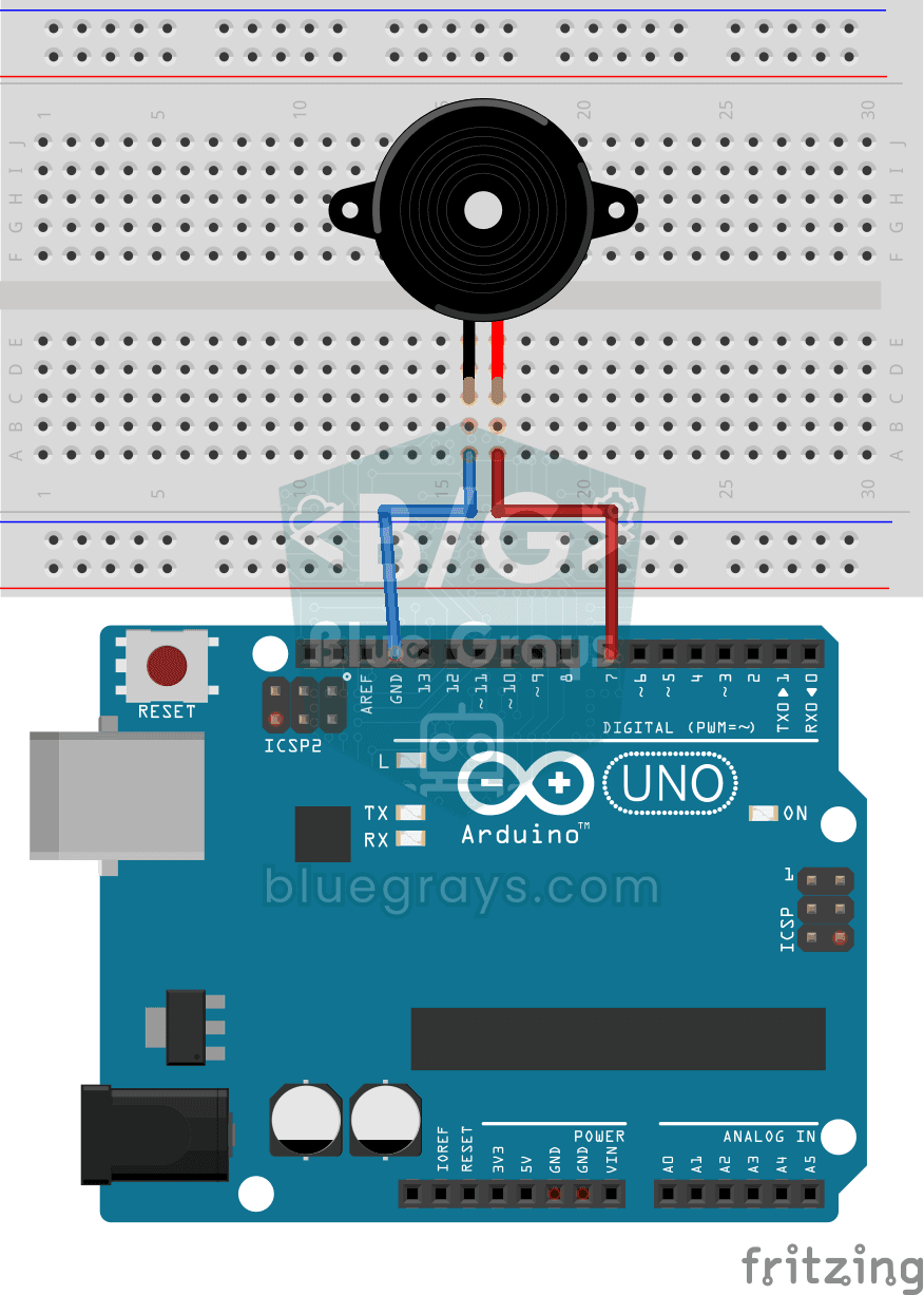
Using a Buzzer
Ever wondered how a doorbell or an alarm makes its sound? The Arduino makes a small buzzer beep at short intervals: beep, pause, beep, pause.
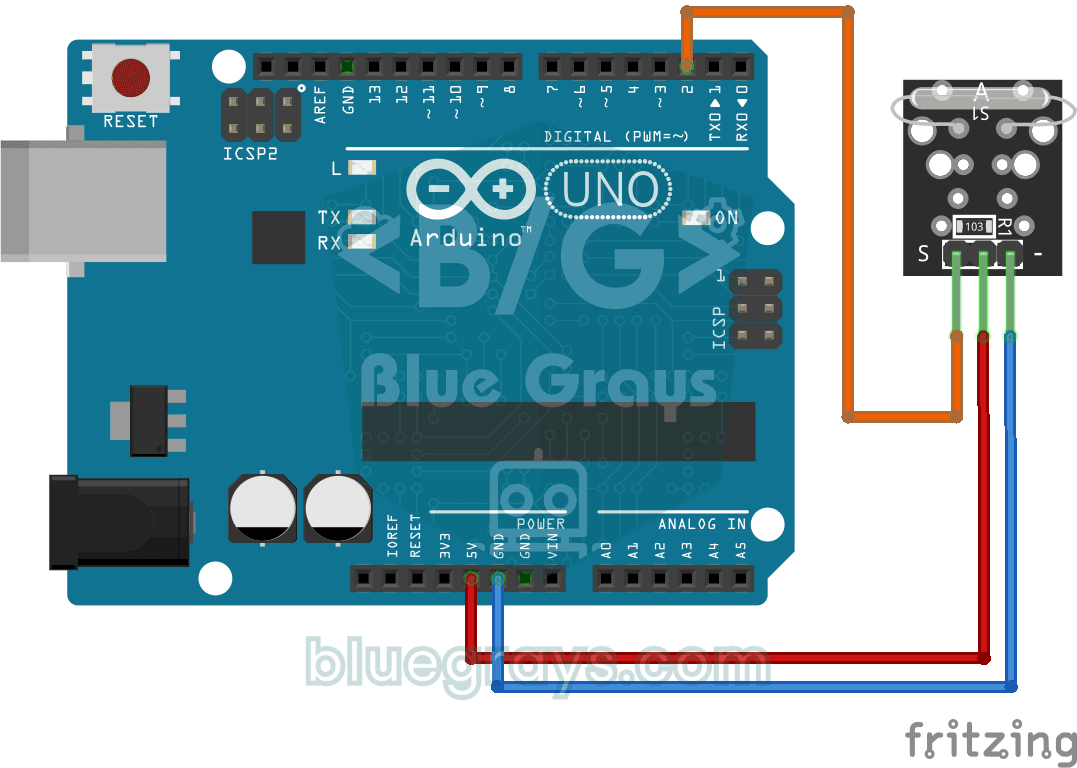
Reading a Reed Switch
Ever wondered about the magnetic switch inside door and window alarms? When a magnet comes near the reed relay module, the tiny switch inside it closes; the Arduino reads it once a second and prints…
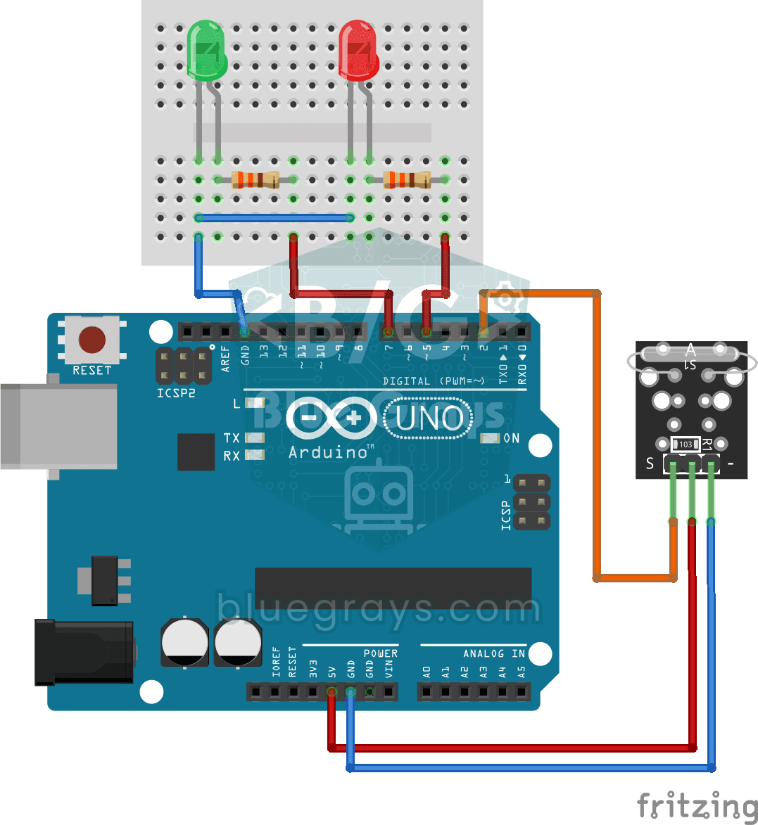
Reed Switch Door Sensor
Tell whether your door is open or closed just by looking at a light. You attach a small magnet to the door and a magnet-sensing switch to the frame; when the door is closed they sit side by side and…

Smart Irrigation Station
A gardener that waters your plants on its own, so they don't dry out while you're on vacation.
Lighting 220V Bulb with Push Button
As long as you hold the button, a real 220-volt bulb stays lit, and it goes out the moment you let go.