
ACS712 Current Sensor: Measure DC and AC Current with Arduino
How to use the ACS712 current sensor: 5A/20A/30A sensitivity, 2.5 V zero point, Arduino DC and AC RMS code, power calculation, ESP32 divider and INA219.
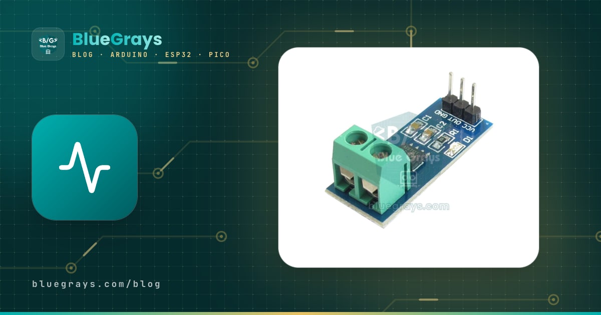
The ACS712 current sensor is a small, cheap module that senses the current flowing through a circuit using the Hall effect and turns it into a voltage your Arduino can read. With no current its output sits at about 2.5 V; it rises as current flows one way and falls as it flows the other way. That means you can measure both direct current (DC) and alternating current (AC) with a single analog pin. It is used to see how much current a motor draws, track a battery as it discharges, detect whether a device is running, or work out how much power an appliance at home consumes. On top of that, the current path being measured is electrically isolated from the Arduino side.
In this guide you will learn step by step what is inside the ACS712, how the 5A, 20A and 30A models differ and which one to choose, how to wire the module in series with your circuit, the first Arduino sketch that measures DC current, how to calm jumpy readings with averaging, how to calculate RMS for AC current, and how to work out power (W) and energy (Wh). After that you will see how to connect it to the 3.3 V ESP32 and Raspberry Pi Pico through a voltage divider, why you must be very careful with mains voltage, and why the INA219 is a better choice for small currents.
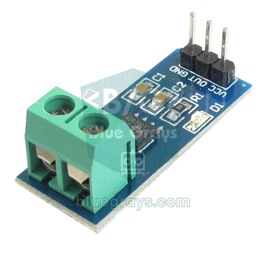
What is the ACS712 current sensor and how does it work?
The ACS712 is an 8-pin chip made by Allegro. The current being measured passes through a thick copper path inside the chip, from pins 1 and 2 to pins 3 and 4. This path has a resistance of only 1.2 mΩ; even at 10 A it drops just 12 mV and dissipates 0.12 W, so it barely affects the circuit you are measuring. As current flows through this conductor it creates a magnetic field proportional to the current. A Hall sensor sitting right above the copper path picks up that field, and an amplifier inside the chip turns it into a voltage. You can read more about the basics in our Hall effect sensors guide.
There is no electrical connection between the copper path carrying the current and the side that powers the chip; the only link between them is the magnetic field. That is why the measured line and the Arduino are isolated from each other (galvanic isolation). The output voltage follows this formula: Vout = VCC / 2 + Sensitivity × I. If current flows from IP+ to IP−, the output rises above 2.5 V; if it flows the other way, the output drops below it. The ACS712 is also ratiometric: both the zero point and the sensitivity scale with the supply voltage. If the supply drops to 4.8 V, the zero point becomes 2.4 V and the sensitivity of the 5A model falls from 185 to about 178 mV/A.
| Parameter | Value |
|---|---|
| Supply voltage | 4.5–5.5 V (typical 5 V) |
| Supply current | Typical 10 mA, max 13 mA |
| Output at zero current | VCC × 0.5 (2.5 V at 5 V) |
| Conductor resistance | 1.2 mΩ |
| Bandwidth | 80 kHz (reduced with the capacitor on the FILTER pin) |
| Total output error | ±1.5% at 25 °C |
| Isolation withstand | 2.4 kV RMS (60 seconds) |
| Output load | At least 4.7 kΩ, at most 10 nF |
| Short overcurrent | 100 A (single pulse, 100 ms) |
| Operating temperature | −40 to 85 °C |
| Module connections | VCC, OUT, GND and a 2-way screw terminal |
5A, 20A and 30A models: sensitivity and resolution
The ACS712 comes in three versions that look exactly the same from the outside. To find out which one you have, read the marking on the chip: ELC-05B measures ±5 A, ELC-20A ±20 A and ELC-30A ±30 A. Sensitivity tells you how many millivolts the output changes for every 1 A of current. The larger the range, the lower the sensitivity, so that on the 20A and 30A models the output stays between 0.5 and 4.5 V even at full current. The table below also shows how many milliamps one step of the Uno's 10-bit ADC (4.88 mV) represents on each model.
| Model (chip marking) | Range | Sensitivity | Output at full range | 1 ADC step on Uno | Noise (47 nF filter) |
|---|---|---|---|---|---|
| ACS712ELCTR-05B | ±5 A | 185 mV/A (180–190) | 1.58–3.43 V | ≈ 26 mA | 21 mV ≈ 0.11 A peak-to-peak |
| ACS712ELCTR-20A | ±20 A | 100 mV/A (96–104) | 0.50–4.50 V | ≈ 49 mA | 11 mV ≈ 0.11 A peak-to-peak |
| ACS712ELCTR-30A | ±30 A | 66 mV/A (63–69) | 0.52–4.48 V | ≈ 74 mA | 7 mV ≈ 0.11 A peak-to-peak |
Two important conclusions follow from the table. First, the noise expressed in amps is about 0.1 A on all three models; if you use the 30A model for a 2 A load, you throw away two thirds of your resolution. The rule is simple: choose the smallest model that safely covers the highest current you will measure (the peak value for AC). For example, the 5A model suits a 12 V DC motor that draws at most 2–3 A, and the 20A model suits a 1500 W heater. Second, the ACS712 is not designed for small currents: you cannot measure an LED drawing a few milliamps or an ESP32 in deep sleep with it. For that job, the INA219 covered at the end of this guide is far better.
ACS712 wiring: Arduino Uno, ESP32 and Pico
The ACS712 module has two sides. The screw terminal side belongs to the circuit being measured: current must enter through one terminal and leave through the other, so the module is connected in series with the load, just like an ammeter. Usually you cut the positive wire of the power supply, connect the end coming from the supply to one side of the terminal and the end going to the load to the other side. The three-pin side goes to the Arduino. The ACS712 only works on 5 V; on the ESP32 and Pico you also power the module from a pin that provides 5 V and read its output through a voltage divider.
| ACS712 pin | Arduino Uno | ESP32 | Raspberry Pi Pico |
|---|---|---|---|
| VCC | 5V | 5V (VIN on some boards) | VBUS (pin 40) |
| OUT | A0 | GPIO 34 (via 10k/20k divider) | GP26 (via 10k/20k divider) |
| GND | GND | GND | GND |
| Screw terminal | In series with the load | In series with the load | In series with the load |
Apart from the chip there are very few parts on the module: a decoupling capacitor on the supply line, a small capacitor on the FILTER pin that sets the bandwidth, the power LED (D1) and its resistor (R1). The 102 printed on R1 means 1 kΩ; you can decode such markings easily with the SMD code calculator. Because the ACS712 is isolated, you do not need to connect the negative of the measured circuit to the Arduino's GND when you are only measuring current.
Step by step: measuring DC current with Arduino
- Connect the module's VCC pin to the Arduino's 5V pin, GND to GND and OUT to A0. The power LED on the board should light up.
- Cut the positive wire of the circuit you want to measure: connect the end coming from the power supply to one side of the terminal and the end going to the load (e.g. a 12 V motor or LED strip) to the other side.
- Keep the load's power supply off and upload the sketch below. At startup it measures the zero point while no current flows.
- Open the Serial Monitor at 9600 baud; with no current the value should stay around 0.00 A and wobble by a few hundredths of an amp at most.
- Switch on the load's power supply. If the current shows up negative, swap the two wires in the terminal or multiply the result by −1.
- Set SENSITIVITY in the code to match your model: 0.185 for 5A, 0.100 for 20A and 0.066 for 30A.
1// ACS712 ile DC akım ölçme / DC current measurement with ACS712
2const int SENSOR_PIN = A0;            // ACS712 OUT pini / ACS712 OUT pin
3const float SENSITIVITY = 0.185;      // V/A: 5A=0.185, 20A=0.100, 30A=0.066
4const float ADC_STEP = 5.0 / 1024.0;  // bir ADC basamağı (V) / one ADC step (V)
5const int SAMPLES = 200;              // ortalama için örnek sayısı / samples to average
6
7float zeroRaw = 512.0;                // akım yokken ham değer / raw value at zero current
8
9// SAMPLES kez okuyup ortalamayı döndürür / reads SAMPLES times and returns the average
10float readAverageRaw() {
11  long sum = 0;
12  for (int i = 0; i < SAMPLES; i++) {
13    sum += analogRead(SENSOR_PIN);
14  }
15  return sum / (float)SAMPLES;
16}
17
18void setup() {
19  Serial.begin(9600);
20  delay(500);                         // sensörün oturmasını bekle / let the sensor settle
21  zeroRaw = readAverageRaw();         // yük KAPALIYKEN sıfır noktası / zero point with the load OFF
22  Serial.print(F("Sifir noktasi / Zero point: "));
23  Serial.print(zeroRaw * ADC_STEP, 3);
24  Serial.println(F(" V"));
25}
26
27void loop() {
28  float raw = readAverageRaw();
29  float current = (raw - zeroRaw) * ADC_STEP / SENSITIVITY;  // amper / amps
30
31  Serial.print(F("Akim / Current: "));
32  Serial.print(current, 2);
33  Serial.println(F(" A"));
34  delay(500);
35}
For each reading the sketch averages 200 analogRead results; since one analogRead takes about 0.11 ms on the Uno, that is roughly 22 ms. The current is found with I = (raw − zero) × (5 / 1024) / sensitivity. For example, on the 5A model with a zero point of 512, an average reading of 550 is a difference of 38 steps; that equals 38 × 4.88 mV = 185.5 mV, so the current is 185.5 / 185 ≈ 1.00 A. Measuring the zero point at startup instead of assuming 2.5 V matters, because the chip's own offset and small differences on the board's ground line shift it by a few steps, and that error is added to every reading.
Noise and averaging
The ACS712 output keeps jittering even when the current is steady. The first reason is the Hall sensor's own noise: the manufacturer quotes the noise figures above with a 47 nF capacitor on the FILTER pin, which means about 2 kHz of bandwidth. Most modules, however, use 1 nF there, as in the manufacturer's example circuit; the bandwidth rises to 80 kHz and the noise is several times higher. The second reason is the ADC: even on the 5A model the Uno measures in 26 mA steps, and the last step always flickers up and down. Random noise shrinks with the square root of the number of averaged samples: 16 samples cut it to a quarter, 256 samples to a sixteenth. For other filtering methods, see our guide on filtering sensor data.
- Multi-sample averaging: For DC, average 100–500 samples. If you spread the samples over 20 ms, 50 Hz interference from the mains also cancels out in the average.
- Exponential moving average: Blend each new reading into the old one with filtered = filtered + 0.1 × (new − filtered); it uses almost no memory and gives a calm value on the display.
- Dead band: If you do not want to see values like 0.03 A with nothing connected, treat results whose absolute value is below 0.05 A as 0.
- Hardware filter: If you can solder, add a 47 nF capacitor in parallel with the one on the FILTER pin to bring the bandwidth down to about 2 kHz; that is more than enough for DC and 50 Hz mains current.
- Keep away from magnetic fields: The ACS712 is a Hall sensor; a nearby magnet, speaker or another wire carrying a large current will shift the reading.
- Refresh the zero point: The zero point drifts a few millivolts with temperature; in long-running projects, measure zero again while the load is off.
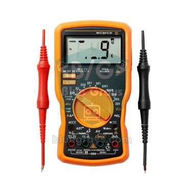
Averaging removes noise but does not fix systematic error. Sensitivity can vary by a few percent from chip to chip; on the 5A model it lies between 180 and 190 mV/A. For the best accuracy, connect a multimeter on its current range in series in the same line as the ACS712, pass a known current such as 1–2 A, and compare the two values. If the multimeter shows 2.00 A and the Arduino 1.94 A, your correction factor is 2.00 / 1.94 = 1.031; divide SENSITIVITY in the code by this number (0.185 / 1.031 ≈ 0.179) and your readings will match the multimeter.
Measuring AC current: the RMS calculation
Mains current keeps changing direction: the frequency is 50 Hz in Europe and most of the world, and 60 Hz in the US. That is why the ACS712 output traces a sine wave around 2.5 V whose average corresponds to zero current; if you run the DC sketch on an AC load, you get meaningless values close to 0 A. The quantity that matters for AC is the RMS (effective) value: it equals the DC current that would produce the same heat, and it is the value used by multimeters, fuses and appliance labels. The calculation follows its name: subtract the zero point from each sample, square it (Square), average the squares (Mean) and take the square root (Root).
The length of the measurement window matters; if it does not contain a whole number of cycles, the result changes a little every time. One cycle lasts 20 ms at 50 Hz and 16.7 ms at 60 Hz. A 100 ms window holds exactly 5 cycles at 50 Hz and exactly 6 at 60 Hz, so it works correctly on both grids, and the Uno takes about 900 samples in that time. For a pure sine wave the peak is 1.414 times the RMS value, so you could also divide the peak by √2. However, loads such as phone chargers, LED bulbs or dimmers draw spiky, non-sinusoidal current, and that shortcut gets them wrong; the sketch below calculates true RMS, so it is much more accurate with such loads. The peak value must stay within the model's range:
| Model | Peak current limit | Max AC current (RMS, sine) | Approx. power at 230 V |
|---|---|---|---|
| 5A | ±5 A | 3.5 A | ≈ 800 W |
| 20A | ±20 A | 14.1 A | ≈ 3250 W |
| 30A | ±30 A | 21.2 A | ≈ 4900 W |
1// ACS712 ile AC akım (RMS) ve görünür güç / AC current (RMS) and apparent power with ACS712
2const int SENSOR_PIN = A0;
3const float SENSITIVITY = 0.100;      // 20A modül: 100 mV/A / 20A module: 100 mV/A
4const float ADC_STEP = 5.0 / 1024.0;
5const unsigned long WINDOW_MS = 100;  // 50 Hz'te 5, 60 Hz'te 6 tam periyot / 5 cycles at 50 Hz, 6 at 60 Hz
6const float MAINS_VOLTAGE = 230.0;    // şebeke gerilimi (V) / mains voltage (V)
7
8float noiseRms = 0.0;                 // yük yokken ölçülen gürültü (A) / noise measured with no load (A)
9
10// Pencere boyunca örnek alır, ortalamayı çıkarıp RMS hesaplar / samples over the window, removes the mean, returns RMS
11float readRmsAmps() {
12  long sum = 0;
13  unsigned long sumSq = 0;
14  unsigned int n = 0;
15  unsigned long start = millis();
16  while (millis() - start < WINDOW_MS) {
17    int d = analogRead(SENSOR_PIN) - 512;  // 2,5 V'u sıfıra yaklaştır / shift 2.5 V to about zero
18    sum += d;
19    sumSq += (long)d * d;
20    n++;
21  }
22  float mean = sum / (float)n;                       // sıfır noktası kayması / zero point offset
23  float variance = sumSq / (float)n - mean * mean;   // yalnız AC kısım / AC part only
24  if (variance < 0) variance = 0;
25  return sqrt(variance) * ADC_STEP / SENSITIVITY;
26}
27
28void setup() {
29  Serial.begin(9600);
30  delay(500);
31  noiseRms = readRmsAmps();           // ilk ölçüm yük KAPALIYKEN / first reading with the load OFF
32  Serial.print(F("Gurultu / Noise: "));
33  Serial.print(noiseRms, 3);
34  Serial.println(F(" A"));
35}
36
37void loop() {
38  float irms = readRmsAmps();
39  float sq = irms * irms - noiseRms * noiseRms;  // gürültüyü karesel çıkar / subtract noise in quadrature
40  irms = (sq > 0) ? sqrt(sq) : 0.0;
41  float apparentPower = MAINS_VOLTAGE * irms;     // VA; dirençli yükte ≈ W / VA; ≈ W for resistive loads
42
43  Serial.print(F("Irms: "));
44  Serial.print(irms, 3);
45  Serial.print(F(" A   Guc / Power: "));
46  Serial.print(apparentPower, 1);
47  Serial.println(F(" VA"));
48  delay(1000);
49}
This sketch does not store the zero point as a fixed number; in every window it finds the average of the samples and subtracts it. Mathematically this is the square root of the variance: RMS² = mean of the squares − square of the mean. Since AC current averages to zero over a whole number of cycles, the average it finds is exactly the zero-point error, and it corrects itself even when that drifts with temperature. The noise measured at startup with the load off is subtracted in quadrature, because noise and the real current are independent and RMS values add by their squares. Without this step you would see ghost values like 0.1 A and 23 VA with nothing connected. An example: a 1000 W iron draws about 4.35 A at 230 V; its peak of 6.1 A exceeds the 5A model's range, so measure it with the 20A model.
A much safer way to measure the current of a household appliance is a split-core current transformer such as the SCT-013, which you use without cutting any wire. It clips around the cable like a clamp meter and never makes metal contact with the mains. The only thing to watch is that the clamp goes around just the live or just the neutral conductor; if you clamp both together, the fields of the opposite currents cancel and the result is zero. Current transformers only measure AC; for DC you need the ACS712 or the INA219.
Calculating power (W) and energy (Wh)
Once you know the current, power is a single multiplication: P = V × I. If a 12 V battery supplies a motor drawing 1.5 A, the power is 12 × 1.5 = 18 W; you can double-check this with the Ohm's law calculator. Energy is power multiplied by time: if the 18 W motor runs for 2 hours, it uses 36 Wh. The sketch does this by multiplying the power by the elapsed time at every reading and adding it up. To measure voltage you can use the module sold as a 0–25 V voltage sensor; it contains a 30 kΩ and 7.5 kΩ voltage divider and divides the input voltage by 5. If you want to design a divider with your own resistor values, use the voltage divider calculator.
1// ACS712 + gerilim sensörü ile güç (W) ve enerji (Wh) / power (W) and energy (Wh) with ACS712 + voltage sensor
2const int CURRENT_PIN = A0;           // ACS712 OUT
3const int VOLTAGE_PIN = A1;           // 0-25 V gerilim sensörü S pini / 0-25 V voltage sensor S pin
4const float SENSITIVITY = 0.185;      // 5A modül / 5A module (V/A)
5const float DIVIDER_RATIO = 5.0;      // (30k + 7,5k) / 7,5k = 5 / divider ratio
6const float ADC_STEP = 5.0 / 1024.0;
7const int SAMPLES = 200;
8
9float zeroRaw = 512.0;
10float energyWh = 0.0;                 // biriken enerji / accumulated energy
11unsigned long lastMs = 0;
12
13float averageRaw(int pin) {
14  long sum = 0;
15  for (int i = 0; i < SAMPLES; i++) sum += analogRead(pin);
16  return sum / (float)SAMPLES;
17}
18
19void setup() {
20  Serial.begin(9600);
21  delay(500);
22  zeroRaw = averageRaw(CURRENT_PIN);  // yük kapalıyken sıfır noktası / zero point with the load off
23  lastMs = millis();
24}
25
26void loop() {
27  float current = (averageRaw(CURRENT_PIN) - zeroRaw) * ADC_STEP / SENSITIVITY;
28  float voltage = averageRaw(VOLTAGE_PIN) * ADC_STEP * DIVIDER_RATIO;
29  float power = voltage * current;    // P = V x I (W)
30
31  unsigned long now = millis();
32  energyWh += power * (now - lastMs) / 3600000.0;  // W x saat = Wh / W x hours = Wh
33  lastMs = now;
34
35  Serial.print(voltage, 2);  Serial.print(F(" V   "));
36  Serial.print(current, 2);  Serial.print(F(" A   "));
37  Serial.print(power, 1);    Serial.print(F(" W   "));
38  Serial.print(energyWh, 3); Serial.println(F(" Wh"));
39  delay(1000);
40}
Since the voltage module connects across the positive and negative of the measured circuit, this time the circuit's negative and the Arduino's GND must be joined; you can find out why in our common ground guide. To estimate how many hours a battery will last, combine the average current you measure with the mAh and Wh calculations or the battery life calculator. On the AC side things are a little different: Vrms × Irms is the apparent power, measured in VA; real power (W) is that multiplied by the power factor. For resistive loads such as kettles, irons and incandescent bulbs, the power factor is very close to 1, so VA ≈ W. For motors, adapters and LED bulbs it can be between 0.5 and 0.9; to measure real power you also need to sample the voltage waveform at the same time, which is done with isolated voltage sensor modules such as the ZMPT101B.
ACS712 with ESP32: reading through a voltage divider
The ESP32 runs on 3.3 V and its analog inputs can measure up to about 3.1 V; applying more than 3.6 V to a pin can damage the board. The ACS712, on the other hand, only works on 5 V, and its output can reach 4.5 V on the 20A and 30A models and almost 5 V under overcurrent. So you power the sensor from the ESP32 board's 5V pin (VIN on some boards) and pass OUT through a voltage divider. 10 kΩ + 20 kΩ is a good choice: go from OUT through 10 kΩ to the ESP32 pin, and from that same point through 20 kΩ to GND. The ratio is 20 / 30 = 0.667, and the total of 30 kΩ easily meets the ACS712's minimum load of 4.7 kΩ.
| ACS712 output | Meaning | Voltage at the ESP32 pin |
|---|---|---|
| 0.50 V | −20 A on the 20A model | 0.33 V |
| 2.50 V | Zero current | 1.67 V |
| 4.50 V | +20 A on the 20A model | 3.00 V |
| 5.00 V | Saturated by overcurrent | 3.33 V |
There are two details in the code. First, the ESP32's ADC is not linear near its ends, so instead of raw values we use analogReadMilliVolts(), which applies the calibration data written into the chip at the factory. GPIO 34 is on ADC1 and works while Wi-Fi is on; ADC2 pins cannot be used together with Wi-Fi. Second, the Uno's ratiometric convenience does not exist here: the ESP32's ADC reference is fixed, but the ACS712's sensitivity changes with the 5 V coming from USB. The fix is a simple trick: since the output equals half of VCC with no current, multiply the zero point measured at startup by 2 to get the sensor's real supply voltage and correct the sensitivity accordingly. Because the same error is present in both the zero point and the measured signal, this method also compensates for the tolerance of the divider resistors. The sketch samples for 100 ms and returns two results together: look at the first number for a DC load and the second for a mains appliance.
1// ESP32 + ACS712 (10k/20k gerilim bölücüyle) / ESP32 + ACS712 (with a 10k/20k voltage divider)
2const int SENSOR_PIN = 34;            // ADC1_CH6, Wi-Fi açıkken de çalışır / works while Wi-Fi is on
3const float DIVIDER = 20.0 / 30.0;    // R2 / (R1 + R2) = 20k / 30k
4const float SENS_AT_5V = 185.0;       // mV/A: 5A=185, 20A=100, 30A=66
5const unsigned long WINDOW_MS = 100;  // 50 Hz'te 5 tam periyot / 5 full cycles at 50 Hz
6
7float zeroMv = 2500.0;                // akım yokken sensör çıkışı (mV) / sensor output at zero current (mV)
8float sensMv = SENS_AT_5V;            // düzeltilmiş hassasiyet (mV/A) / corrected sensitivity (mV/A)
9
10// Bölücüden önceki gerilimin ortalaması (mV) / average voltage before the divider (mV)
11float averageMv(int samples) {
12  uint32_t sum = 0;
13  for (int i = 0; i < samples; i++) sum += analogReadMilliVolts(SENSOR_PIN);
14  return sum / (float)samples / DIVIDER;
15}
16
17// Pencere boyunca okur: DC (ortalama) ve AC (RMS) akım / reads over the window: DC (mean) and AC (RMS) current
18void measure(float &dcAmps, float &acAmps) {
19  double sum = 0, sumSq = 0;
20  uint32_t n = 0;
21  uint32_t start = millis();
22  while (millis() - start < WINDOW_MS) {
23    double d = analogReadMilliVolts(SENSOR_PIN) / DIVIDER - zeroMv;
24    sum += d;
25    sumSq += d * d;
26    n++;
27  }
28  double mean = sum / n;
29  double variance = sumSq / n - mean * mean;
30  if (variance < 0) variance = 0;
31  dcAmps = mean / sensMv;
32  acAmps = sqrt(variance) / sensMv;
33}
34
35void setup() {
36  Serial.begin(115200);
37  analogReadResolution(12);
38  delay(500);
39  zeroMv = averageMv(1000);                    // yük KAPALIYKEN / with the load OFF
40  sensMv = SENS_AT_5V * (2.0 * zeroMv) / 5000.0;  // oransal düzeltme: VCC = 2 x sıfır / ratiometric fix: VCC = 2 x zero
41  Serial.printf("Sifir / Zero: %.0f mV  Hassasiyet / Sensitivity: %.1f mV/A\n", zeroMv, sensMv);
42}
43
44void loop() {
45  float dc, ac;
46  measure(dc, ac);
47  Serial.printf("DC: %.2f A   AC (RMS): %.2f A\n", dc, ac);
48  delay(1000);
49}
ACS712 with Raspberry Pi Pico and MicroPython
The Raspberry Pi Pico also runs on 3.3 V, so the wiring is the same as on the ESP32: connect the ACS712's VCC to VBUS (pin 40), which provides 5 V while the Pico is powered over USB, and OUT through the same 10k/20k divider to GP26 (ADC0, pin 31). In MicroPython, read_u16() returns a value from 0 to 65535, and voltage = raw × 3.3 / 65535. The Pico's ADC is 12-bit; together with the divider, on paper it measures in steps of about 6.5 mA on the 5A model, roughly four times finer than the Uno. The code below measures the zero point at startup, applies the ratiometric correction, and then prints the DC and AC RMS current every second.
1from machine import ADC
2import time
3import math
4
5adc = ADC(26)            # GP26 = ADC0, fiziksel pin 31 / physical pin 31
6VREF = 3.3               # ADC referansı (V) / ADC reference (V)
7DIVIDER = 20 / 30        # 10k/20k bölücü oranı / 10k/20k divider ratio
8SENS_AT_5V = 0.185       # V/A: 5A=0.185, 20A=0.100, 30A=0.066
9
10
11def read_volts(samples=200):
12    # bölücüden önceki ortalama gerilim / average voltage before the divider
13    total = 0
14    for _ in range(samples):
15        total += adc.read_u16()          # 0-65535
16    return total / samples * VREF / 65535 / DIVIDER
17
18
19zero = read_volts(1000)                  # yük KAPALIYKEN / with the load OFF
20sens = SENS_AT_5V * (2 * zero) / 5.0     # oransal düzeltme / ratiometric correction
21print("Sifir / Zero: {:.3f} V".format(zero))
22
23
24def read_rms(window_ms=100):
25    # 100 ms = 50 Hz'te 5 periyot / 5 cycles at 50 Hz
26    n = 0
27    s = 0.0
28    s2 = 0.0
29    start = time.ticks_ms()
30    while time.ticks_diff(time.ticks_ms(), start) < window_ms:
31        v = adc.read_u16() * VREF / 65535 / DIVIDER - zero
32        s += v
33        s2 += v * v
34        n += 1
35    mean = s / n
36    return math.sqrt(max(s2 / n - mean * mean, 0)) / sens
37
38
39while True:
40    dc = (read_volts() - zero) / sens
41    print("DC: {:.2f} A   AC (RMS): {:.2f} A".format(dc, read_rms()))
42    time.sleep(1)
ACS712 or INA219?
The INA219 is a current and voltage monitoring chip made by Texas Instruments that talks over I2C. Instead of the Hall effect, it measures the voltage drop across a small shunt resistor (usually 0.1 Ω on modules) that the current flows through. Popular modules measure up to ±3.2 A with a resolution of about 0.8 mA, read the bus voltage up to 26 V themselves, and calculate power inside the chip. So over a single I2C connection you get voltage, current and power together, with no fiddling with the ADC, averaging or zero calibration. On the other hand, it offers no isolation between the measured circuit and the Arduino, cannot measure AC current and cannot go above 26 V.
| Feature | ACS712 | INA219 module |
|---|---|---|
| Measuring method | Hall effect (magnetic) | Shunt resistor (0.1 Ω) |
| Current range | ±5 / ±20 / ±30 A | ±3.2 A (depends on the shunt) |
| Resolution | 26–74 mA with Uno | ≈ 0.8 mA |
| AC current | Yes | No |
| Voltage and power | No (needs a separate divider) | Yes (up to 26 V) |
| Isolation | Yes | No |
| Interface | Analog output | I2C (address 0x40–0x4F) |
| Supply | 5 V only | 3–5.5 V |
| Best for | Motors, heaters, mains appliances, high current | Batteries, solar panels, sensor and board consumption |
1#include <Wire.h>
2#include <Adafruit_INA219.h>
3
4Adafruit_INA219 ina219;               // varsayılan adres 0x40 / default address 0x40
5
6void setup() {
7  Serial.begin(9600);
8  if (!ina219.begin()) {
9    Serial.println(F("INA219 bulunamadi / INA219 not found"));
10    while (true) delay(10);
11  }
12  // ina219.setCalibration_16V_400mA();  // küçük akımda daha ince çözünürlük / finer resolution for small currents
13}
14
15void loop() {
16  float busV = ina219.getBusVoltage_V();        // yük tarafındaki gerilim / voltage on the load side
17  float current_mA = ina219.getCurrent_mA();    // akım (mA) / current (mA)
18  float power_mW = ina219.getPower_mW();        // güç (mW) / power (mW)
19
20  Serial.print(busV, 2);       Serial.print(F(" V   "));
21  Serial.print(current_mA, 1); Serial.print(F(" mA   "));
22  Serial.print(power_mW, 0);   Serial.println(F(" mW"));
23  delay(1000);
24}
For the code, install the Adafruit INA219 library from the Library Manager. Connect the module's SDA and SCL pins to A4 and A5 on the Uno; the current being measured must enter at VIN+ and leave from VIN− towards the load, and the INA219's GND must be shared with the measured circuit. In short: if you are measuring DC current from a few milliamps up to 3 A along with voltage, choose the INA219; if you need larger currents, AC current or isolation, the ACS712 is the right choice.
ACS712 project ideas
- Motor overcurrent protection: When a DC motor driven by an L298N stalls, its current shoots up; stop the motor and sound an alarm once your threshold is exceeded.
- Battery and solar panel monitor: Measure charge and discharge current with its direction, multiply by voltage, accumulate Wh and show the results on an OLED display.
- Smart plug: Switch the socket with a relay module, use the ACS712 to check whether the appliance is really running and send the data to Home Assistant over MQTT.
- Washing machine finished alert: When the current stays below a set value for a few minutes, let the ESP32 send a message via Telegram.
- Pump dry-run alarm: When the water runs out, the current drawn by the pump drops; detect it and switch the pump off.
- Energy logger: Write current and power once a minute to an SD card or Google Sheets and plot a daily consumption chart.
- Bench power meter: Add an ACS712 to the Arduino voltmeter project to build an instrument that shows voltage, current and power on one screen.
Common mistakes and fixes
| Symptom | Likely cause | Fix |
|---|---|---|
| Shows 0.1–0.3 A with no current | The code assumes a zero point of 2.5 V or 512 | Measure the zero point at startup with the load off and add a small dead band |
| Value keeps jumping | Single-sample reads, wide bandwidth of the 1 nF filter | Average 100–500 samples; add 47 nF to FILTER if needed |
| Current reads negative | Current flows through the terminal the other way | Swap the wires or multiply the result by −1 |
| Values near 0 A on an AC load | DC code used; a sine wave averages to zero | Use the sketch that calculates RMS |
| Values always a few percent high or low | Wrong model value or sensitivity tolerance | Pick 0.185, 0.100 or 0.066 from the chip marking and calibrate with a multimeter |
| Raw value stuck at 0 or 1023 | OUT on the wrong pin or tied to VCC, current beyond the model's range | Check the wiring and use a larger model if needed |
| Power supply shuts down, wire gets hot | Terminal connected in parallel with the supply (short circuit) | Connect the module in series with the load |
| Inconsistent values on ESP32 | No divider, an ADC2 pin or raw analogRead | Use a 10k/20k divider, GPIO 34 and analogReadMilliVolts |
| Reading changes near a magnet | The Hall sensor picks up the external magnetic field | Keep the module away from magnets, speakers and high-current wires |
The ACS712 is a great way to start learning current measurement: with one analog pin you measure DC and AC current, and with a few lines of code you get power and energy as well. If you pick the right model, measure the zero point, average your samples and calibrate with a multimeter, you will get reliable results within a few percent. You can strengthen the basics of analog reading in our ADC guide. In the BlueGrays app you will find projects such as analog sensor reading, a digital voltmeter with an LCD, controlling a mains bulb with a relay and an ESP32 data logger, each with step-by-step circuit diagrams and code.
Frequently asked questions
How many amps can the ACS712 measure, and which model should I choose?
The ACS712 comes in three models measuring ±5 A, ±20 A and ±30 A, with sensitivities of 185, 100 and 66 mV/A. Choose the smallest model that covers the highest current you will measure (the peak value for AC); a smaller model gives a larger output swing and better resolution for the same current. You can tell the model from the ELC-05B, ELC-20A or ELC-30A marking on the chip.
Why does the ACS712 output 2.5 V with no current?
The output starts at half the supply voltage so that the ACS712 can measure current in both directions. When current flows one way the output rises above 2.5 V, and when it flows the other way it drops below. If the supply is not exactly 5 V, the zero point shifts to VCC / 2, which is why measuring it at startup is the best approach.
Can the ACS712 measure mains current?
Yes, the chip has a 2.4 kV RMS isolation withstand rating; at 230 V the 5A model suits loads up to about 800 W and the 20A model up to about 3250 W. However, the module's screw terminal and solder joints sit at mains voltage, so wire it only with the plug pulled, put it in a closed enclosure and do not work alone if you lack experience. A safer option is a clamp-on current transformer such as the SCT-013, which needs no cutting of wires.
Does the ACS712 work with an ESP32 or at 3.3 V?
The ACS712 needs 4.5–5.5 V and does not give correct results on 3.3 V. On the ESP32 and Raspberry Pi Pico, power the module from the 5V, VIN or VBUS pin and connect its output to the analog pin through a 10 kΩ + 20 kΩ voltage divider. That way even an output close to 5 V stays below 3.33 V at the pin.
Why doesn't the ACS712 read zero with no current?
There are two reasons: the code assumes the zero point is exactly 2.5 V or 512, and the sensor has its own noise. Measure the zero point at startup with the load off, average 100–500 samples and add a small dead band such as 0.05 A. For AC, subtracting the noise in quadrature removes the ghost current shown at idle.
ACS712 or INA219: which is better?
It depends on the job. The INA219 works over I2C and gives current, voltage and power together with about 0.8 mA resolution up to ±3.2 A, so it is far more precise for batteries and small DC circuits. The ACS712 measures up to 30 A, also reads AC current and isolates the measured circuit from the Arduino.
Projects to build after reading this
See all projects
Measuring Light Intensity with an LDR
Want to see how bright your room is as a number? The LDR, a small part that reacts to light, measures the light around it, and the Arduino writes the value to your computer screen every half second. C

Reading Light Intensity with the ESP32 LDR Module
Real-time monitoring of the LDR module's raw ADC value and relative light percentage calculated from dark and light reference values in the Serial Monitor. This percentage is not a lux measurement. Teaches the module’s calibration logic. It is ideal to complete this before Project 10, as it is used to determine the threshold value.
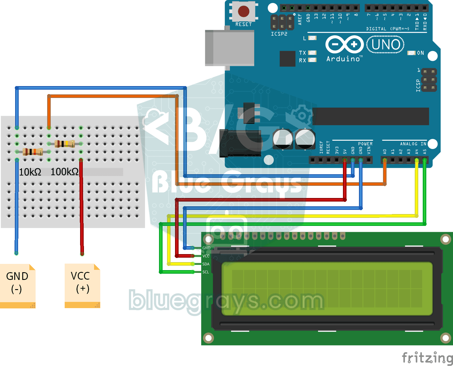
Digital Voltmeter with LCD Display
Find out how much voltage a battery or power adapter gives with a meter you built yourself. A divider made of two resistors brings high voltage down to a level the board can read, and the Arduino calc
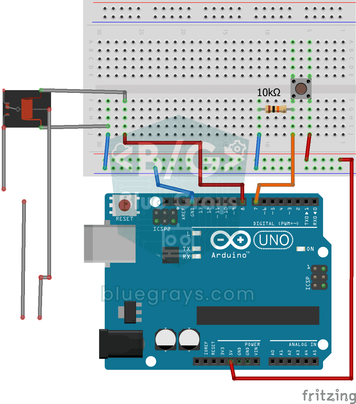
Lighting 220V Bulb with Push Button
As long as you hold the button, a real 220-volt bulb stays lit, and it goes out the moment you let go. The Arduino's tiny signal cannot light the bulb directly, so a relay, an electrically controlled

ESP32 LED Brightness Control with a Potentiometer (Analog → PWM)
In this project, we control the brightness of an LED analogically using a potentiometer. The ESP32's ADC pin reads the 0-3.3V voltage from the potentiometer, and this value is then converted into a PWM (Pulse Width Modulation) signal and sent to the LED. As a result, as you turn the potentiometer, the LED gradually brightens and dims. With Arduino Core 3.0+, analogWrite() can be used directly; on the ESP32-S2/S3, the ADC resolution is fixed at 12-bit.
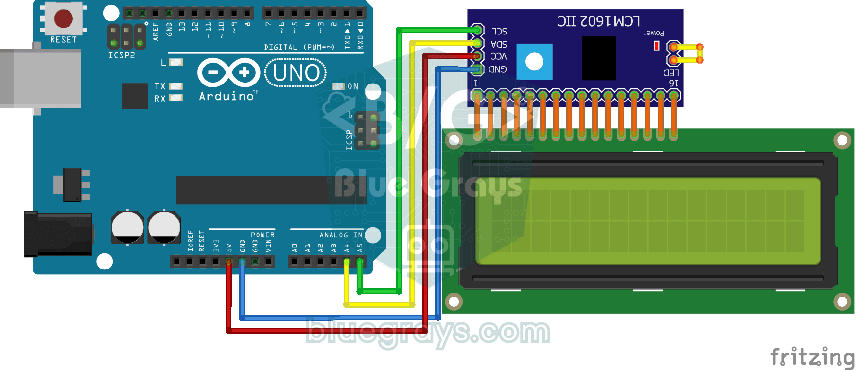
Using LCD Screen with I2C
Give your Arduino its own screen and make it write its first message. The two-line LCD screen hooks up with just a few wires; a greeting appears on the top line, then a second message on the bottom li

ESP32 I2C LCD Display (16x2)
In this project, we display text by connecting a 16x2 character LCD screen to the ESP32 via the I2C protocol. Thanks to I2C, we can control the screen using just two data pins (SDA and SCL), eliminating the waste of 6+ pins associated with a classic parallel connection. The code prints a fixed message on the first line and a counter that increments every second on the second line. Additionally, we run an I2C scanner at the start to print the display’s address to the Serial Monitor (typically 0x2
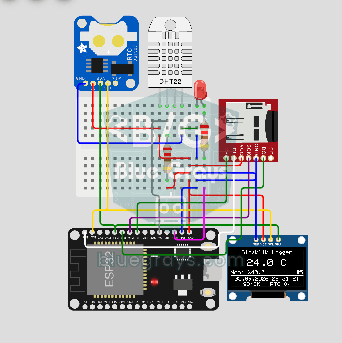
ESP32 Temperature Data Logger (DHT22 + DS1307 RTC + microSD + OLED)
Build a timestamped temperature logger with ESP32! Read DHT22 temperature/humidity every minute, get real-world time from DS1307 RTC, and log to microSD card as CSV. The OLED displays live temperature (large font), humidity percentage, timestamp, and log counter. The /temp_log.csv file on the SD card opens in Excel, Google Sheets, or Python pandas for analysis — perfect for greenhouse monitoring, home/room temperature tracking, laboratory data collection, food storage conditions, or beehiv