
KY-008 Laser Module with Arduino: Laser Tripwire Alarm and Timer
KY-008 laser module and Arduino: wiring, 5 mW 650 nm eye safety, an LDR laser tripwire, automatic threshold calibration, mirrors, a race timer and ESP32 alerts.
A laser module is one of the most eye-catching parts you can use with an Arduino: it produces a thin red beam that travels for metres without spreading out. The KY-008 laser module found in hobby kits packs a 650 nm laser diode of about 5 mW onto a small board; it connects to a single Arduino digital pin and switches on and off with digitalWrite(). On its own it's just a pointer, but put a light sensor opposite it and it becomes a movie-style laser tripwire alarm, a counter for people walking through a door, or a race timer accurate to the millisecond.
In this guide you'll learn the KY-008's specifications, how dangerous a 5 mW laser really is for your eyes and which rules to follow, and how to wire the module correctly to an Arduino Uno, ESP32 and Raspberry Pi Pico. Then you'll build a laser barrier with an LDR, let the Arduino measure the threshold automatically instead of guessing it, turn one laser into several beams with mirrors, count passes and measure speed, and use an ESP32 to send a notification to your phone when the beam is broken.
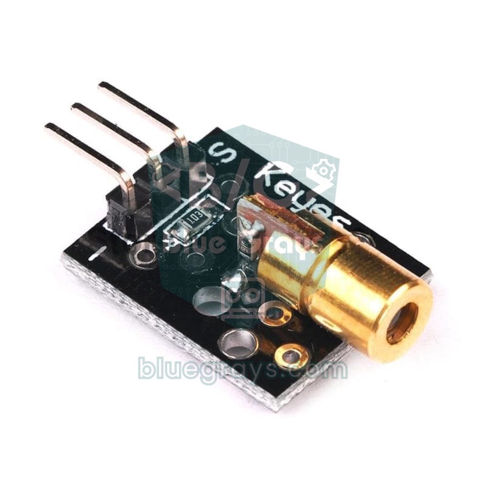
What is the KY-008 laser module and how does it work?
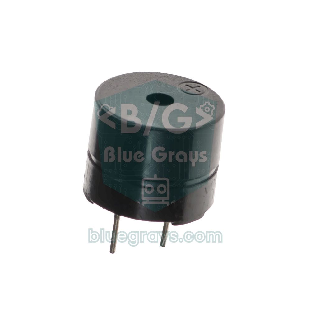
The heart of the module is a small laser diode mounted inside a brass tube. Unlike an ordinary LED, a laser diode emits light at a single wavelength and in an orderly (coherent) way once the current passes a certain threshold; a tiny lens at the end of the tube turns this light into an almost parallel beam. That's why an LED's light spreads out within a few centimetres, while the laser dot stays just a few millimetres across even several metres away. 650 nm is a deep red that the eye sees easily. The resistor on the small board behind the laser head limits the current through the diode. Laser diodes are far more sensitive to overcurrent than LEDs; bypassing this resistor and powering the diode directly can destroy it within seconds.
| Feature | Value |
|---|---|
| Model | KY-008 (sold as HW-493 by some sellers) |
| Wavelength | 650 nm (visible red) |
| Output power | About 5 mW |
| Laser class | 3R (IEC 60825-1), IIIa in the US |
| Operating voltage | 5 V (dimmer at 3.3 V) |
| Current | Below 40 mA; varies from board to board |
| Laser head | 6 mm brass tube |
| Pins | S (signal), middle pin (+5V or unconnected on most boards), − (GND) |
| Operating temperature | −10 to 40 °C |
Eye safety: how dangerous is a 5 mW laser?
A laser's danger doesn't come from its total power but from that power being packed into a tiny spot. The lens of your eye focuses a parallel beam onto a micron-sized point on the retina, so 5 mW that looks harmless on a wall can become a spot on the retina more intense than looking straight at the sun. Lasers are divided into classes according to this risk. With Class 2 lasers below 1 mW, the eye's blink reflex (about 0.25 seconds) usually gives enough protection. Class 3R, where the KY-008 belongs, goes up to five times that limit: a brief accidental glance is low risk, but looking into the beam directly or via a mirror can damage the eye.
| Class | Power (visible light) | Risk |
|---|---|---|
| 1 | Very low, or the beam is enclosed inside the device | Safe in normal use |
| 2 | Up to 1 mW | The blink reflex protects; don't stare on purpose |
| 3R | 1–5 mW (KY-008) | Direct viewing can damage the eye |
| 3B | 5–500 mW | Direct and mirror-reflected beams are dangerous |
| 4 | Above 500 mW | Eye, skin and fire hazard |
- Never look into the beam: Don't bring the laser's output end near your eye, and don't wave the module around in your hand while it's on.
- Keep the beam below eye level: Mount alarm and counter beams 20–50 cm above the floor. That height matches the eye level of a crawling baby, a small child or a cat or dog, so don't leave the laser on while they are around.
- Watch out for reflections: Mirrors, glass, watch faces and shiny metal send the beam in unexpected directions. Check the beam's path from start to finish and end it on a matte, dark surface.
- Children shouldn't use it alone: A laser isn't a toy; work under adult supervision on school and science fair projects.
- Don't blindly trust the label: The real power of cheap modules can differ from the label; treat every module as at least Class 3R.
- Align with a sheet of paper: Hold white paper in front of the beam and follow the dot on the paper; never look into the beam to see where it's going.
KY-008 wiring: Arduino Uno, ESP32 and Raspberry Pi Pico
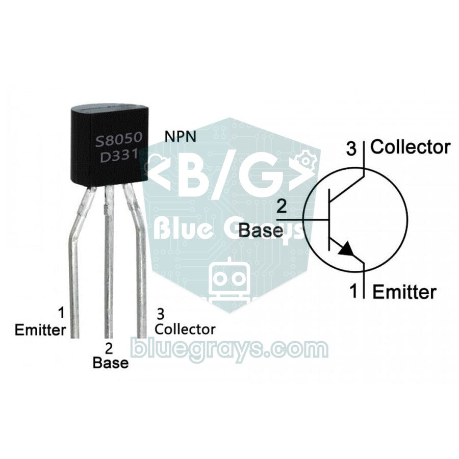
The KY-008 has three pins: S is the signal pin and turns the laser on when HIGH, − is GND, and the unmarked middle pin goes to +5V on most boards or isn't connected at all. The laser sits between S and −, so the Arduino pin you connect to S supplies the laser's current directly. On an Arduino Uno that's fine for short tests, but the module's current varies from board to board and can approach 40 mA. That is the ATmega328P's absolute maximum per pin; the recommended value is 20 mA. If you'll keep the laser on for hours, use more than one laser, or work with an ESP32 or Pico, power the laser from 5V and switch it with an NPN transistor (BC547, S8050 or 2N2222). You can check the transistor's pinout in the transistor guide.
| Connection | Arduino Uno | ESP32 | Raspberry Pi Pico |
|---|---|---|---|
| KY-008 S | D7 | 5V (VIN) | VBUS (pin 40) |
| KY-008 middle pin | Unconnected (5V if the laser won't light) | 5V (VIN) | VBUS (pin 40) |
| KY-008 − | GND | NPN collector | NPN collector |
| NPN emitter | – | GND | GND (pin 38) |
| NPN base (via 1 kΩ) | – | GPIO 26 | GP15 (pin 20) |
| LDR leg 1 | 5V | 3V3 | 3V3(OUT) (pin 36) |
| LDR leg 2 + top of the resistor | A0 | GPIO 34 | GP26 (pin 31) |
| Bottom of the resistor (3.3–10 kΩ) | GND | GND | GND |
| Active buzzer + | D8 | GPIO 25 | GP14 (pin 19) |
Before moving on to the sketches, try the laser and the LDR together with the small test program below. It switches the laser on and off every half second and prints the reading in both states to the Serial Monitor. The bigger the gap between the two values, the more reliable your barrier: on an Uno a gap above 300 is very good; below 100 means the beam isn't hitting the LDR squarely or the ambient light is too strong.
1// KY-008 + LDR ilk test: lazer açıkken ve kapalıyken değerleri gör / First test: see readings with the laser on and off
2const int LASER_PIN = 7;   // KY-008 S pini / KY-008 S pin
3const int LDR_PIN = A0;    // LDR bölücü çıkışı / LDR divider output
4
5void setup() {
6  Serial.begin(9600);
7  pinMode(LASER_PIN, OUTPUT);
8}
9
10void loop() {
11  digitalWrite(LASER_PIN, HIGH);   // lazer açık / laser on
12  delay(500);                      // LDR'nin oturmasını bekle / let the LDR settle
13  int onValue = analogRead(LDR_PIN);
14
15  digitalWrite(LASER_PIN, LOW);    // lazer kapalı / laser off
16  delay(500);
17  int offValue = analogRead(LDR_PIN);
18
19  Serial.print(F("Isin var / beam: "));
20  Serial.print(onValue);
21  Serial.print(F("  Isin yok / no beam: "));
22  Serial.print(offValue);
23  Serial.print(F("  Fark / gap: "));
24  Serial.println(onValue - offValue);
25}
How does an LDR laser barrier work?
The idea behind a laser barrier is simple: the laser beam constantly hits an LDR (light-dependent resistor) on the other side. With the laser dot on it, the LDR's resistance drops to a few hundred ohms; when the beam is broken it rises to tens of kilohms. Wire the LDR with a fixed resistor as a voltage divider and this change in resistance becomes a change in voltage on the analog pin: with 5V → LDR → A0 → resistor → GND, A0 reads high while the beam is there and low when it's broken. The moment someone walks through the beam, the value drops and the Arduino sounds the alarm.
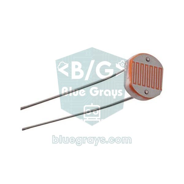
A quick calculation shows why the laser has such a strong effect on the LDR: when the 5 mW beam is concentrated into a dot about 3 mm across, it gives an intensity of roughly 700 W per square metre. That's in the same range as midday sunlight and hundreds of times brighter than a well-lit room. Even so, the barrier's biggest enemy is ambient light: in front of a sunny window the LDR stays bright even when the beam is broken, and the alarm notices nothing. The fix is very cheap: put the LDR at the bottom of a black tube 3–5 cm long (an empty ballpoint pen barrel, a black straw or heat-shrink tubing). The tube only lets in the laser coming from straight ahead and blocks ambient light from the sides.
| Situation | LDR resistance (example) | analogRead with 10 kΩ | analogRead with 3.3 kΩ |
|---|---|---|---|
| Laser on the LDR (inside a tube) | 300 Ω | 993 | 938 |
| Beam broken (inside a tube) | 30 kΩ | 256 | 101 |
| Beam broken (no tube, bright room) | 3 kΩ | 787 | 536 |
| Gap between beam and no beam (inside a tube) | – | 737 | 837 |
Step by step: a laser tripwire alarm with Arduino
- Connect the KY-008's S pin to D7 and its − pin to GND; leave the middle pin unconnected (connect it to 5V if the laser won't light).
- Connect one leg of the LDR to 5V and the other to A0; put a 3.3 kΩ or 10 kΩ resistor between A0 and GND.
- Place the LDR at the bottom of a black tube and point the tube's opening towards the laser.
- Connect the active buzzer's + leg to D8 and its − leg to GND. Fit the silence button between D4 and GND; no extra resistor is needed because the internal pull-up is used.
- Fix the laser and the LDR to a solid base; first find the laser dot with a sheet of white paper, then guide it into the tube.
- Upload the sketch and open the Serial Monitor at 9600 baud. Nobody should be in front of the beam at start-up; the Arduino calibrates itself by switching the laser off and on once.
1// KY-008 lazer + LDR ile lazerli alarm / Laser tripwire alarm with KY-008 + LDR
2const int LASER_PIN = 7;       // KY-008 S pini ya da transistör bazı / KY-008 S pin or transistor base
3const int LDR_PIN = A0;        // LDR bölücü çıkışı / LDR divider output
4const int BUZZER_PIN = 8;      // aktif buzzer / active buzzer
5const int LED_PIN = 13;        // kart üzerindeki LED / on-board LED
6const int RESET_PIN = 4;       // susturma butonu, diğer ucu GND / silence button, other leg to GND
7
8const int BREAK_PCT = 40;                // %40'ın altı = ışın kesik / below 40% = beam broken
9const int RESTORE_PCT = 60;              // %60'ın üstü = ışın sağlam / above 60% = beam intact
10const unsigned long CONFIRM_MS = 30;     // en az bu kadar kesik kalmalı / must stay broken this long
11const unsigned long ALARM_MS = 10000;    // alarm süresi / alarm duration
12
13int onLevel = 0, offLevel = 0;           // ışınlı ve ışınsız ölçüm / reading with and without the beam
14bool beamOk = true;
15bool alarmOn = false;
16unsigned long brokenSince = 0;
17unsigned long alarmStart = 0;
18
19int readAvg() {
20  long sum = 0;
21  for (int i = 0; i < 8; i++) sum += analogRead(LDR_PIN);  // 8 ölçüm ortalaması / average of 8 readings
22  return sum / 8;
23}
24
25void calibrate() {
26  while (true) {
27    digitalWrite(LASER_PIN, LOW);        // lazer kapalı = kesik ışın / laser off = broken beam
28    delay(300);                          // LDR yavaştır, bekle / the LDR is slow, wait
29    offLevel = readAvg();
30    digitalWrite(LASER_PIN, HIGH);       // lazer açık = sağlam ışın / laser on = intact beam
31    delay(300);
32    onLevel = readAvg();
33    Serial.print(F("Isinli / beam: "));
34    Serial.print(onLevel);
35    Serial.print(F("  Isinsiz / no beam: "));
36    Serial.println(offLevel);
37    if (abs(onLevel - offLevel) >= 100) return;   // yeterli fark var / enough difference
38    Serial.println(F("Isin LDR'ye ulasmiyor, hizala! / Beam misses the LDR, align it!"));
39    delay(2000);
40  }
41}
42
43// 100 = ışın tam, 0 = ışın yok; LDR'nin yönü fark etmez / 100 = full beam, 0 = no beam; LDR polarity doesn't matter
44int beamPercent() {
45  return (long)(readAvg() - offLevel) * 100 / (onLevel - offLevel);
46}
47
48void setup() {
49  Serial.begin(9600);
50  pinMode(LASER_PIN, OUTPUT);
51  pinMode(BUZZER_PIN, OUTPUT);
52  pinMode(LED_PIN, OUTPUT);
53  pinMode(RESET_PIN, INPUT_PULLUP);
54  calibrate();
55  Serial.println(F("Alarm hazir / Alarm armed"));
56}
57
58void loop() {
59  unsigned long now = millis();
60  int pct = beamPercent();
61
62  if (beamOk && pct < BREAK_PCT) {       // ışın yeni kesildi / beam just broke
63    beamOk = false;
64    brokenSince = now;
65  } else if (!beamOk && pct > RESTORE_PCT) {
66    beamOk = true;                       // ışın geri geldi / beam restored
67  }
68
69  if (!beamOk && !alarmOn && now - brokenSince >= CONFIRM_MS) {
70    alarmOn = true;
71    alarmStart = now;
72    Serial.println(F("ALARM: isin kesildi! / beam broken!"));
73  }
74
75  if (alarmOn && (now - alarmStart >= ALARM_MS || digitalRead(RESET_PIN) == LOW)) {
76    alarmOn = false;                     // süre doldu ya da butona basıldı / timeout or button pressed
77  }
78
79  digitalWrite(LED_PIN, beamOk ? LOW : HIGH);
80  digitalWrite(BUZZER_PIN, (alarmOn && (now / 200) % 2) ? HIGH : LOW);  // kesik siren / beeping siren
81}
The sketch doesn't use a fixed threshold. At start-up, calibrate() switches the laser off and measures the LDR's value without the beam, then switches it on and measures the value with the beam. beamPercent() converts each reading into a percentage between 0 and 100 based on these two values: 100 means the full beam is arriving, 0 means it's completely blocked. This calculation doesn't care whether the LDR is at the top or the bottom of the divider; the result is the same whether the reading rises or falls with light. If the beam drops below 40% and stays there for at least 30 ms, the alarm beeps for 10 seconds, and the button on D4 silences it early. If the beam is still broken, the alarm starts again, so the system won't go quiet as long as someone stands in the beam.
Threshold calibration: why you shouldn't hard-code a number
Many laser alarm examples online use a fixed threshold such as "analogRead(A0) < 500". That works on the evening you test it at your desk, but it fails the next morning when the sun comes into the room, when you nudge the laser a few millimetres or when you swap the LDR. The right threshold is exactly halfway between the beam and no-beam readings. Automatic calibration, which measures both values again at every start-up, adapts the system to its surroundings. In the sketch above the threshold isn't one number but two: the beam counts as broken when it falls below 40% and as intact when it rises above 60%. This gap is called hysteresis; it stops the alarm switching on and off dozens of times a second when the reading hovers right at the threshold.
| Setting | Value in the code | What does it do? | When should you change it? |
|---|---|---|---|
| BREAK_PCT | 40 | Level at which the beam counts as broken | Raise it to 60–70 to also detect semi-transparent objects (glass, thin fabric) |
| RESTORE_PCT | 60 | Level at which the beam counts as intact again | Always keep it 15–20 points above BREAK_PCT |
| CONFIRM_MS | 30 | Ignores short glitches (insects, dust, vibration) | Raise it to 100–200 ms if you get false alarms; lower it if fast passes are missed |
| Number of readings averaged | 8 | Smooths electrical noise and lamp flicker | Each reading takes about 0.1 ms on an Uno; 8 readings stay under 1 ms |
| Calibration gap | 100 | Stops the setup if the beam doesn't reach the LDR | You can lower it to 50 over very long distances or in very bright rooms |
In a system that runs for a long time, ambient light changes slowly over the day. An easy way to compensate is to call calibrate() again while the beam is intact and the alarm isn't sounding (every hour, for example). Because the Arduino switches the laser off itself, it won't mistake this short darkness for an intruder. The Serial Plotter in the Arduino IDE is very handy for watching the readings: wave your hand through the beam and you'll see how far the graph drops and how long it takes to recover.
Multiple beams with mirrors: weaving a net with one laser
A single beam is easy to get past by ducking under it or stepping over it. To build the laser nets you see in films, instead of giving every beam its own laser and LDR, you can bounce one laser in a zigzag with mirrors. You place mirrors facing each other on both sides of a door or corridor; the beam bounces from side to side and finally reaches the LDR. If any section is broken, the LDR goes dark, so a single LDR and the same sketch protect the whole net. Because the angle of reflection equals the angle of incidence, you only need to tilt each mirror very slightly so it sends the beam to the centre of the next one.
Every mirror loses some of the light. An ordinary bathroom mirror reflects about 90% and produces a faint second dot (a ghost reflection) from the glass in front. Front-surface mirrors, whose reflective layer sits on top of the glass, reflect 95% or more and give a single clean dot. The losses multiply, so the light reaching the LDR falls quickly as you add mirrors:
| Number of mirrors | Ordinary mirror (90%) | Front-surface mirror (95%) |
|---|---|---|
| 1 | 90% | 95% |
| 2 | 81% | 90% |
| 4 | 66% | 81% |
| 6 | 53% | 74% |
| 8 | 43% | 66% |
This table shows something important: even 43% is more than enough for the calibrated sketch, because the laser dot is hundreds of times brighter than ambient light. The real challenge isn't power loss but alignment. The longer the beam's path, the more a small angle error grows: a 1-degree error shifts the dot by about 9 cm at 5 m. The beam of a cheap laser also widens a little along the way; after a few metres the dot can become larger than the LDR's 5 mm surface.
- Mount the laser, the mirrors and the LDR tube on solid holders (screwed L-brackets, 3D-printed holders or wooden blocks fixed with hot glue); a hand-held mirror never stays aligned.
- Dim the room and find the laser dot by holding white paper in front of the first mirror.
- Align the mirrors in order from start to finish: tilt each one very slightly until the dot lands in the centre of the next mirror.
- Aim the last beam into the opening of the LDR tube and run the test sketch to find the position where the gap in the Serial Monitor is largest.
- Once everything is aligned, lock the mirrors' angle with hot glue or a locking screw; even a small knock on the table can ruin the alignment.
- Test every section of the net by breaking it with your hand one by one, and make sure the alarm sounds each time.
Pass counter: how many went through, and for how long?
The same barrier can count people walking through a door, boxes moving along a conveyor or balls dropping into a bin. The trick is to count each pass once. The sketch below records the moment the beam is broken and counts the pass when the beam returns, so someone who stands in the beam for a while still counts as a single pass. Breaks shorter than 15 ms are treated as dust or electrical noise and ignored. The sketch also prints how long the beam was blocked: if you know the object's length, this time gives you its speed directly (v = L / t). For example, if a 25 cm toy car blocks the beam for 50 ms, its speed is 0.25 / 0.05 = 5 m/s.
1// Lazer bariyeriyle geçiş sayacı ve kesilme süresi / Laser barrier pass counter and block time
2const int LASER_PIN = 7;                 // KY-008 S pini / KY-008 S pin
3const int LDR_PIN = A0;                  // LDR bölücü çıkışı / LDR divider output
4const unsigned long MIN_BREAK_MS = 15;   // daha kısa kesintiler parazittir / shorter breaks are noise
5const float OBJECT_LENGTH_M = 0.0;       // cismin boyu biliniyorsa yaz (ör. 0.25) / object length if known (e.g. 0.25)
6
7int onLevel = 0, offLevel = 0;
8bool beamOk = true;
9unsigned long brokenSince = 0;
10unsigned long passCount = 0;
11
12int readAvg() {
13  long sum = 0;
14  for (int i = 0; i < 4; i++) sum += analogRead(LDR_PIN);  // 4 ölçüm yeterli ve hızlı / 4 readings: enough and fast
15  return sum / 4;
16}
17
18void calibrate() {
19  while (true) {
20    digitalWrite(LASER_PIN, LOW);
21    delay(300);
22    offLevel = readAvg();
23    digitalWrite(LASER_PIN, HIGH);
24    delay(300);
25    onLevel = readAvg();
26    if (abs(onLevel - offLevel) >= 100) return;
27    Serial.println(F("Isin LDR'ye ulasmiyor / Beam misses the LDR"));
28    delay(2000);
29  }
30}
31
32int beamPercent() {
33  return (long)(readAvg() - offLevel) * 100 / (onLevel - offLevel);
34}
35
36void setup() {
37  Serial.begin(9600);
38  pinMode(LASER_PIN, OUTPUT);
39  calibrate();
40  Serial.println(F("Sayac hazir / Counter ready"));
41}
42
43void loop() {
44  unsigned long now = millis();
45  int pct = beamPercent();
46
47  if (beamOk && pct < 40) {
48    beamOk = false;
49    brokenSince = now;                   // kesilme anı / moment of the break
50  } else if (!beamOk && pct > 60) {
51    beamOk = true;
52    unsigned long blocked = now - brokenSince;   // ışın ne kadar kesik kaldı / how long the beam was blocked
53    if (blocked >= MIN_BREAK_MS) {
54      passCount++;
55      Serial.print(F("Gecis / Pass #"));
56      Serial.print(passCount);
57      Serial.print(F("  Sure / Time: "));
58      Serial.print(blocked);
59      Serial.print(F(" ms"));
60      if (OBJECT_LENGTH_M > 0) {
61        float speed = OBJECT_LENGTH_M / (blocked / 1000.0);  // v = L / t
62        Serial.print(F("  Hiz / Speed: "));
63        Serial.print(speed, 2);
64        Serial.print(F(" m/s"));
65      }
66      Serial.println();
67    }
68  }
69}
If you want to know which way someone passes, use two parallel beams 10–15 cm apart. If the outer beam A breaks first and then the inner beam B, the person is coming in; if B breaks first and then A, they're going out. If only A breaks and the beam returns without B ever breaking, the person approached the door and changed their mind, so it isn't counted. You get the number of people inside by subtracting exits from entries, and you can show it on a 7-segment display or an I2C LCD display. The gap between the two beams should be narrow enough for a person's body to block both at the same moment.
Race timer and speed measurement
Measuring the time between two laser gates gives you a precise stopwatch for running, cycling, toy cars or physics experiments. You set up the start and finish gates a known distance (d) apart, and the speed is v = d / t. Someone who runs a 10 m track in 2.5 seconds is running at 4 m per second, or 14.4 km/h. To switch both lasers on and off together, connect the − pin of each to the collector of a single 2N2222 or S8050 transistor; wire the S and middle pins to 5V, the transistor's emitter to GND and its base to D7 through 1 kΩ. The start gate's LDR goes to A0 and the finish gate's to A1.
1// İki lazer kapılı yarış zamanlayıcı ve hız ölçer / Two-gate laser race timer and speed meter
2const int LASER_PIN = 7;                 // iki lazer tek transistörle / both lasers through one transistor
3const int START_LDR = A0;                // başlangıç kapısı / start gate
4const int FINISH_LDR = A1;               // bitiş kapısı / finish gate
5const int BUZZER_PIN = 8;                // aktif buzzer / active buzzer
6const float DISTANCE_M = 10.0;           // kapılar arası mesafe (metre) / distance between the gates (m)
7const unsigned long TIMEOUT_MS = 60000;  // 60 sn'de bitmezse iptal / cancel after 60 s
8
9int onA, offA, onB, offB;
10enum State { READY, RUNNING, DONE };
11State state = READY;
12unsigned long startUs = 0;
13unsigned long startMs = 0;
14unsigned long doneMs = 0;
15
16int readAvg(int pin) {
17  long sum = 0;
18  for (int i = 0; i < 4; i++) sum += analogRead(pin);
19  return sum / 4;
20}
21
22bool isBroken(int pin, int on, int off) {
23  long pct = (long)(readAvg(pin) - off) * 100 / (on - off);
24  return pct < 40;                       // %40'ın altı = kesik / below 40% = broken
25}
26
27void calibrate() {
28  while (true) {
29    digitalWrite(LASER_PIN, LOW);        // iki lazer de kapalı / both lasers off
30    delay(300);
31    offA = readAvg(START_LDR);
32    offB = readAvg(FINISH_LDR);
33    digitalWrite(LASER_PIN, HIGH);       // iki lazer de açık / both lasers on
34    delay(300);
35    onA = readAvg(START_LDR);
36    onB = readAvg(FINISH_LDR);
37    if (abs(onA - offA) >= 100 && abs(onB - offB) >= 100) return;
38    Serial.println(F("Kapilardan biri hizali degil / One gate is misaligned"));
39    delay(2000);
40  }
41}
42
43void beep(int ms) {
44  digitalWrite(BUZZER_PIN, HIGH);
45  delay(ms);
46  digitalWrite(BUZZER_PIN, LOW);
47}
48
49void setup() {
50  Serial.begin(9600);
51  pinMode(LASER_PIN, OUTPUT);
52  pinMode(BUZZER_PIN, OUTPUT);
53  calibrate();
54  Serial.println(F("Hazir: baslangic kapisini gec / Ready: cross the start gate"));
55}
56
57void loop() {
58  if (state == READY && isBroken(START_LDR, onA, offA)) {
59    startUs = micros();                  // zamanı hemen al / grab the time immediately
60    startMs = millis();
61    state = RUNNING;
62    beep(30);
63  } else if (state == RUNNING) {
64    if (isBroken(FINISH_LDR, onB, offB)) {
65      unsigned long elapsedUs = micros() - startUs;
66      float seconds = elapsedUs / 1000000.0;
67      float speed = DISTANCE_M / seconds;            // v = d / t
68      Serial.print(F("Sure / Time: "));
69      Serial.print(seconds, 3);
70      Serial.print(F(" s  Hiz / Speed: "));
71      Serial.print(speed, 2);
72      Serial.print(F(" m/s = "));
73      Serial.print(speed * 3.6, 1);
74      Serial.println(F(" km/h"));
75      beep(300);
76      state = DONE;
77      doneMs = millis();
78    } else if (millis() - startMs > TIMEOUT_MS) {
79      Serial.println(F("Zaman asimi / Timeout"));
80      state = READY;
81    }
82  } else if (state == DONE && millis() - doneMs > 3000 &&
83             !isBroken(START_LDR, onA, offA) && !isBroken(FINISH_LDR, onB, offB)) {
84    state = READY;                       // 3 sn sonra yeni tur / new run after 3 s
85    Serial.println(F("Hazir / Ready"));
86  }
87}
The sketch works like a state machine: in the READY state it records the time with micros() when the start beam is broken and moves to RUNNING; when the finish beam is broken it prints the elapsed time and speed, and after 3 seconds it gets ready for the next run. If the finish gate isn't crossed within 60 seconds, the run is cancelled. To be honest about accuracy: the code itself measures with better than 1 ms resolution, but the LDR takes 10–30 ms to respond to darkness. Fortunately, since you use the same type of LDR at both gates, this delay happens at both ends and largely cancels out; for running and cycling the result is more than good enough.
Phone notifications with an ESP32 (Telegram)
To make the alarm useful when you're not at home, you can use an ESP32: the moment the beam is broken it sends a message to your phone through Telegram. The wiring is as in the table above: the laser is powered from 5V and switched by an NPN transistor connected to GPIO 26, and the LDR divider is fed from 3V3 and connected to GPIO 34. That choice isn't random: the ESP32's ADC2 pins don't work while Wi-Fi is on, so always connect analog sensors to ADC1 pins (GPIO 32–39). The ESP32's ADC is 12-bit and returns values from 0 to 4095, which is why the minimum calibration gap in the code is 400. We covered creating the bot and getting the token and chat ID in detail in the ESP32 Telegram bot guide; for the sketch, install the UniversalTelegramBot and ArduinoJson libraries from the Library Manager.
1// ESP32 lazer bariyeri + Telegram bildirimi / ESP32 laser tripwire + Telegram notification
2#include <WiFi.h>
3#include <WiFiClientSecure.h>
4#include <UniversalTelegramBot.h>        // ArduinoJson kütüphanesi de gerekir / also needs the ArduinoJson library
5
6const char* WIFI_SSID = "WIFI_ADI";      // Wi-Fi ağının adı / your Wi-Fi name
7const char* WIFI_PASS = "WIFI_SIFRESI";  // Wi-Fi şifren / your Wi-Fi password
8#define BOT_TOKEN "1234567890:ABCdefGhIJKlmNoPQRstuVWXyz"  // BotFather'dan / from BotFather
9#define CHAT_ID "123456789"              // senin chat ID'n / your chat ID
10
11const int LASER_PIN = 26;                // NPN transistör bazına 1 kΩ ile / to the NPN base via 1 kΩ
12const int LDR_PIN = 34;                  // ADC1 pini, Wi-Fi ile çalışır / ADC1 pin, works with Wi-Fi
13const int BUZZER_PIN = 25;               // aktif buzzer / active buzzer
14const unsigned long CONFIRM_MS = 30;     // en az bu kadar kesik kalmalı / must stay broken this long
15const unsigned long SIREN_MS = 5000;     // siren süresi / siren duration
16const unsigned long COOLDOWN_MS = 30000; // iki deneme arası en az 30 sn / at least 30 s between attempts
17
18WiFiClientSecure client;
19UniversalTelegramBot bot(BOT_TOKEN, client);
20
21int onLevel = 0, offLevel = 0;
22bool beamOk = true;
23bool counted = false;                    // bu kesinti sayıldı mı / has this break been counted
24unsigned long brokenSince = 0;
25bool sirenOn = false;
26unsigned long sirenStart = 0;
27unsigned long breakCount = 0;
28bool pending = false;                    // gönderilecek bildirim var / a notification is waiting
29bool triedOnce = false;
30unsigned long lastTry = 0;
31
32int readAvg() {
33  long sum = 0;
34  for (int i = 0; i < 16; i++) sum += analogRead(LDR_PIN);  // 16 ölçüm ortalaması / average of 16 readings
35  return sum / 16;
36}
37
38void calibrate() {
39  while (true) {
40    digitalWrite(LASER_PIN, LOW);        // lazer kapalı = kesik ışın / laser off = broken beam
41    delay(300);
42    offLevel = readAvg();
43    digitalWrite(LASER_PIN, HIGH);       // lazer açık = sağlam ışın / laser on = intact beam
44    delay(300);
45    onLevel = readAvg();
46    Serial.printf("Isinli / beam: %d  Isinsiz / no beam: %d\n", onLevel, offLevel);
47    if (abs(onLevel - offLevel) >= 400) return;   // 12 bit ölçekte yeterli fark / enough gap on the 12-bit scale
48    Serial.println("Isin LDR'ye ulasmiyor / Beam misses the LDR");
49    delay(2000);
50  }
51}
52
53int beamPercent() {
54  return (long)(readAvg() - offLevel) * 100 / (onLevel - offLevel);
55}
56
57void setup() {
58  Serial.begin(115200);
59  pinMode(LASER_PIN, OUTPUT);
60  pinMode(BUZZER_PIN, OUTPUT);
61  calibrate();
62
63  WiFi.mode(WIFI_STA);
64  WiFi.begin(WIFI_SSID, WIFI_PASS);
65  client.setCACert(TELEGRAM_CERTIFICATE_ROOT);    // api.telegram.org kök sertifikası / root certificate
66  unsigned long start = millis();
67  while (WiFi.status() != WL_CONNECTED && millis() - start < 15000) {  // en fazla 15 sn bekle / wait up to 15 s
68    delay(500);
69    Serial.print(".");
70  }
71  if (WiFi.status() == WL_CONNECTED) {
72    Serial.println(WiFi.localIP());
73    bot.sendMessage(CHAT_ID, "Lazer alarmi devrede / Laser alarm armed", "");
74  }
75}
76
77void loop() {
78  unsigned long now = millis();
79  int pct = beamPercent();
80
81  if (beamOk && pct < 40) {              // ışın yeni kesildi / beam just broke
82    beamOk = false;
83    counted = false;
84    brokenSince = now;
85  } else if (!beamOk && pct > 60) {
86    beamOk = true;                       // ışın geri geldi / beam restored
87  }
88
89  if (!beamOk && !counted && now - brokenSince >= CONFIRM_MS) {
90    counted = true;                      // her kesinti bir kez sayılır / each break counts once
91    breakCount++;
92    pending = true;
93    sirenOn = true;
94    sirenStart = now;
95    Serial.printf("Kesinti / Break #%lu\n", breakCount);
96  }
97
98  if (sirenOn && now - sirenStart >= SIREN_MS) sirenOn = false;
99  digitalWrite(BUZZER_PIN, (sirenOn && (now / 200) % 2) ? HIGH : LOW);  // kesik siren / beeping siren
100
101  if (pending && (!triedOnce || now - lastTry >= COOLDOWN_MS)) {
102    triedOnce = true;
103    lastTry = now;
104    if (WiFi.status() == WL_CONNECTED) {
105      String text = "Lazer bariyeri kesildi! / Laser beam broken! Toplam / Total: " + String(breakCount);
106      if (bot.sendMessage(CHAT_ID, text, "")) pending = false;  // gitmezse 30 sn sonra yeniden / retry in 30 s if it fails
107    } else {
108      WiFi.reconnect();                  // bağlantı koptuysa yeniden dene / reconnect if the link dropped
109    }
110  }
111}
Each break is counted once, the siren sounds for 5 seconds and a notification is queued. Notifications are attempted at most once every 30 seconds; new breaks that happen in the meantime are added to the total and appear in the next message. That way your phone isn't flooded with messages while someone walks back and forth through the beam. If a message can't be sent, the code tries again 30 seconds later, and if Wi-Fi has dropped it starts reconnecting. sendMessage() takes a second or two because it opens a secure HTTPS connection; during that time the siren pattern freezes and the beam isn't monitored, which is normal.
Laser barrier with Raspberry Pi Pico and MicroPython
On the Raspberry Pi Pico you can build the same logic in a few lines of MicroPython. The laser is powered from VBUS (USB 5 V, pin 40) and switched by an NPN transistor connected to GP15; the LDR divider is fed from the 3V3(OUT) pin and connected to GP26 (ADC0), and the active buzzer goes to GP14. Because the Pico's ADC returns values from 0 to 65535 with read_u16(), the minimum calibration gap is 6000. The code uses the same percentage calculation, hysteresis and confirmation time; it counts every break, sounds the siren for 5 seconds and prints how long the beam was blocked. To make the Pico run without a computer, save the file to the board as main.py using Thonny.
1# Raspberry Pi Pico lazer bariyeri: alarm + geçiş sayacı / Laser barrier: alarm + pass counter
2from machine import Pin, ADC
3import time
4
5laser = Pin(15, Pin.OUT)        # NPN transistör bazına 1 kΩ ile / to the NPN base via 1 kΩ
6ldr = ADC(26)                   # GP26 = ADC0, bölücü 3V3'ten / divider fed from 3V3
7buzzer = Pin(14, Pin.OUT)       # aktif buzzer / active buzzer
8
9CONFIRM_MS = 30                 # en az bu kadar kesik kalmalı / must stay broken this long
10SIREN_MS = 5000                 # siren süresi / siren duration
11
12
13def read_avg(n=8):
14    total = 0
15    for _ in range(n):
16        total += ldr.read_u16()
17    return total // n
18
19
20def calibrate():
21    while True:
22        laser.value(0)          # lazer kapalı = kesik ışın / laser off = broken beam
23        time.sleep_ms(300)
24        off = read_avg(32)
25        laser.value(1)          # lazer açık = sağlam ışın / laser on = intact beam
26        time.sleep_ms(300)
27        on = read_avg(32)
28        print("Isinli / beam:", on, " Isinsiz / no beam:", off)
29        if abs(on - off) > 6000:          # 16 bit ölçekte yeterli fark / enough gap on the 16-bit scale
30            return on, off
31        print("Isin LDR'ye ulasmiyor / Beam misses the LDR")
32        time.sleep(2)
33
34
35on_level, off_level = calibrate()
36beam_ok = True
37counted = False
38broken_at = time.ticks_ms()
39siren_until = time.ticks_ms()
40count = 0
41
42while True:
43    now = time.ticks_ms()
44    pct = (read_avg() - off_level) * 100 // (on_level - off_level)   # 100 = ışın tam / full beam
45
46    if beam_ok and pct < 40:            # ışın yeni kesildi / beam just broke
47        beam_ok = False
48        counted = False
49        broken_at = now
50    elif not beam_ok and pct > 60:      # ışın geri geldi / beam restored
51        beam_ok = True
52        print("Kesik kaldigi sure / blocked for", time.ticks_diff(now, broken_at), "ms")
53
54    if not beam_ok and not counted and time.ticks_diff(now, broken_at) >= CONFIRM_MS:
55        counted = True                  # her kesinti bir kez sayılır / each break counts once
56        count += 1
57        siren_until = time.ticks_add(now, SIREN_MS)
58        print("Gecis / Pass:", count)
59
60    siren = time.ticks_diff(siren_until, now) > 0
61    buzzer.value(1 if siren and (now // 200) % 2 else 0)   # kesik siren / beeping siren
Laser module project ideas
- Laser home alarm: Combine door and corridor beams with a PIR motion sensor and bring all the inputs into one control unit; details in the Arduino alarm system guide.
- Laser harp: Set up 5–7 beams side by side and play a different note on a passive buzzer whenever a beam is broken.
- Visitor counter: Separate entries and exits with two beams and show the number of people inside on a display.
- Science fair speed meter: Use two gates to measure the speed of objects sliding down a ramp and compare friction; for more ideas see the science fair project ideas guide.
- Laser maze game: Build a net of beams with mirrors below knee height; time players trying to cross without touching it and add a penalty for every touch.
- Drawer and safe protection: Detect the beam being broken when the lid opens and send a notification to your phone with an ESP32.
Common mistakes and how to fix them
| Symptom | Likely cause | Fix |
|---|---|---|
| The laser doesn't light at all | S and − swapped, or a board whose middle pin needs power | Check the pin labels, connect the middle pin to 5V and try again |
| The laser is very dim | The module is fed from 3.3 V or the pin can't supply enough current | Power the laser from 5V and switch it with a transistor |
| "Isin LDR'ye ulasmiyor" (beam misses the LDR) message | The dot isn't on the LDR or the ambient light is too strong | Find the dot with paper and put the LDR in a black tube |
| The alarm keeps sounding | The alignment has drifted, the laser or a mirror is wobbling | Fix the holders firmly and watch the reading in the Serial Plotter |
| The alarm never sounds | Even with the beam broken, sunlight or a lamp keeps the LDR lit | Add a tube and turn the sensor away from the window |
| Fast passes aren't counted | The LDR's response time (10–30 ms) is too slow | Lower CONFIRM_MS and MIN_BREAK_MS or use a phototransistor |
| The Arduino resets or a pin gets hot | Several lasers are driven from one pin | Power the lasers from 5V and switch them with a transistor |
| On the ESP32 the reading goes wrong when Wi-Fi starts | The LDR is on an ADC2 pin | Move the LDR to an ADC1 pin between GPIO 32 and 39 |
| No Telegram message arrives | Wrong token or chat ID, or you never messaged the bot | Send /start to the bot and check the token and chat ID again |
The KY-008 laser module makes possible one of the rare projects that teaches optics, voltage dividers, calibration and time measurement all at once with a single cheap part. Start by seeing the gap with the test sketch, then build the alarm, and grow your project with mirrors, a counter and a timer. In the BlueGrays app you'll find the laser warning and security system, LDR light measurement and night light, the ESP32 motion alarm and Telegram notification projects step by step, with circuit diagrams and code.
Frequently asked questions
What voltage does the KY-008 laser module need?
The KY-008 is designed for 5 V, and thanks to the module's current-limiting resistor it can be connected directly to an Arduino Uno digital pin. It also lights at 3.3 V, but more dimly. Never feed the module more than 5 V, and never power the laser diode without its resistor.
Can a 5 mW laser damage your eyes?
A 5 mW red laser is Class 3R: a brief, accidental exposure usually doesn't cause lasting damage, but staring into the beam or catching a mirror reflection in your eye can harm the retina. Keep the beam below eye level, never point it at people or animals, and check the whole beam path in mirror setups.
How far does a laser tripwire work?
Alignment and ambient light limit the distance more than the laser's power does. With solid holders and an LDR inside a black tube, it works fine over 10–20 m indoors; at longer distances the dot grows and less light falls on the LDR. Outdoors, sunlight, fog and wind-induced shaking reduce the range noticeably.
What can I use instead of an LDR in a laser barrier?
An LDR is cheap and easy, but its response time is 10–30 ms. For timers and counters that need faster measurement, a phototransistor or photodiode, which responds within microseconds, is used. Ready-made laser receiver modules also exist; they give a digital output when they receive light and connect straight to a digital pin.
Does the laser module work with ESP32 and Raspberry Pi Pico?
Yes, but rather than powering the laser straight from a pin, it's better to feed it from 5V and switch it with an NPN transistor; Pico pins only supply 4 mA by default. On these boards feed the LDR divider from 3V3, and on the ESP32 use an ADC1 pin (GPIO 32–39), which works alongside Wi-Fi.
Is an infrared beam barrier better than a laser alarm?
Professional security systems use invisible infrared beams and modulated receivers; the beam can't be spotted and the modulation makes it barely affected by sunlight. A red laser, on the other hand, is visible and therefore very easy to align, which makes it ideal for learning projects, counters and timers.
Projects to build after reading this
See all projects
Measuring Light Intensity with an LDR
Want to see how bright your room is as a number? The LDR, a small part that reacts to light, measures the light around it, and the Arduino writes the value to your computer screen every half second. C

Night Light with Ldr
A little night light that turns on by itself when it gets dark and goes off when morning comes. A light sensor measures how bright the room is, and the Arduino switches the LED on when it is dark enou

Reading Light Intensity with the ESP32 LDR Module
Real-time monitoring of the LDR module's raw ADC value and relative light percentage calculated from dark and light reference values in the Serial Monitor. This percentage is not a lux measurement. Teaches the module’s calibration logic. It is ideal to complete this before Project 10, as it is used to determine the threshold value.
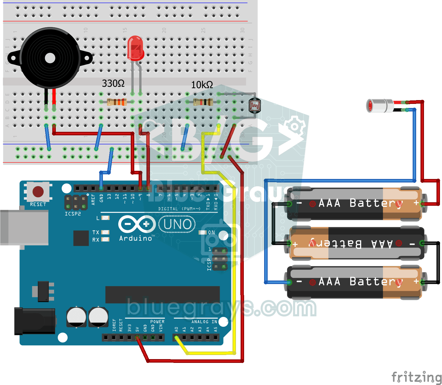
Laser Warning System
You set up an invisible beam fence, just like in the movies. A laser shines onto a light sensor on the other side; the moment someone walks through and breaks the beam, the LED lights up and the buzze
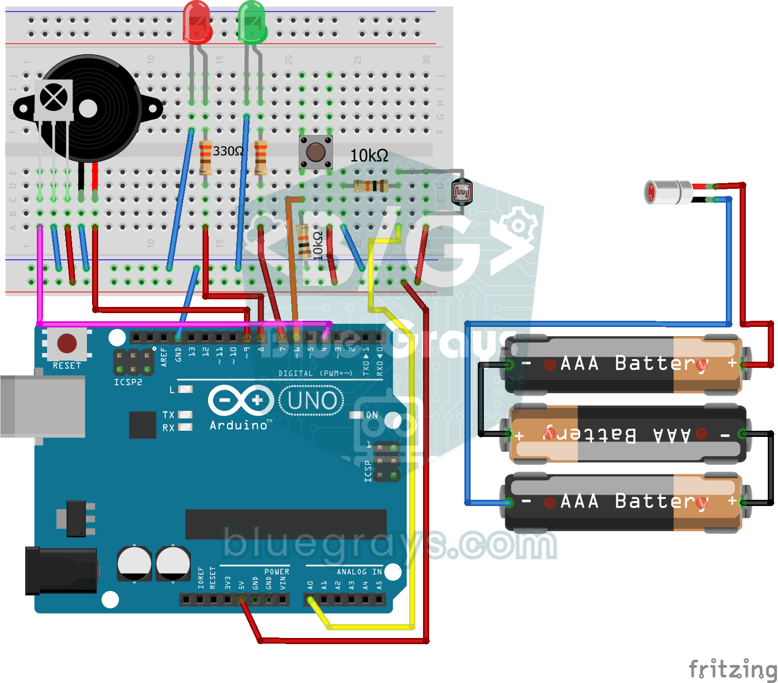
Laser Security System
Just like the laser heist scenes in films: a laser beam shines on a light sensor, and the moment someone steps in and breaks the beam, the red LED lights up and the buzzer starts sounding. The alarm d

ESP32 Night Light with LDR
Night light where the LED automatically turns on in the dark and off in the light. The D0 (digital out) pin of the LDR Sensor Module is used - the dark threshold is set with the small potentiometer on the module, the module itself generates the HIGH/LOW output. ESP32 just reads this signal with digitalRead(), the code is very simple.
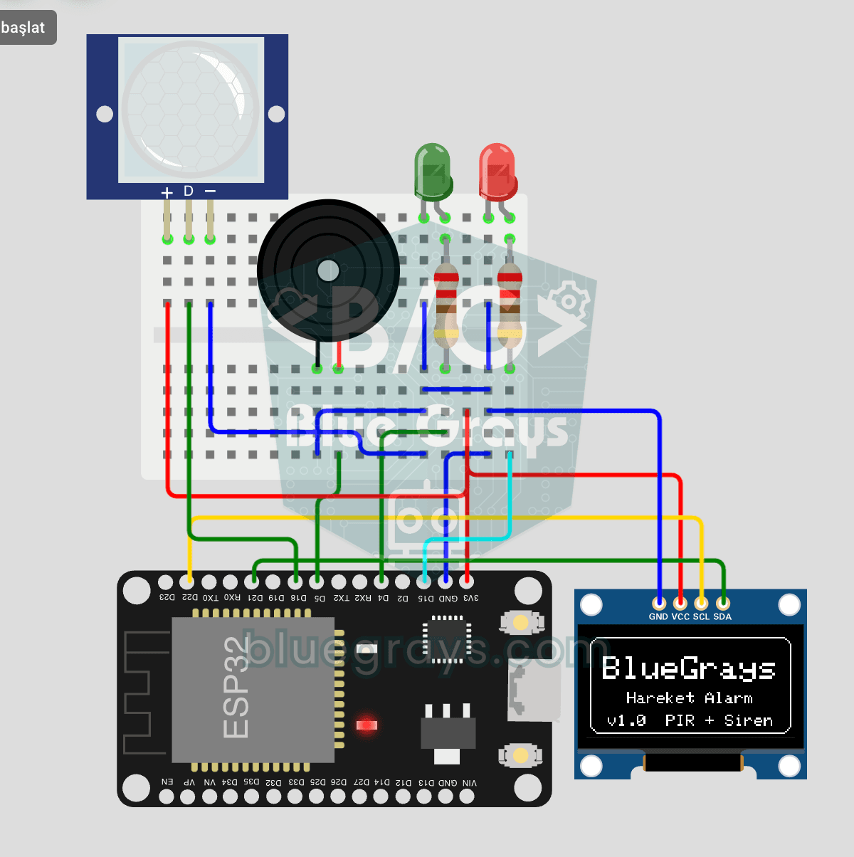
ESP32 Motion Alarm System (PIR + Buzzer + LED + Telegram)
A smart security alarm system that activates the buzzer and LED when the PIR sensor detects motion, while simultaneously sending an instant notification to the owner via Telegram. It includes a 30-second cooldown to limit the frequency of repeated alarms; this mechanism does not validate PIR detections or eliminate false triggers. Suitable for home security, garage monitoring, warehouses, or workrooms. With ESP32-CAM, photo notifications can be added; with the classic ESP32 DevKit V1, text notif