
MAX30102 Arduino: Heart Rate and SpO2 Sensor Wiring and Code
How do you use the MAX30102 with Arduino? I2C wiring (0x57), how red and IR light measure pulse and SpO2, SparkFun library, and code for Uno, ESP32 and Pico.

MAX30102 is a small optical sensor used in Arduino projects to measure pulse (heart rate) and blood oxygen saturation (SpO2) from your fingertip. A single chip contains a red and an infrared (IR) LED, a photodiode that detects light, an 18-bit ADC and a memory (FIFO) that stores the readings. It talks to Arduino over just two data wires, I2C, so you can connect it to an Uno, ESP32 or Raspberry Pi Pico in a few minutes. The pharmacy fingertip oximeters you can buy work on exactly this principle.
In this post you'll see step by step how the MAX30102 measures pulse and oxygen with light, the module pins and a wiring table for each board, how to read pulse on an Arduino Uno with the SparkFun library, how to calculate pulse and SpO2 together on an ESP32, and library-free MicroPython code for the Pico. At the end you'll learn how to beat the two biggest enemies of good readings: wrong finger placement and motion.
What is the MAX30102 and how does it work?
The sensor sends red and infrared light into your fingertip, and the photodiode right next to the LEDs measures the light reflected back from the tissue. Because the LEDs and the detector sit on the same face, this is called reflective measurement. With every heartbeat, a little more blood fills the capillaries in your finger; since blood absorbs light, the light returning to the photodiode drops at that moment. This produces a small wave in the measured signal that rises and falls at the same rate as your heart. This method is called photoplethysmography (PPG). If you measure the time between two beats you get the pulse: if beats arrive 0.8 seconds apart, the pulse is 60 / 0.8 = 75 BPM (beats per minute).
Oxygen measurement relies on the two colours behaving differently in blood. Hemoglobin carrying oxygen absorbs more infrared and less red light, while hemoglobin that has released its oxygen absorbs more red light. For each colour the sensor calculates the ratio of the signal's fluctuation (AC) to its constant level (DC) and divides the two ratios: R = (AC_red / DC_red) / (AC_IR / DC_IR). As R gets smaller, SpO2 rises. Maxim's example algorithm converts R to a percentage with roughly SpO2 = −45.060·R² + 30.354·R + 94.845; R = 0.5 gives about 98.8%, while R = 1 gives about 80%. As you can see, a small measurement error means an SpO2 deviation of several points.
| Feature | Value |
|---|---|
| Manufacturer | Maxim Integrated (now Analog Devices) |
| LEDs | Red 660 nm, infrared (IR) 880 nm |
| ADC | Up to 18-bit resolution, 50–3200 samples/second |
| Memory | 32-sample FIFO |
| Interface | I2C, address 0x57 (8-bit notation: write 0xAE, read 0xAF), up to 400 kHz |
| Chip supply | Core 1.8 V, LEDs 3.1–5 V |
| Module supply | VIN 3.3–5 V (the board has regulators) |
| LED current | Software-adjustable from 0 to 50 mA (in 0.2 mA steps) |
| Shutdown current | About 0.7 µA |
| Extra feature | Built-in temperature sensor that measures die temperature |
MAX30102 vs MAX30100 vs analog pulse sensors
| Feature | MAX30102 | MAX30100 | Pulse Sensor / KY-039 |
|---|---|---|---|
| Measures | Pulse + SpO2 | Pulse + SpO2 | Pulse only |
| Output | I2C (digital) | I2C (digital) | Analog voltage |
| ADC resolution | Up to 18-bit | Up to 16-bit | The microcontroller's ADC |
| FIFO | 32 samples | 16 samples | None |
| Light source | Red + IR | Red + IR | Green LED or IR LED |
| Code complexity | Easy with a library | Easy with a library | Simplest with analogRead |
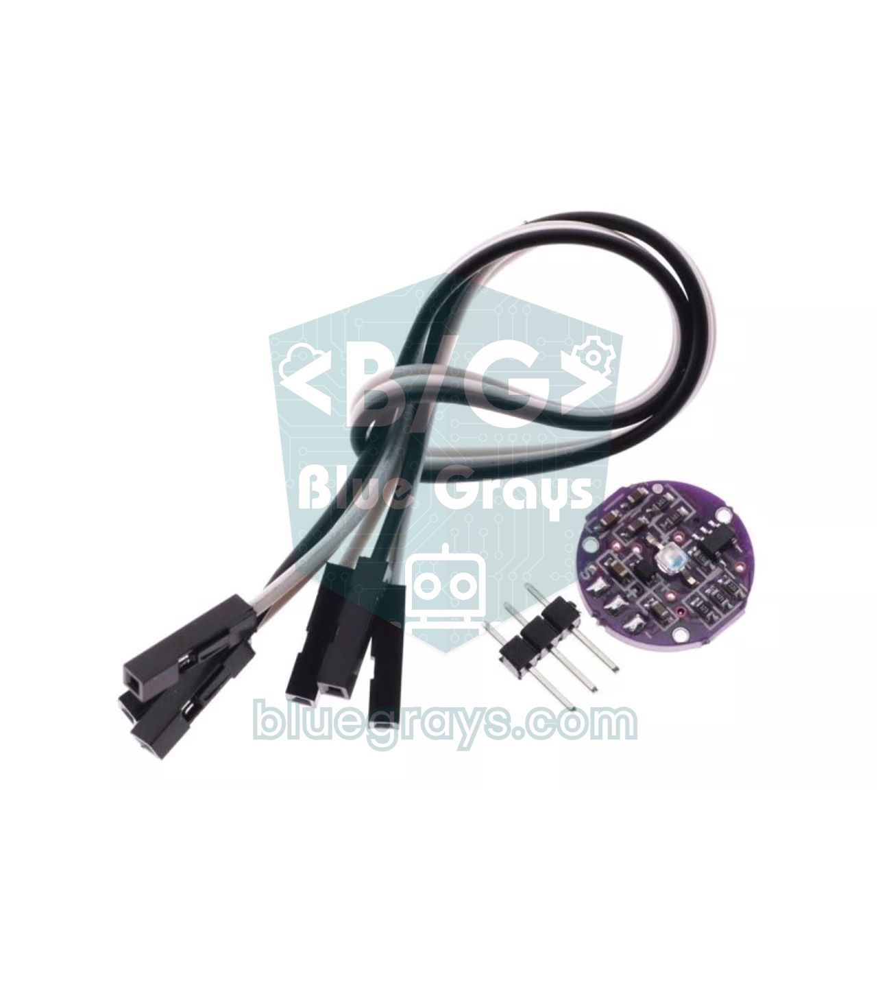
MAX30102 pins and wiring table
| MAX30102 pin | Arduino Uno | ESP32 | Raspberry Pi Pico |
|---|---|---|---|
| VIN | 5V (or 3.3V) | 3V3 | 3V3(OUT) (pin 36) |
| GND | GND | GND | GND |
| SCL | A5 | GPIO 22 | GP5 (pin 7) |
| SDA | A4 | GPIO 21 | GP4 (pin 6) |
| INT | Optional | Optional | Optional |
| IRD / RD | Leave empty | Leave empty | Leave empty |
The sensor's I2C address is fixed: 0x57. If you're unsure about your wiring, you can run an I2C scanner sketch and check that this address is listed; we explained how the I2C bus works in detail in What Is I2C?. The INT pin is an interrupt output pulled LOW when new data is ready; since the code in this post polls the sensor continuously, you don't need this pin. The IRD and RD pins are the LED driver terminals and stay unconnected in normal use.
Installing the library: SparkFun MAX3010x
- Open the Library Manager in the Arduino IDE and type SparkFun MAX3010x.
- Install the SparkFun MAX3010x Pulse and Proximity Sensor Library. Even though MAX30105 appears in its name, it works one-to-one with the MAX30102; the MAX30102 simply has no green LED.
- The library brings three files: MAX30105.h, which drives the sensor, heartRate.h, which detects heartbeats, and spo2_algorithm.h, which contains Maxim's SpO2 algorithm.
- If you're new to installing libraries, take a look at Adding libraries to Arduino.
Measuring pulse (BPM) with Arduino Uno
1#include <Wire.h>
2#include "MAX30105.h"   // MAX30102 ile de çalışır / also works with MAX30102
3#include "heartRate.h"
4
5MAX30105 sensor;
6
7const byte RATE_SIZE = 4;          // son 4 atımın ortalaması / average of last 4 beats
8byte rates[RATE_SIZE];
9byte rateSpot = 0;
10unsigned long lastBeat = 0;
11float bpm = 0;
12int bpmAvg = 0;
13unsigned long lastPrint = 0;
14
15void setup() {
16  Serial.begin(115200);
17  if (!sensor.begin(Wire, I2C_SPEED_FAST)) {        // 400 kHz I2C
18    Serial.println(F("MAX30102 bulunamadi / not found"));
19    while (1);
20  }
21  // parlaklık, ortalama, mod (2 = kırmızı + IR), örnek hızı, darbe genişliği, ADC aralığı
22  // brightness, averaging, mode (2 = red + IR), sample rate, pulse width, ADC range
23  sensor.setup(0x1F, 4, 2, 400, 411, 4096);
24  sensor.setPulseAmplitudeRed(0x0A);   // kırmızı LED kısık, ölçüm IR ile / dim red LED, IR does the work
25}
26
27void loop() {
28  long ir = sensor.getIR();
29
30  if (checkForBeat(ir)) {                      // yeni bir atım yakalandı / a new beat detected
31    unsigned long now = millis();
32    unsigned long delta = now - lastBeat;
33    lastBeat = now;
34    bpm = 60.0 / (delta / 1000.0);
35    if (bpm > 20 && bpm < 255) {               // mantıksız değerleri at / drop impossible values
36      rates[rateSpot++] = (byte)bpm;
37      rateSpot %= RATE_SIZE;
38      bpmAvg = 0;
39      for (byte i = 0; i < RATE_SIZE; i++) bpmAvg += rates[i];
40      bpmAvg /= RATE_SIZE;
41    }
42  }
43
44  if (millis() - lastPrint > 500) {            // yarım saniyede bir yaz / print every 0.5 s
45    lastPrint = millis();
46    Serial.print(F("IR="));
47    Serial.print(ir);
48    if (ir < 50000) {
49      Serial.println(F("  Parmak yok / No finger"));
50    } else {
51      Serial.print(F("  BPM="));
52      Serial.print(bpm, 0);
53      Serial.print(F("  Ort/Avg="));
54      Serial.println(bpmAvg);
55    }
56  }
57}| Code snippet | What it does |
|---|---|
| sensor.begin(Wire, I2C_SPEED_FAST) | Starts the sensor at 400 kHz I2C; returns false if it can't find it. |
| sensor.setup(0x1F, 4, 2, 400, 411, 4096) | Selects about 6.2 mA LED current, 4-sample averaging, red + IR mode, 400 samples/s, 411 µs pulse width and a 4096 nA ADC range. |
| sensor.getIR() | Returns the latest infrared reading; usually above 50,000 when a finger is present. |
| checkForBeat(ir) | Returns true whenever it catches a beat peak in the signal. |
| 60.0 / (delta / 1000.0) | Converts the milliseconds between two beats into beats per minute. |
| rates[] array | Smooths jumping values by averaging the last 4 readings. |
Reading pulse and SpO2 together (ESP32 and Uno)
Measuring oxygen takes more than counting peaks; you need a few seconds of recorded red and IR signals. The code below is set up to take 25 samples per second (100 Hz measurement, 4× averaging) and fills a window of 100 samples, that is, 4 seconds. Maxim's algorithm then calculates both pulse and SpO2 from this window. On each following round the oldest 25 samples are dropped and 25 new ones are added, so you get a new result every second. Because the Uno's 2 KB of RAM is tight for two 32-bit arrays, the code automatically switches to 16-bit arrays on the Uno; SparkFun's official example takes the same approach.
1#include <Wire.h>
2#include "MAX30105.h"
3#include "spo2_algorithm.h"
4
5MAX30105 sensor;
6
7#if defined(__AVR_ATmega328P__) || defined(__AVR_ATmega168__)
8uint16_t irBuffer[100];    // Uno'da RAM yetmediği için 16 bit / 16-bit on Uno to save RAM
9uint16_t redBuffer[100];
10#else
11uint32_t irBuffer[100];    // ESP32'de tam 32 bit / full 32-bit on ESP32
12uint32_t redBuffer[100];
13#endif
14
15const int32_t BUFFER_LENGTH = 100;   // 25 örnek/s x 4 s / 25 samples/s x 4 s
16int32_t spo2;
17int8_t validSpo2;
18int32_t heartRate;
19int8_t validHeartRate;
20bool firstFill = true;
21
22void readSample(int i) {
23  while (!sensor.available()) sensor.check();   // yeni örnek bekle / wait for a new sample
24  redBuffer[i] = sensor.getRed();
25  irBuffer[i] = sensor.getIR();
26  sensor.nextSample();
27}
28
29void setup() {
30  Serial.begin(115200);
31#if defined(ESP32)
32  Wire.begin(21, 22);                           // SDA, SCL
33#endif
34  if (!sensor.begin(Wire, I2C_SPEED_FAST)) {
35    Serial.println(F("MAX30102 bulunamadi / not found"));
36    while (1);
37  }
38  // parlaklık 60 (~12 mA), 4 ortalama, kırmızı + IR, 100 Hz, 411 us, 4096 nA
39  // brightness 60 (~12 mA), average 4, red + IR, 100 Hz, 411 us, 4096 nA
40  sensor.setup(60, 4, 2, 100, 411, 4096);
41}
42
43void loop() {
44  if (firstFill) {                              // ilk 4 saniyeyi doldur / fill the first 4 seconds
45    for (int i = 0; i < BUFFER_LENGTH; i++) readSample(i);
46    firstFill = false;
47  } else {                                      // 25 örnek kaydır, 25 yeni oku / shift 25, read 25 new
48    for (int i = 25; i < BUFFER_LENGTH; i++) {
49      redBuffer[i - 25] = redBuffer[i];
50      irBuffer[i - 25] = irBuffer[i];
51    }
52    for (int i = 75; i < BUFFER_LENGTH; i++) readSample(i);
53  }
54
55  maxim_heart_rate_and_oxygen_saturation(irBuffer, BUFFER_LENGTH, redBuffer,
56                                         &spo2, &validSpo2, &heartRate, &validHeartRate);
57
58  Serial.print(F("Nabiz / HR: "));
59  if (validHeartRate) Serial.print(heartRate); else Serial.print(F("--"));
60  Serial.print(F(" BPM   SpO2: "));
61  if (validSpo2) Serial.print(spo2); else Serial.print(F("--"));
62  Serial.println(F(" %"));
63}| setup() parameter | Value in this code | Options |
|---|---|---|
| ledBrightness | 60 (about 12 mA) | 0 = off … 255 = 50 mA |
| sampleAverage | 4 | 1, 2, 4, 8, 16, 32 |
| ledMode | 2 (red + IR) | 1 = red only, 2 = red + IR, 3 = green too (MAX30105 only) |
| sampleRate | 100 | 50, 100, 200, 400, 800, 1000, 1600, 3200 |
| pulseWidth | 411 µs (18 bit) | 69, 118, 215, 411 µs |
| adcRange | 4096 nA | 2048, 4096, 8192, 16384 |
MAX30102 with the ESP32
The SpO2 code above runs on the ESP32 without any changes; the default I2C pins are GPIO 21 (SDA) and GPIO 22 (SCL), and since the code only uses the Wire library, it compiles the same way on both 2.x and 3.x versions of the ESP32 Arduino core. Always power the module from the 3V3 pin so the I2C lines stay at 3.3 V. The ESP32's plentiful RAM easily accommodates 32-bit buffers, and its second core and Wi-Fi make it easy to send measurements to a phone or the internet. For example, you can show the results on an OLED display, send them to your phone over Bluetooth BLE, or measure at short intervals and go into deep sleep in between to extend battery life. The OLED and the sensor can share the same I2C bus; their addresses differ (0x3C and 0x57), so there's no conflict.
MAX30102 with Raspberry Pi Pico and MicroPython
There's no ready-made, official MAX30102 driver for MicroPython, but because the sensor's registers are simple, you can manage it yourself in a few lines. The code below puts the sensor into SpO2 mode, reads red and IR samples from the FIFO, detects beats from the IR signal, and calculates the R ratio from a 4-second window to print an approximate SpO2 value. If you're new to the Pico and MicroPython, first check out What Is the Raspberry Pi Pico? and MicroPython basics.
1from machine import Pin, I2C
2import time
3
4ADDR = 0x57                       # MAX30102 I2C adresi / I2C address
5i2c = I2C(0, sda=Pin(4), scl=Pin(5), freq=400000)
6
7def wr(reg, val):
8    i2c.writeto_mem(ADDR, reg, bytes([val]))
9
10def rd(reg, n=1):
11    return i2c.readfrom_mem(ADDR, reg, n)
12
13if rd(0xFF)[0] != 0x15:           # PART_ID kontrolü / PART_ID check
14    raise RuntimeError("MAX30102 bulunamadi / not found")
15
16wr(0x09, 0x40)                    # yazılımla sıfırla / software reset
17time.sleep_ms(100)
18wr(0x08, 0x5F)                    # 4 örnek ortalama + FIFO rollover / 4-sample average + rollover
19wr(0x09, 0x03)                    # SpO2 modu: kırmızı + IR / SpO2 mode: red + IR
20wr(0x0A, 0x27)                    # 4096 nA, 100 Hz, 411 us (18 bit)
21wr(0x0C, 0x24)                    # kırmızı LED ~7,2 mA / red LED ~7.2 mA
22wr(0x0D, 0x24)                    # IR LED ~7,2 mA / IR LED ~7.2 mA
23for reg in (0x04, 0x05, 0x06):    # FIFO işaretçilerini sıfırla / reset FIFO pointers
24    wr(reg, 0)
25
26def read_fifo():
27    n = (rd(0x04)[0] - rd(0x06)[0]) & 0x1F   # bekleyen örnek / pending samples
28    out = []
29    if n:
30        d = rd(0x07, 6 * n)                   # her örnek 6 bayt / 6 bytes per sample
31        for i in range(n):
32            k = 6 * i
33            red = ((d[k] << 16) | (d[k + 1] << 8) | d[k + 2]) & 0x3FFFF
34            ir = ((d[k + 3] << 16) | (d[k + 4] << 8) | d[k + 5]) & 0x3FFFF
35            out.append((red, ir))
36    return out
37
38FS = 25                           # 100 Hz / 4 ortalama = 25 örnek/s / effective sample rate
39WIN = 100                         # 4 saniyelik pencere / 4 second window
40reds, irs, beats = [], [], []
41dc = 0.0
42above = False
43count = 0
44last_beat = 0
45
46while True:
47    for red, ir in read_fifo():
48        count += 1
49        if ir < 50000:                        # parmak yok / no finger
50            reds, irs, beats = [], [], []
51            dc = 0.0
52            last_beat = 0
53            if count % FS == 0:
54                print("Parmak yok / No finger")
55            continue
56        if dc == 0.0:
57            dc = ir
58        dc += 0.05 * (ir - dc)                # yavaş ortalama = DC / slow average = DC
59        ac = dc - ir                          # kan dolunca ışık azalır / light drops as blood fills
60        reds.append(red)
61        irs.append(ir)
62        if len(irs) > WIN:
63            reds.pop(0)
64            irs.pop(0)
65        thr = (max(irs) - min(irs)) * 0.2     # uyarlanır eşik / adaptive threshold
66        if not above and ac > thr and count - last_beat > FS * 0.3:
67            above = True
68            if last_beat:
69                bpm = 60 * FS / (count - last_beat)
70                if 40 <= bpm <= 200:
71                    beats.append(bpm)
72                    if len(beats) > 4:
73                        beats.pop(0)
74            last_beat = count
75        elif ac < 0:
76            above = False
77        if count % FS == 0 and len(irs) == WIN and beats:
78            ac_r = max(reds) - min(reds)
79            ac_i = max(irs) - min(irs)
80            if ac_i > 0:
81                R = (ac_r / (sum(reds) / WIN)) / (ac_i / (sum(irs) / WIN))
82                spo2 = min(100, -45.060 * R * R + 30.354 * R + 94.845)
83                print("BPM: %d  SpO2: %d %%" % (int(sum(beats) / len(beats)), int(spo2)))
84    time.sleep_ms(20)
The code first checks that the PART_ID register is 0x15; this value shows the sensor really is a MAX30102. The 0x27 written to register 0x0A packs the 4096 nA ADC range, the 100 Hz sample rate and the 411 µs pulse width into a single byte. In SpO2 mode each sample in the FIFO is 6 bytes: the first 3 bytes are the red reading, the next 3 the IR reading, and each is an 18-bit number. For beat detection, the slow average (DC) of the IR signal is subtracted to leave only the pulse wave (AC); a beat is counted when the wave exceeds 20% of the window amplitude, and at least 300 ms must pass between two beats, which allows a maximum of 200 BPM. Because SpO2 is calculated here with a simple peak-to-peak method, it's only an approximate value for educational purposes.
Correct finger placement and motion error
- Use your fingertip: Place the soft pad of your index or middle finger on the LEDs, directly opposite the nail.
- Press lightly: Pressing too hard pushes blood out of the capillaries and shrinks the wave; holding too loosely lets ambient light leak in. A steady, light pressure from a rubber band or a Velcro strap gives ideal results.
- Block ambient light: Sunlight and fluorescent lamps leak into the sensor and corrupt the signal; covering the finger and sensor with a dark sleeve noticeably improves the measurement.
- Warm your finger: Blood flow decreases in a cold finger and the signal weakens. Even rubbing your hands together for a few seconds before measuring makes a difference.
- Keep the wires and board steady: A module wobbling on a breadboard adds noise to the signal with every touch; fix the sensor to the desk or a case.
- Talking and moving: Moving your finger, talking or raising and lowering your arm during measurement creates fluctuations far larger than the pulse wave.
Motion error is the biggest problem in MAX30102 projects. The pulse wave is only about 1–2% of the total light the sensor measures; a finger slipping by a few millimetres causes a much bigger change, and the algorithm mistakes that fluctuation for a beat. As a result you suddenly see unrealistic values like 150 or 40 BPM in the Serial Monitor. To reduce this, measure while holding still, average several results and discard invalid (valid = 0) results instead of displaying them. More advanced projects use moving-average, median or band-pass filters; you can find their Arduino equivalents in the sensor data filtering post.
MAX30102 project ideas
- Desktop heart rate display: show BPM and SpO2 in big digits with a scrolling pulse wave on an SSD1306 OLED display.
- Beat sound: play a short "beep" on a buzzer with every beat for a pharmacy-oximeter feel.
- Post-workout recovery test: measure your pulse right after exercise and 1 minute later, then calculate the difference.
- Data logger: write the readings with timestamps to an SD card, then plot them on your computer.
- ESP32 notification system: when a measurement is complete, send the result to your phone as a message via a Telegram bot.
- Science fair comparison: run an analog pulse sensor and the MAX30102 at the same time and tabulate which gives more stable results.
Common mistakes and how to fix them
| Symptom | Likely cause | Fix |
|---|---|---|
| "MAX30102 not found" | SDA and SCL swapped, VIN not connected, or pull-ups at 1.8 V | Check the wires, look for 0x57 with an I2C scanner, move the solder bridge to 3.3 V |
| IR value always below 50,000 | Finger isn't directly on the sensor or LED current is too low | Centre your finger over the LEDs, increase ledBrightness |
| Values near 262,143 and never changing | ADC has saturated, light is too strong | Lower ledBrightness or set adcRange to 8192 or 16384 |
| BPM jumps between 40 and 180 | Motion, pressing too hard or ambient light | Steady your finger, press lightly, shield the sensor from light |
| SpO2 constantly "--" or -999 | Algorithm finds the signal invalid (validSpo2 = 0) | Stay still for 4 seconds, warm your finger and secure it with a strap |
| Code freezes or acts strangely on the Uno | Not enough RAM, other large libraries are also loaded | Keep the 16-bit buffers, put strings in F() or switch to an ESP32 |
The MAX30102 is a wonderful learning sensor that shows how elegant it can be to read the body with two colours of light and a clever algorithm; just interpret the readings as experiment data, not as medical results. If you want to reinforce reading sensors over I2C, showing values on a screen and logging data, in the BlueGrays app you can explore measurement projects like DHT11, LDR, I2C LCD, OLED weather display and temperature logger, step by step with circuit diagrams and ready-made code.
Frequently asked questions
How accurate is the SpO2 value measured with the MAX30102?
Because hobby modules are uncalibrated, the SpO2 value can deviate by several points from an approved oximeter, and motion and ambient light widen that gap even more. The results are for experimenting and learning and shouldn't be used for health decisions.
Does the MAX30102 work at 5 V?
Since common MAX30102 modules have a regulator on board, the VIN pin can be powered with 3.3 V or 5 V. However, on some boards the I2C pull-up resistors are tied to 1.8 V and a 5 V Uno may not see the sensor; in that case you need to move the solder bridge on the board to the 3.3 V side.
What is the difference between the MAX30100 and MAX30102?
Both measure pulse and SpO2 with red and IR LEDs. The MAX30102 is the newer chip; it offers up to 18-bit ADC resolution, a 32-sample FIFO and lower power consumption. The MAX30100's ADC goes up to 16 bits and its FIFO holds 16 samples.
Why does my MAX30102 give a "sensor not found" error?
The most common causes are SDA and SCL wires swapped, a missing VIN or GND connection, and pull-up resistors tied to 1.8 V. Run an I2C scanner sketch and see whether address 0x57 appears; if it doesn't, the problem is the wiring, not the code.
What are normal pulse and SpO2 values?
In resting adults, pulse is usually between 60 and 100 beats per minute and can be lower in athletes. In healthy people SpO2 is usually between 95% and 100%. If your hobby sensor shows a value outside this range, check your measurement conditions first, and if you have a real concern, consult an approved device.
Can the MAX30102 measure from the wrist or ear?
Because the sensor works by reflection, it can pick up a pulse wave at the wrist or earlobe too, but the signal in these places is much weaker than at the fingertip and very sensitive to motion. Smartwatches therefore use stronger LEDs, accelerometer-assisted motion correction and more advanced algorithms.
Projects to build after reading this
See all projects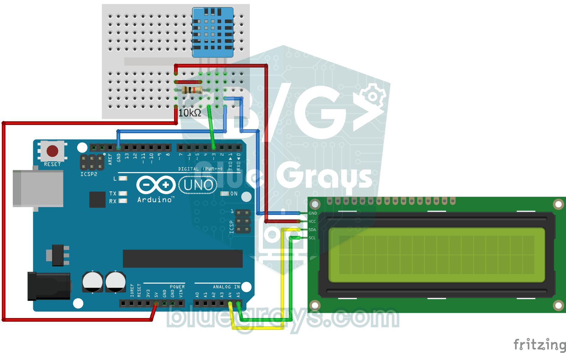
Temperature and Humidity with DHT11
How warm is your room, and is the air humid or dry? The DHT11 sensor measures temperature and humidity, and the Arduino writes the values on a two-line LCD screen, refreshing every couple of seconds.
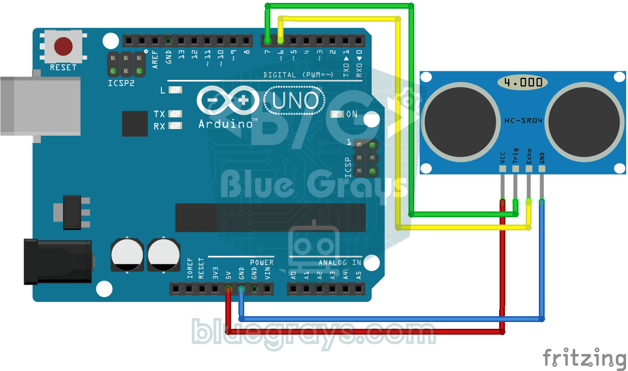
HC-SR04 Distance Measurement (Serial Display)
The HC-SR04 sensor works just like a bat finding its way in the dark: it sends out a sound you cannot hear, listens for the echo and measures how far away the object in front of it is.

Measuring Light Intensity with an LDR
Want to see how bright your room is as a number? The LDR, a small part that reacts to light, measures the light around it, and the Arduino writes the value to your computer screen every half second.
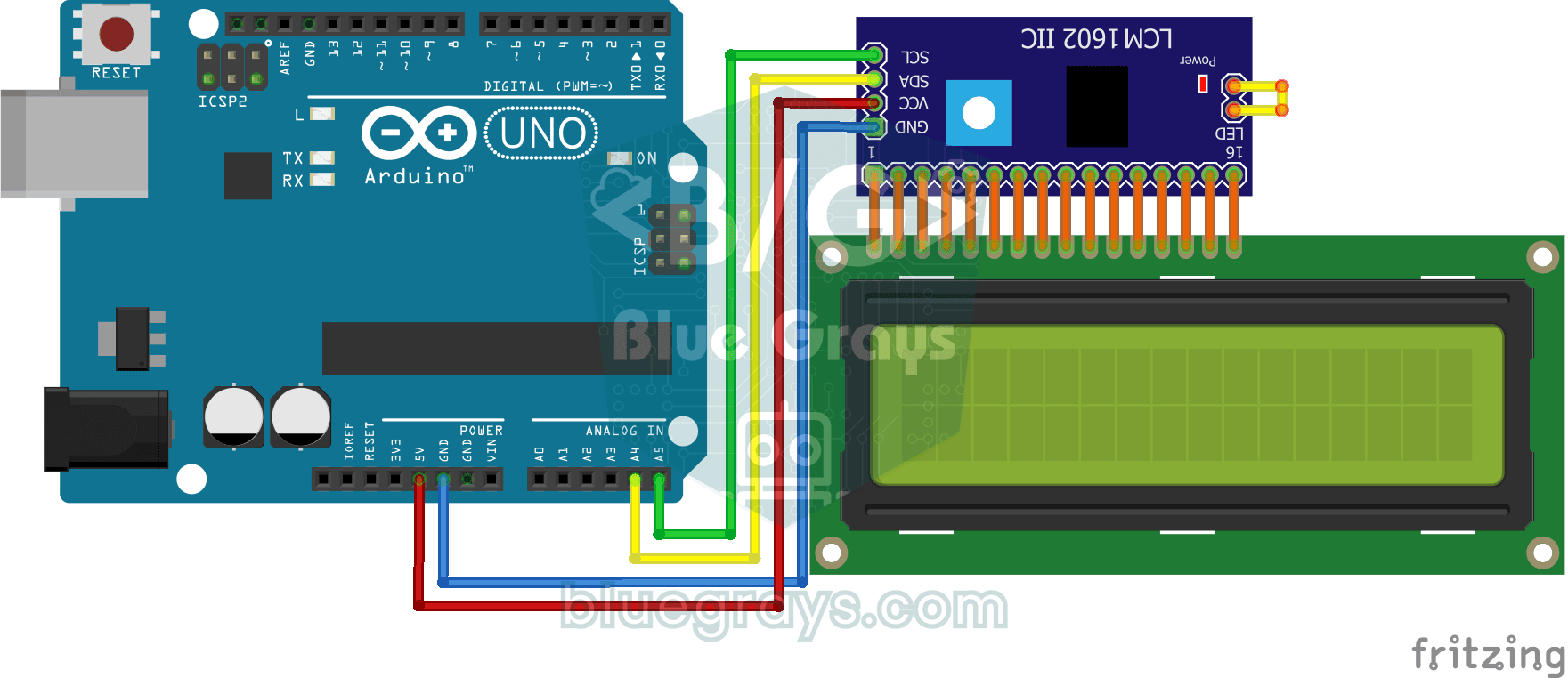
Using LCD Screen with I2C
Give your Arduino its own screen and make it write its first message. The two-line LCD screen hooks up with just a few wires; a greeting appears on the top line, then a second message on the bottom…

ESP32 I2C LCD Display (16x2)
In this project we connect a 16x2 character LCD to the ESP32 over I2C and display text. With I2C, just 2 data pins (SDA and SCL) control the screen, instead of the 6+ pins a classic parallel connection wastes. The code prints a fixed message on the first line and a counter that goes up every second on the second. At startup an I2C scanner also prints the display's address to the Serial Monitor (usually 0x27 or 0x3F).

ESP32 HTTPClient + Weather API (with SSD1306 OLED Display)
In this project the ESP32 makes a REST API call over the internet to a weather API (wttr.in) using HTTPClient.h. Unlike the I2C LCD version, it uses an SSD1306 OLED (128×64) display, with large text and vector icons for a richer look. Seven weather icons (sunny, rainy, snowy and more) are drawn on the fly, with no bitmap files.

ESP32 Deep Sleep — Battery Saving (OLED + RTC RAM Counter)
The ESP32's Deep Sleep mode shuts down the CPU and most peripherals, cutting current draw to about 10µA, which is vital for battery-powered IoT devices. This project uses three wake-up sources: a timer (15 s), an external pin (EXT0, the button on GPIO 33) and a touch pin (T0/GPIO 4). Counters marked with RTC_DATA_ATTR survive deep sleep.
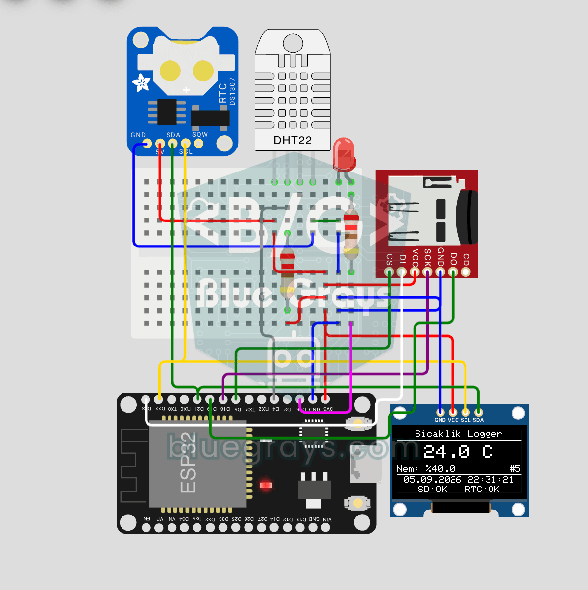
ESP32 Temperature Data Logger (DHT22 + DS1307 RTC + microSD + OLED)
Build a timed temperature and humidity logger with the ESP32! A DHT22 sensor reads temperature and humidity once a minute, and each reading is saved to a microSD card in CSV format with a real-time stamp from the DS1307 RTC module. The OLED display shows the latest temperature, humidity, timestamp and total number of records live, in large text.