
Motor Driver Comparison: L298N, L293D, TB6612FNG, A4988
L298N, L293D, L9110S, TB6612FNG and A4988 compared: current, voltage drop, efficiency and 3.3 V compatibility, with picks for robot cars and stepper motors.

The first questions to ask when comparing motor drivers are: how much current does your motor draw, what voltage does it run on, and what logic level (5 V or 3.3 V) does your board use? The five drivers hobbyists use most are the L298N, L293D, L9110S, TB6612FNG and A4988. The short answer: the TB6612FNG is best for a small battery-powered robot car, the L298N for 12 V motors drawing 1–2 A, the L9110S for the tightest budget, an L293D shield for driving four motors from one board on an Arduino Uno, and the A4988 for bipolar stepper motors such as the NEMA 17.
In this guide we look at how much current each driver can really deliver, how much voltage it loses, what that loss does to battery life and heat, and how well it works with 3.3 V boards such as the ESP32 and Raspberry Pi Pico. You'll also find working code that drives the same two motors with Arduino, ESP32 and Pico, a stepper example with the A4988, and a project-by-project selection table.
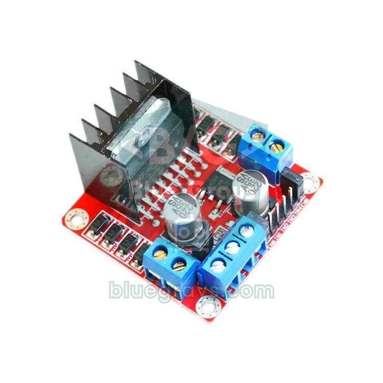
What is a motor driver and why do you need one?
An Arduino digital pin can supply only about 20–40 mA at most. Even a small TT gear motor draws 150–250 mA when running and close to 1 A when stalled. Connecting a motor straight to a pin burns the pin out, and the reverse-voltage spikes the motor generates can reset the microcontroller. A motor driver is a switching circuit that takes the weak signal from the microcontroller and powers the motor from a separate supply. At the heart of DC motor drivers is the H-bridge: switching four switches on and off in diagonal pairs reverses the polarity across the motor, so it turns forward or backward. Speed is set with a PWM signal that switches them on and off thousands of times per second. Stepper drivers go one step further: they energise the coils in sequence while limiting the current, turning the motor in precise angles.
The five drivers at a glance
- L298N: An old but very common dual bipolar-transistor H-bridge. It tolerates high voltage (5–35 V on the module) and can reach 2 A per channel, but it loses 2–3 V and runs very hot. For details, see DC motor control with the L298N.
- L293D: A 16-pin DIP chip with 600 mA continuous and 1.2 A peak current per channel, plus built-in protection diodes. It's famous for the L293D motor shield, which was made for the Arduino Uno and drives four DC motors.
- L9110S: The cheapest and smallest option. It works from 2.5–12 V and gives about 800 mA per channel; there's no enable pin, so each motor is controlled with two pins. More in the L9110S motor driver article.
- TB6612FNG: A modern MOSFET-based H-bridge. It gives 1.2 A continuous and 3.2 A peak per channel with an on-resistance of about 0.5 ohm, so it barely warms up and works fine with logic levels from 2.7 V.
- A4988: Not a DC motor driver but a bipolar stepper driver. It offers 8–35 V motor voltage, an adjustable current limit and microstepping up to 1/16. Setup is explained step by step in the A4988 stepper motor driver article.
Comparison table: current, voltage, 3.3 V compatibility and price
| Feature | L298N | L293D | L9110S | TB6612FNG | A4988 |
|---|---|---|---|---|---|
| Motor type | 2 DC or 1 bipolar stepper | 2 DC or 1 bipolar stepper | 2 DC | 2 DC or 1 bipolar stepper | 1 bipolar stepper |
| Motor voltage | 5–35 V (module) | 4.5–36 V | 2.5–12 V | 4.5–13.5 V (absolute max 15 V) | 8–35 V |
| Continuous current (per channel) | 2 A (with heatsink) | 0.6 A | about 0.8 A | 1.2 A | about 1 A without heatsink, 2 A with cooling |
| Peak current | 3 A | 1.2 A | about 1.5 A | 3.2 A | 2 A |
| Switching technology | Bipolar transistor | Bipolar transistor | Transistor (low saturation) | MOSFET | MOSFET + current control |
| Voltage drop | about 2–3 V | about 1.8–2.6 V | about 1 V | about 0.5 V (at 1 A) | Current-controlled, not an issue |
| Efficiency | Low | Low | Medium | High | High |
| Logic supply | 5 V (regulator on module) | 4.5–7 V (VCC1) | Shared with motor supply | 2.7–5.5 V (VCC) | 3–5.5 V (VDD) |
| 3.3 V signal compatibility | Usually works | Inputs accept it, logic supply is 5 V | Fully compatible | Fully compatible | Fully compatible |
| Price (relative) | Low | Low | Very low | Medium | Low |
The current values in the table are datasheet limits; in practice the safe zone is about 70% of them. For example, the L298N's 2 A is only possible with a large heatsink and good airflow; push a module without a heatsink above 1 A continuously and the chip heats up quickly and goes into thermal protection. To find a motor's real requirement, look not at the running current but at the stall current: when a wheel hits an obstacle the motor draws this current, and the driver must be able to withstand it, at least briefly. The price column is only a relative ranking: the L9110S is usually the cheapest module, while the TB6612FNG costs a bit more but more than makes up for it with its efficiency and small size.
Voltage drop and efficiency: why does the L298N get so hot?
In bipolar-transistor drivers (L298N, L293D), current passes through two transistors before it reaches the motor, and about 1–1.5 V is lost in each. That loss turns into heat: the lost power is calculated as P = V_drop × I. In the MOSFET-based TB6612FNG the switches behave like a resistor and the loss is P = I² × R_on; for 0.5 ohm and 1 A that's only 0.5 W. In low-voltage battery systems the difference is huge: losing 2 V from a 6 V battery pack means throwing away a third of the motor's power. You can repeat the calculations for your own motor with the Ohm's law calculator and estimate battery life with the battery life calculator. The table below shows typical values for a 6 V supply and 0.6 A motor current:
| Driver | Typical voltage loss | Voltage left for the motor | Power wasted as heat in the driver | Approx. efficiency |
|---|---|---|---|---|
| L298N | 1.8 V | 4.2 V | 1.08 W | 70% |
| L293D | 2.0 V | 4.0 V | 1.2 W | 67% |
| L9110S | 0.8 V | 5.2 V | 0.48 W | 87% |
| TB6612FNG | 0.3 V | 5.7 V | 0.18 W | 95% |
3.3 V compatibility: which driver for the ESP32 and Raspberry Pi Pico?
The pins of the ESP32 and Pico output 3.3 V. Because the TB6612FNG's logic supply (VCC) can be connected directly to 3.3 V, it's the cleanest match for these boards. The A4988's logic inputs also work from 3–5.5 V, and the L9110S's inputs read a 3.3 V signal without trouble. On the L298N and L293D the high-level input threshold is at least 2.3 V, so a 3.3 V signal works in most cases, but the chip's logic section needs a 5 V supply, and running close to the threshold can cause false triggering in a noisy environment. In short: if you're starting a new ESP32 or Pico project, start with the TB6612FNG; if you already have an L298N it will often work too, but never forget the common ground connection.
Wiring: L298N and TB6612FNG pin table
| Function | L298N pin | TB6612FNG pin | Arduino Uno | ESP32 | Raspberry Pi Pico |
|---|---|---|---|---|---|
| Motor A speed (PWM) | ENA | PWMA | D5 | GPIO 25 | GP16 |
| Motor A direction 1 | IN1 | AIN1 | D4 | GPIO 26 | GP17 |
| Motor A direction 2 | IN2 | AIN2 | D7 | GPIO 27 | GP18 |
| Motor B speed (PWM) | ENB | PWMB | D6 | GPIO 13 | GP21 |
| Motor B direction 1 | IN3 | BIN1 | D8 | GPIO 33 | GP19 |
| Motor B direction 2 | IN4 | BIN2 | D9 | GPIO 32 | GP20 |
| Standby / enable | None | STBY | D10 | GPIO 4 | GP22 |
| Logic supply | +5V (regulator output) | VCC | 5V | 3V3 | 3V3 (OUT) |
| Motor supply | +12V | VM | External supply | External supply | External supply |
| Ground | GND | GND | GND | GND | GND |
Step by step: driving two DC motors with Arduino
- Connect the motor supply (for example 7.4 V from two 18650 cells or 9 V from 6×AA) to the driver's motor supply input: +12V on the L298N, VM on the TB6612FNG.
- Connect the negative terminal of the supply to both the driver's GND and the Arduino's GND.
- If you're using an L298N, remove the jumpers on ENA and ENB; otherwise you can't control speed and the motor always runs at full speed.
- Connect the PWM pins to D5 and D6 and the direction pins to D4, D7, D8 and D9, as in the table. On the TB6612FNG, connect STBY to D10 and VCC to the Arduino's 5V.
- Plug the motor leads into the OUT1–OUT2 (A01–A02) and OUT3–OUT4 (B01–B02) outputs. If a motor spins the wrong way, swap its wires or reverse the direction in code.
- Upload the code below and run the first test with the wheels off the ground.
1// L298N ya da TB6612FNG ile iki DC motor / Two DC motors with L298N or TB6612FNG
2const int ENA  = 5;   // PWMA (PWM pini / PWM pin)
3const int IN1  = 4;   // AIN1
4const int IN2  = 7;   // AIN2
5const int ENB  = 6;   // PWMB (PWM pini / PWM pin)
6const int IN3  = 8;   // BIN1
7const int IN4  = 9;   // BIN2
8const int STBY = 10;  // yalnız TB6612FNG / TB6612FNG only
9
10// hiz: -255 (tam geri) ... 255 (tam ileri) / speed: -255 (full reverse) ... 255 (full forward)
11void motorSur(int en, int inA, int inB, int hiz) {
12  hiz = constrain(hiz, -255, 255);
13  if (hiz > 0) {
14    digitalWrite(inA, HIGH);
15    digitalWrite(inB, LOW);
16  } else if (hiz < 0) {
17    digitalWrite(inA, LOW);
18    digitalWrite(inB, HIGH);
19  } else {
20    digitalWrite(inA, LOW);   // dur / stop
21    digitalWrite(inB, LOW);
22  }
23  analogWrite(en, abs(hiz));
24}
25
26// Kısa devre freni: iki giriş HIGH / Short brake: both inputs HIGH
27void fren(int en, int inA, int inB) {
28  digitalWrite(inA, HIGH);
29  digitalWrite(inB, HIGH);
30  analogWrite(en, 255);
31}
32
33void setup() {
34  pinMode(ENA, OUTPUT);
35  pinMode(IN1, OUTPUT);
36  pinMode(IN2, OUTPUT);
37  pinMode(ENB, OUTPUT);
38  pinMode(IN3, OUTPUT);
39  pinMode(IN4, OUTPUT);
40  pinMode(STBY, OUTPUT);
41  digitalWrite(STBY, HIGH);   // TB6612FNG'yi uyandır / wake up the TB6612FNG
42}
43
44void loop() {
45  motorSur(ENA, IN1, IN2, 180);    // ileri / forward
46  motorSur(ENB, IN3, IN4, 180);
47  delay(2000);
48
49  fren(ENA, IN1, IN2);             // fren / brake
50  fren(ENB, IN3, IN4);
51  delay(500);
52
53  motorSur(ENA, IN1, IN2, -180);   // geri / reverse
54  motorSur(ENB, IN3, IN4, -180);
55  delay(2000);
56
57  motorSur(ENA, IN1, IN2, 180);    // yerinde dönüş / spin in place
58  motorSur(ENB, IN3, IN4, -180);
59  delay(1000);
60
61  motorSur(ENA, IN1, IN2, 0);      // dur / stop
62  motorSur(ENB, IN3, IN4, 0);
63  delay(1000);
64}
The nice thing about this code is that it works with the same pin layout on both the L298N and the TB6612FNG; the two drivers' logic tables are almost identical. When one direction pin is HIGH and the other LOW, the motor turns; the PWM value (0–255) sets the speed. When both direction pins are set HIGH, the motor terminals are shorted and the motor brakes with its own generated voltage, which lets the robot stop in a shorter distance on a slope or at speed. The Uno's D5 and D6 pins produce about 980 Hz PWM; a faint whine from the motors at this frequency is normal. With the L298N you'll find the motor doesn't turn at very low PWM values (below about 60), because after the driver's loss the average voltage left for the motor isn't enough to overcome friction.
ESP32 with TB6612FNG: silent 20 kHz PWM
On the ESP32, using the LEDC hardware PWM unit instead of analogWrite lets you choose the frequency yourself. Because the TB6612FNG accepts PWM up to 100 kHz, raising the frequency to 20 kHz moves it into a range the human ear can't hear and the motor whine disappears completely. The code below compiles on both ESP32 Arduino core 2.x and 3.x; the LEDC functions that differ between versions are separated with a conditional compilation block. Don't forget to connect the TB6612FNG's VCC pin to the ESP32's 3V3 pin.
1#include <Arduino.h>
2
3// ESP32 + TB6612FNG pinleri / ESP32 + TB6612FNG pins
4const int PWMA = 25, AIN1 = 26, AIN2 = 27;
5const int PWMB = 13, BIN1 = 33, BIN2 = 32;
6const int STBY = 4;
7
8const int PWM_FREQ = 20000;   // 20 kHz: duyulmayan PWM / inaudible PWM
9const int PWM_RES  = 8;       // 0-255 çözünürlük / 0-255 resolution
10
11void pwmBaslat(int pin, int kanal) {
12#if ESP_ARDUINO_VERSION_MAJOR >= 3
13  ledcAttach(pin, PWM_FREQ, PWM_RES);   // core 3.x
14  (void)kanal;
15#else
16  ledcSetup(kanal, PWM_FREQ, PWM_RES);  // core 2.x
17  ledcAttachPin(pin, kanal);
18#endif
19}
20
21void pwmYaz(int pin, int kanal, int deger) {
22#if ESP_ARDUINO_VERSION_MAJOR >= 3
23  ledcWrite(pin, deger);
24  (void)kanal;
25#else
26  ledcWrite(kanal, deger);
27  (void)pin;
28#endif
29}
30
31// hiz: -255 ... 255 / speed: -255 ... 255
32void motor(int pwmPin, int kanal, int in1, int in2, int hiz) {
33  hiz = constrain(hiz, -255, 255);
34  digitalWrite(in1, hiz > 0 ? HIGH : LOW);
35  digitalWrite(in2, hiz < 0 ? HIGH : LOW);
36  pwmYaz(pwmPin, kanal, abs(hiz));
37}
38
39void setup() {
40  pinMode(AIN1, OUTPUT);
41  pinMode(AIN2, OUTPUT);
42  pinMode(BIN1, OUTPUT);
43  pinMode(BIN2, OUTPUT);
44  pinMode(STBY, OUTPUT);
45  digitalWrite(STBY, HIGH);   // sürücüyü etkinleştir / enable the driver
46  pwmBaslat(PWMA, 0);
47  pwmBaslat(PWMB, 1);
48}
49
50void loop() {
51  for (int h = 0; h <= 255; h += 5) {   // yumuşak hızlanma / soft acceleration
52    motor(PWMA, 0, AIN1, AIN2, h);
53    motor(PWMB, 1, BIN1, BIN2, h);
54    delay(30);
55  }
56  delay(1500);
57  motor(PWMA, 0, AIN1, AIN2, -200);     // geri / reverse
58  motor(PWMB, 1, BIN1, BIN2, -200);
59  delay(1500);
60  motor(PWMA, 0, AIN1, AIN2, 0);        // dur / stop
61  motor(PWMB, 1, BIN1, BIN2, 0);
62  delay(1000);
63}
Raspberry Pi Pico and MicroPython with TB6612FNG
All of the Pico's GPIO pins can produce hardware PWM, and in MicroPython the duty cycle is given as a 16-bit number (0–65535). In the example below, speed is entered as a percentage (from -100 to 100) and the function converts it to a duty_u16 value. Because GP16 and GP21 are on different PWM slices, the two motors' frequencies don't affect each other. Connect the TB6612FNG's VCC pin to the Pico's 3V3 (OUT) pin and the VM pin to the external motor supply; powering motors from the Pico's VSYS pin causes the board to reset because of the limited current coming from USB.
1from machine import Pin, PWM
2import time
3
4stby = Pin(22, Pin.OUT, value=1)   # sürücüyü uyandır / wake the driver
5
6pwma = PWM(Pin(16))
7pwma.freq(20000)                   # 20 kHz sessiz PWM / quiet PWM
8ain1 = Pin(17, Pin.OUT)
9ain2 = Pin(18, Pin.OUT)
10
11pwmb = PWM(Pin(21))
12pwmb.freq(20000)
13bin1 = Pin(19, Pin.OUT)
14bin2 = Pin(20, Pin.OUT)
15
16def motor(pwm, in1, in2, hiz):     # hiz: -100 ... 100 / speed in percent
17    hiz = max(-100, min(100, hiz))
18    in1.value(1 if hiz > 0 else 0)
19    in2.value(1 if hiz < 0 else 0)
20    pwm.duty_u16(int(abs(hiz) * 65535 / 100))
21
22while True:
23    motor(pwma, ain1, ain2, 70)    # ileri / forward
24    motor(pwmb, bin1, bin2, 70)
25    time.sleep(2)
26    motor(pwma, ain1, ain2, -70)   # geri / reverse
27    motor(pwmb, bin1, bin2, -70)
28    time.sleep(2)
29    motor(pwma, ain1, ain2, 0)     # dur / stop
30    motor(pwmb, bin1, bin2, 0)
31    time.sleep(1)
Stepper motors with the A4988: current limit and Vref setting
The L298N and L293D can also drive a bipolar stepper with two H-bridges, but because they can't limit current, the motor either lacks power at low voltage or overheats at high voltage. The A4988 continuously measures the coil current and keeps it constant (chopper drive), so even a 2.8 V NEMA 17 motor can be driven safely with high torque from a 12 V or 24 V supply. The current limit is set with the small trimpot on the board and the formula is: I_max = Vref / (8 × Rs). Rs is the current-sense resistor on the board; many clone boards say R100 (0.1 ohm) and some say R068 (0.068 ohm). For example, on a 0.1 ohm board, for 1 A you need Vref = 1 × 8 × 0.1 = 0.8 V; to leave a heat margin, about 0.56 V (70%) is a good starting point. The A4988 is controlled with just two pins: each pulse on the STEP pin is one step and the DIR pin sets the direction. With MS1, MS2 and MS3 LOW it runs in full steps, and a 1.8-degree motor takes 200 steps per revolution. Remember to connect SLEEP and RESET together and to place a capacitor of at least 100 µF between VMOT and GND.
1// A4988 ile NEMA 17 step motor / NEMA 17 stepper with A4988
2// MS1-MS3 LOW = tam adım, SLEEP ile RESET birbirine bağlı / MS1-MS3 LOW = full step, SLEEP tied to RESET
3const int DIR_PIN  = 2;
4const int STEP_PIN = 3;
5const int ADIM_TUR = 200;   // 1,8 derece motor / 1.8 degree motor
6
7void adimAt(int adim, bool yon, unsigned int bekleme) {
8  digitalWrite(DIR_PIN, yon ? HIGH : LOW);
9  for (int i = 0; i < adim; i++) {
10    digitalWrite(STEP_PIN, HIGH);
11    delayMicroseconds(bekleme);
12    digitalWrite(STEP_PIN, LOW);
13    delayMicroseconds(bekleme);
14  }
15}
16
17void setup() {
18  pinMode(DIR_PIN, OUTPUT);
19  pinMode(STEP_PIN, OUTPUT);
20}
21
22void loop() {
23  adimAt(ADIM_TUR, true, 800);    // saat yönünde 1 tur / one turn clockwise
24  delay(1000);
25  adimAt(ADIM_TUR, false, 800);   // ters yönde 1 tur / one turn counter-clockwise
26  delay(1000);
27}Which driver for which project?
| Project | Recommended driver | Why? |
|---|---|---|
| Robot car with 2 TT motors (battery-powered) | TB6612FNG (L9110S on a budget) | Low loss, long battery life, small size |
| 4-wheel car with an Arduino Uno | L293D shield or L298N | 4 motors on one board; with the L298N, the 2 motors on each side are wired in parallel |
| 12 V gear motor (1–2 A) | L298N (with heatsink) | Handles high voltage and current; for bigger motors move to MOSFET drivers such as the BTS7960 |
| NEMA 17 stepper (3D printer, CNC, slider) | A4988 | Current limit and microstepping |
| 28BYJ-48 stepper | ULN2003 board | Unipolar motor, directly compatible with 5 V |
| One-direction 6 V mini water pump | Logic-level MOSFET or a single L9110S channel | An H-bridge is unnecessary if the direction never changes |
| Reversible pump or peristaltic pump | TB6612FNG | Direction change and efficient PWM |
| Any DC motor project based on ESP32 or Pico | TB6612FNG | Full match with 3.3 V logic |
The pump example is especially important: in an irrigation system the pump always turns the same way, so a single N-channel MOSFET and a flyback diode are enough; you can find this method in the Using a MOSFET with Arduino article. In robot cars, the lower the battery voltage, the greater the advantage of a MOSFET driver; a car powered by two 18650 batteries will visibly go faster and run longer with a TB6612FNG than with an L298N.
Project ideas with motor drivers
- Bluetooth-controlled robot car: Drive two motors from your phone with a TB6612FNG or L298N; the steps are in the building a robot car article.
- Obstacle-avoiding robot: A vehicle that detects an obstacle ahead with an HC-SR04 and changes direction; details in the obstacle-avoiding robot article.
- Line-following robot: In this project, which needs fast PWM response, the TB6612FNG's efficiency makes a difference; take a look at the line-following robot article.
- Automatic irrigation: Run the mini pump when soil moisture drops; the power connections are explained in the mini water pump article.
- Solar tracking system: Turn a panel toward the light with a stepper or a geared DC motor; see the solar tracking system article.
- Precise positioning: For a camera slider or turntable that rotates in small angles, start with a 28BYJ-48 stepper motor and move up to the A4988 and NEMA 17.
Common mistakes and how to fix them
| Problem | Likely cause | Fix |
|---|---|---|
| Arduino resets when the motor runs | The motor is powered from the Arduino's 5V or the supply is weak | Use a separate motor supply, join the GNDs, add a 100–470 µF capacitor across the supply |
| Motors don't respond at all | No common GND, or STBY is LOW on the TB6612FNG | Join the GNDs, set the STBY pin HIGH |
| Speed doesn't change, motor always at full speed | ENA/ENB jumper is fitted on the L298N | Remove the jumper, connect ENA/ENB to a PWM pin |
| Motor is very slow and weak with the L298N | 2–3 V voltage loss in the driver | Raise the supply voltage or switch to the TB6612FNG |
| High-pitched whine from the motor | PWM frequency is in the audible range | Raise PWM to 20 kHz on the ESP32 or Pico |
| Stepper vibrates but doesn't turn | Coil pairs are mismatched or Vref is too low | Find the coil pairs with a multimeter, set Vref with the formula |
| Driver overheats and shuts down | Motor stall current exceeds the driver's limit | Choose a stronger driver, add a heatsink, don't force the motor |
Choosing the right motor driver comes down to knowing your motor's current, its supply voltage and your board's logic level. With those three facts, the tables above will lead you to the right board in seconds, and you now know where that old L298N in the drawer can still be useful. In the BlueGrays app you can explore a Bluetooth-controlled car with the L298N, an obstacle-avoiding robot, stepper motor and smart irrigation projects, with step-by-step circuit diagrams and ready-made code, and start building right away.
Frequently asked questions
Is the L298N or the TB6612FNG better?
For battery-powered motors drawing under 1 A, the TB6612FNG is better; thanks to its MOSFET design it loses only about 0.5 V and barely heats up. The L298N is preferred above 13.5 V and for motors that need 1–2 A per channel. In short: TB6612FNG for small robots, L298N for bigger 12–24 V motors.
Why does the L298N get so hot?
Because the L298N uses bipolar transistors, about 2–3 V is lost across it while current flows, and that loss turns into heat. At 1 A the driver produces about 2 W of heat, which is why it comes with a large heatsink. To reduce heating you can keep the current low or switch to a MOSFET-based driver.
Can I use an L298N with an ESP32?
Yes. The L298N's inputs accept at least 2.3 V as a high level, so the ESP32's 3.3 V signal works in most cases. The module's logic section must be powered with 5 V, and the ESP32's and the driver's GNDs must be joined. For a new project, though, the TB6612FNG, which is fully compatible with 3.3 V, is the safer choice.
How many amps can the L293D deliver?
The L293D can deliver 600 mA continuous and 1.2 A peak per channel, and it has two channels. These values are enough for small toy motors and light robots, but with motors whose stall current exceeds 1 A the chip heats up and goes into thermal protection. For higher current, consider the L298N or TB6612FNG.
Which driver should I use for a stepper motor?
For 4-wire bipolar steppers such as the NEMA 17, use an A4988 or a similar current-controlled driver; you can set the current limit with Vref and use microstepping. For 5-wire unipolar motors such as the 28BYJ-48, the ULN2003 board is the easiest solution. The L298N can drive a bipolar stepper but is inefficient because it can't limit current.
Do I need a motor driver for a water pump?
If the pump will only turn in one direction, you don't need an H-bridge motor driver; a logic-level MOSFET, a diode and a resistor are enough. If you want to reverse the pump or set its speed with PWM, you can use one channel of a driver such as the L9110S or TB6612FNG. In every case, power the pump from a separate supply, not from an Arduino pin.
Projects to build after reading this
See all projects
Bluetooth Controlled Car with L298N
Turn your phone into a remote and drive your own robot car. The Arduino receives commands from a remote-control app on your phone through a Bluetooth module and spins the wheels with a motor driver…

Obstacle Avoidance Robot
How about building a smart vehicle that finds its own way? The Obstacle Avoidance Robot constantly scans its surroundings thanks to the ultrasonic sensor in front of it.
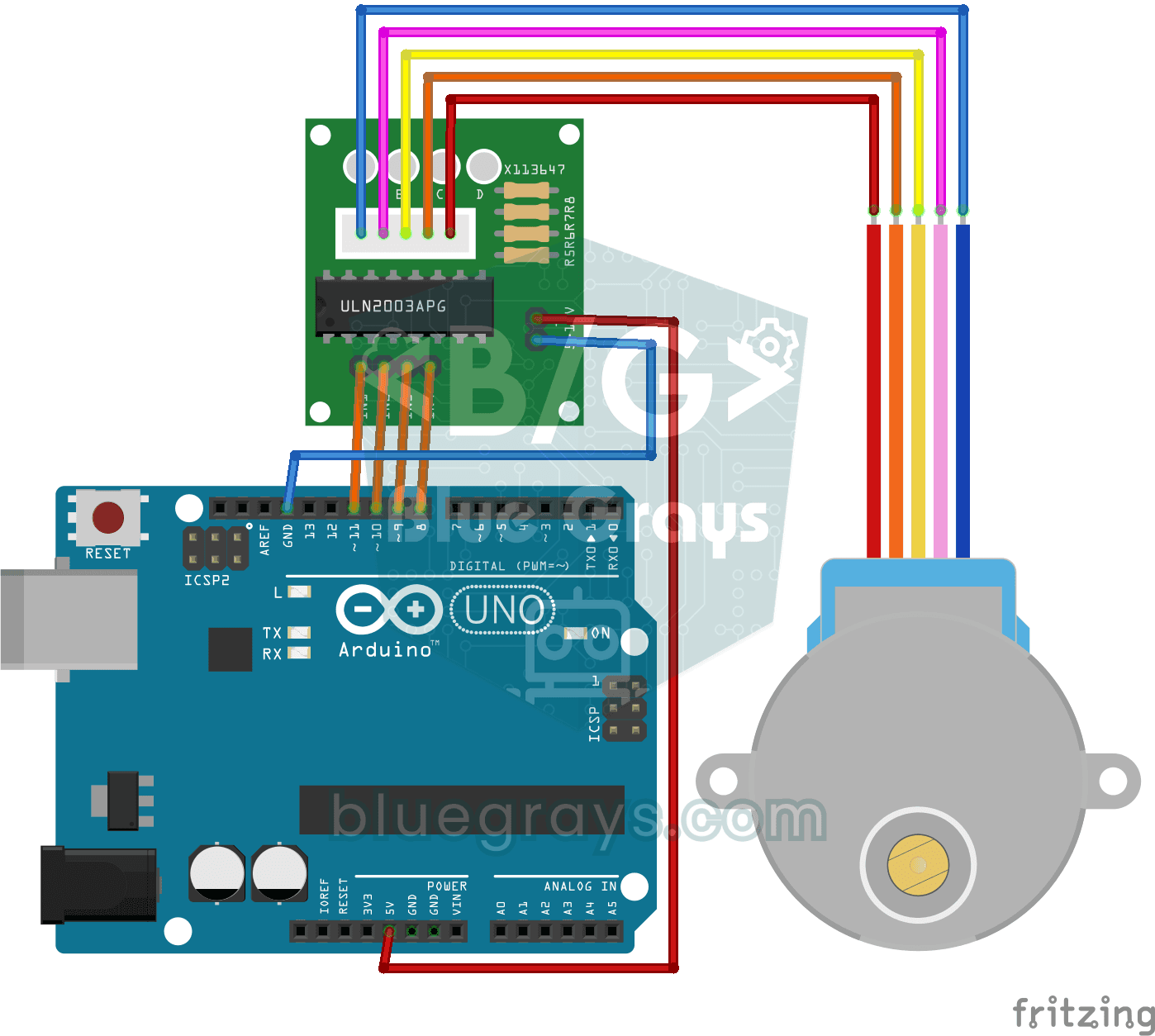
Using a Stepper Motor
A motor that turns step by step, exactly as far as you want, like the hand of a clock.
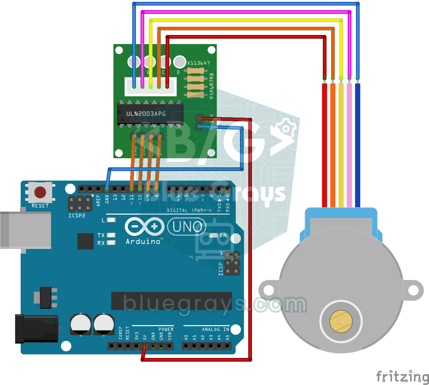
360-Degree Servo from a Stepper Motor
Teach an ordinary stepper motor to go to any angle you want, all the way around the circle.

Smart Irrigation Station
A gardener that waters your plants on its own, so they don't dry out while you're on vacation.

ESP32 LED Fade with PWM
Smoothly changing the brightness of the LED from 0 to max, from max to 0. We control PWM with analogWrite() as in Arduino - the same syntax as ESP32 Arduino Core 3.0+ works without problems. Pin definition + pinMode + analogWrite is enough.
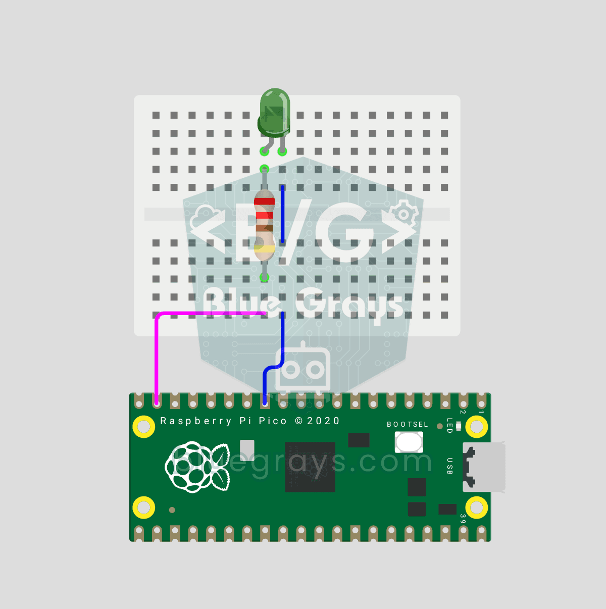
Raspberry Pi Pico PWM LED Fade (Breathing Effect)
The LED doesn't just blink anymore, it breathes! With the Raspberry Pi Pico's PWM (Pulse Width Modulation), the LED's brightness slowly rises and then slowly fades, a calm "breathing" effect like a sleeping laptop's light. You'll learn the machine.PWM class, the 16-bit brightness value from 0–65535 with duty_u16() and the PWM frequency.