
18650 Battery Guide: Voltage, Capacity, Charging and ESP32
What is an 18650 Li-Ion cell? The 3.0–4.2 V range, real capacity, protected vs unprotected, spotting fakes, TP4056 charging, BMS and powering ESP32, Pico, Arduino.

The 18650 battery is a cylindrical lithium-ion (Li-Ion) cell, 18 mm in diameter and 65 mm long. You'll find it everywhere, from laptop battery packs and e-bikes to flashlights and portable ESP32 sensor projects. A single cell gives 4.2 V when fully charged and about 3.0 V when empty, and good models offer 2500–3500 mAh. The numbers in the name describe its size: 18 mm diameter, 65 mm length, and the final 0 means a cylindrical body.
In this guide you'll learn the 18650's voltage range and how to estimate remaining charge from voltage, the real capacity values, the difference between protected and unprotected cells, and how to tell a fake cell from a real one. Then we'll go step by step through safe charging with the TP4056 module, powering an ESP32, Raspberry Pi Pico and Arduino with a battery holder, code that measures battery voltage, why a BMS is essential for series packs, and the safety rules you must follow.
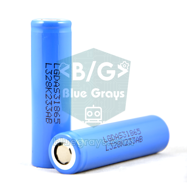
What is an 18650 battery and how does it work?
In a Li-Ion cell, lithium ions move from the cathode (usually nickel-manganese-cobalt or nickel-cobalt-aluminium oxide) to the graphite anode during charging, and move back during discharge. The cell's voltage depends on this chemistry and varies over a wide range: charging above 4.2 V or discharging below 2.5 V permanently damages the electrodes, causes heating and, in the worst case, fire. So when working with an 18650, always keep two limits in mind: a maximum of 4.20 V when charging and a minimum of 3.0 V when discharging. As long as you stay between these limits, the cell works safely for hundreds of cycles.
| Feature | Value |
|---|---|
| Size | 18 mm diameter, 65 mm length (protected cells 67–70 mm) |
| Chemistry | Li-Ion (mostly NMC or NCA); LiFePO4 versions are 3.2 V nominal |
| Nominal voltage | 3.6–3.7 V |
| Fully charged voltage | 4.20 V (±0.05 V) |
| End of discharge | 2.5–3.0 V (in practice, stop at 3.0 V) |
| Real capacity | 1800–3600 mAh |
| Weight | About 44–50 g |
| Continuous discharge current | Roughly 5–20 A depending on the cell model |
| Standard charge current | 0.5C (1.5 A for 3000 mAh); 0.5–1 A is enough for hobby use |
| Charging temperature | 0–45 °C |
| Cycle life | 300–1000 cycles (until capacity drops to 80%) |
Capacity is expressed in mAh (milliamp-hours) and tells you how long the cell can supply current. A 3000 mAh battery can theoretically deliver 3000 mA for one hour or 300 mA for ten hours. To compare energy, Wh is more accurate: 3.0 Ah × 3.7 V ≈ 11.1 Wh. Here's a real example: an ESP32 with Wi-Fi on draws about 100 mA on average. Powered through a low-dropout regulator, it also draws about 100 mA from the battery; taking the safely usable 80% of 3000 mAh into account, the run time is 3000 × 0.8 / 100 ≈ 24 hours. You can do this calculation for your own circuit with the battery life calculator, and read the details of mAh in the mAh battery capacity post. There's also a trade-off between capacity and current: high-capacity 3500 mAh cells such as the Samsung 35E give at most 8 A, while high-drain 2500 mAh cells such as the Samsung 25R handle 20 A. In microcontroller projects the current is low, so choosing a high-capacity cell makes sense; in motor-driven robots, look at the current rating first.
18650 voltage range: full, empty and percentage table
A Li-Ion cell's voltage drops as the remaining charge falls, but not linearly: it falls quickly from 4.2 V to 3.9 V, stays flat for a long time between 3.8 and 3.6 V, and then collapses suddenly below 3.5 V. The table below gives approximate values for a rested battery, one that has been under no load for at least half an hour. Under load, internal resistance makes the voltage read 0.1–0.2 V lower; measuring when the load is light improves the estimate. We'll use the same table in the Arduino, ESP32 and Pico code below.
| Rested cell voltage | Approx. charge | What it means |
|---|---|---|
| 4.20 V | 100% | Just off the charger, fully charged |
| 4.00 V | ~78% | Comfortable use zone |
| 3.80 V | ~52% | Half full; the ideal range for long-term storage |
| 3.70 V | ~38% | Around the nominal voltage |
| 3.60 V | ~22% | Time to charge is getting close |
| 3.40 V | ~5% | Almost empty; consider shutting the project down |
| 3.00 V | 0% | End of discharge; charge immediately |
| Below 2.50 V | - | Deep discharge; the cell may be permanently damaged |
Protected vs unprotected 18650
A protected 18650 carries a small circuit board at the negative end of the cell. This board cuts off charging if the cell reaches 4.25–4.3 V, cuts off discharge if it falls to 2.4–2.5 V, and stops the current within milliseconds in a short circuit. The price is a few extra millimetres of length and a somewhat lower current limit. An unprotected cell is bare; the protection has to come from the external circuit, that is, the DW01 chip on a TP4056 module or a BMS board. In single-cell hobby projects, and especially in your first experiments, using a protected cell or a protected charging module acts as a strong fuse against mistakes.
| Feature | Protected | Unprotected |
|---|---|---|
| Construction | Small protection board under the cell (e.g. DW01 + 8205 MOSFET) | Bare cell |
| Length | 67–70 mm, hard to fit in some holders | 65 mm |
| Overcharge protection | Yes (~4.25–4.3 V) | No |
| Over-discharge protection | Yes (~2.4–2.5 V) | No |
| Short circuit and overcurrent | Yes | No |
| Positive end | Usually button top | Flat top or button top |
| Typical use | Single-cell hobby projects, flashlights | Packs with a BMS, high-current applications |
How to spot a fake 18650 battery
- Impossible capacity: The highest-capacity genuine 18650 cells on the market today are about 3500–3600 mAh. A cell labelled 4800, 6800 or 9900 mAh is definitely fake; when measured, most come out at 500–1200 mAh.
- Weight: A genuine 18650 weighs 44–50 g. A cell that weighs under 35 g on a kitchen scale is either hollow or a smaller cell wrapped in a sleeve.
- Name and price: Cells sold under names like UltraFire or GTF, with colourful "fire"-themed wraps and at half the market price, are notorious for counterfeiting. Trustworthy cells are made by Samsung, LG, Sony/Murata, Panasonic and Molicel.
- Wrap and printing: Genuine cells have a clean wrap with a printed model and production code. A wrinkled, bulging or double-layered wrap can show that salvaged cells have been re-wrapped.
- Capacity test: The most reliable method is to discharge the cell from 4.2 V to 3.0 V at a constant current such as 0.5 A with a charger that has a discharge function, and measure it. A new cell that delivers less than 80% of its label is either fake or worn out.
- Internal resistance: Good new cells have an internal resistance of a few tens of milliohms. A cell whose voltage collapses quickly under load and which heats up fast is weak; such cells cause resets and heating in motor projects.
- Safety risk: In some fake cells the protection board exists only in appearance and the internal separator layer is poor quality; so buying a cheap cell endangers not only run time but safety too.
Charging an 18650 with the TP4056
The TP4056 is a cheap chip that charges a single Li-Ion cell the right way: first constant current (CC), then constant voltage (CV). It runs from a 5 V USB source, fills the cell to 4.2 V at an adjustable current, gradually reduces the current when the voltage reaches 4.2 V, and ends charging when the current falls to one-tenth of the set value. The red LED shows charging is in progress, and the blue or green LED shows it's finished. When buying a module, be careful: the six-pad version (IN+, IN-, B+, B-, OUT+, OUT-) has a DW01 protection chip and an 8205 MOSFET; you connect the cell to B+ and B- and your circuit to OUT+ and OUT-. The cheap four-pad version has no protection. The charge current is set by the R_PROG resistor on the board (approximate formula: I = 1200 / R_PROG, current in amps, resistance in ohms). The factory setting is 1.2 kΩ, i.e. 1 A; for small-capacity or old cells you can change this resistor to lower the current. The SMD code calculator helps you read the resistor's value from its SMD code; the module is covered in full in the TP4056 charging module post.
| R_PROG | Charge current | Recommended use |
|---|---|---|
| 10 kΩ | 130 mA | Small LiPo cells, testing |
| 5 kΩ | 250 mA | Cells of around 500 mAh |
| 2 kΩ | 580 mA | Old or low-capacity 18650 |
| 1.5 kΩ | 780 mA | General use |
| 1.2 kΩ (factory) | 1000 mA | Healthy 18650 above 2000 mAh |
Powering ESP32, Pico and Arduino with a battery holder
An 18650 battery holder keeps the cell with spring contacts without soldering and gives two wire outputs; red is positive and black is negative. Before inserting the cell, check the plus (+) mark inside the holder; a cell inserted backwards can burn the connected circuit in seconds if there's no protection. The real issue is voltage: a single cell swings between 3.0 and 4.2 V, which suits neither 3.3 V nor 5 V directly. The Raspberry Pi Pico is the luckiest board here, because its VSYS pin accepts 1.8–5.5 V and the on-board buck-boost converter produces a steady 3.3 V even as the cell drains. The AMS1117 regulator on ESP32 development boards, on the other hand, needs about 1 V of dropout; with a single cell the 3V3 rail falls to 2.7–3.1 V and brownout resets begin when Wi-Fi starts. The Arduino Uno's VIN input expects 7–12 V, so it doesn't work with a single cell at all; you either make 5 V with an MT3608 boost converter and feed the 5V pin, or connect two cells in series.
| Board | 18650 connection | Why? |
|---|---|---|
| Raspberry Pi Pico | Cell + → Schottky diode → VSYS (pin 39), Cell – → GND | VSYS accepts 1.8–5.5 V, the on-board buck-boost makes 3.3 V |
| ESP32 development board | Cell → low-dropout 3.3 V LDO (e.g. ME6211, RT9080) → 3V3 | Stable 3.3 V until the cell drops to about 3.5 V; the AMS1117 is bypassed |
| ESP32 (alternative) | Cell → MT3608 (5 V) → 5V/VIN | Easy to set up, lower efficiency (two conversions) |
| Arduino Uno | Cell → MT3608 (5 V) → 5V pin, or 2S pack + BMS → VIN/jack | VIN needs 7–12 V, a single cell isn't enough |
| Arduino Pro Mini 3.3 V / 8 MHz | Cell + → RAW, Cell – → GND | The on-board low-dropout regulator works with a single cell |
Measuring 18650 battery voltage with Arduino
Measuring battery voltage is necessary to show the remaining charge and to shut the circuit down safely before the cell runs out. The Arduino Uno's analog input measures 0–5 V; although a single cell's 4.2 V is within this range, halving the voltage with two 10 kΩ resistors both makes it easier to move to 2S packs and leaves a safety margin on the pin. The wiring is: cell positive → 10 kΩ → A0 → 10 kΩ → GND; the cell's negative must be connected to the Arduino's GND. The divider continuously draws 4.2 V / 20 kΩ ≈ 0.2 mA from the cell. The code averages 16 samples, finds the percentage by linear interpolation between the points in the table, and gives a warning below 3.0 V. On a USB-powered Uno the 5V rail is often between 4.7 and 5.0 V; if you replace VREF with the real value you measured with a multimeter, the error drops to a few tens of millivolts. You can change the resistor ratio with the voltage divider calculator and read the logic in the voltage divider post.
1// 18650 pil gerilimi ve yaklaşık şarj yüzdesi / 18650 cell voltage and approx. charge percent
2// Bağlantı: Pil+ -> 10k -> A0 -> 10k -> GND, Pil- -> GND / Wiring: Cell+ -> 10k -> A0 -> 10k -> GND, Cell- -> GND
3
4const int PIN_BAT = A0;
5const float VREF = 5.0;      // 5V pinini multimetreyle ölç, buraya yaz / measure the 5V pin, write it here
6const float DIVIDER = 2.0;   // (10k + 10k) / 10k
7
8const float voltTable[] = {4.20, 4.10, 4.00, 3.90, 3.80, 3.70, 3.60, 3.50, 3.40, 3.00};
9const int percentTable[] = {100, 90, 78, 65, 52, 38, 22, 10, 5, 0};
10const int TABLE_SIZE = sizeof(voltTable) / sizeof(voltTable[0]);
11
12float readBatteryVoltage() {
13  long sum = 0;
14  for (int i = 0; i < 16; i++) {   // 16 örnek ortalaması / average of 16 samples
15    sum += analogRead(PIN_BAT);
16    delay(2);
17  }
18  float raw = sum / 16.0;
19  return raw * VREF / 1023.0 * DIVIDER;
20}
21
22int voltageToPercent(float v) {
23  if (v >= voltTable[0]) return 100;
24  if (v <= voltTable[TABLE_SIZE - 1]) return 0;
25  for (int i = 0; i < TABLE_SIZE - 1; i++) {
26    if (v >= voltTable[i + 1]) {   // iki nokta arasında doğrusal ara değer / linear interpolation between two points
27      float pos = (v - voltTable[i + 1]) / (voltTable[i] - voltTable[i + 1]);
28      return percentTable[i + 1] + (int)(pos * (percentTable[i] - percentTable[i + 1]));
29    }
30  }
31  return 0;
32}
33
34void setup() {
35  Serial.begin(9600);
36}
37
38void loop() {
39  float v = readBatteryVoltage();
40  int p = voltageToPercent(v);
41  Serial.print(F("Pil / Battery: "));
42  Serial.print(v, 2);
43  Serial.print(F(" V  %"));
44  Serial.println(p);
45  if (v < 3.0) {
46    Serial.println(F("UYARI: Pil cok bos! / WARNING: cell is deeply discharged!"));
47  }
48  delay(1000);
49}
Battery monitoring with ESP32 and Raspberry Pi Pico
The ESP32's ADC input tolerates at most 3.3 V and, with the default 11 dB attenuation, measures accurately up to about 3.1 V; so a divider is mandatory here. To avoid wasting current from the cell, use 100 kΩ + 100 kΩ, connect the midpoint to GPIO 34, and add a 100 nF capacitor from the same point to GND to stabilise the reading. GPIO 34 belongs to the ADC1 group and works while Wi-Fi is on; ADC2 pins can't be used together with Wi-Fi. The analogReadMilliVolts() function we use in the code gives millivolts directly using the chip's factory calibration and works the same way in versions 2.x and 3.x of the ESP32 Arduino core. The program measures the cell; if the voltage is below 3.3 V it goes to sleep so that only a reset wakes it, otherwise it enters a 10-minute deep sleep.
1#include <Arduino.h>
2#include "esp_sleep.h"
3
4// Bağlantı: Pil+ -> 100k -> GPIO34 -> 100k -> GND, GPIO34 -> 100nF -> GND
5// Wiring: Cell+ -> 100k -> GPIO34 -> 100k -> GND, GPIO34 -> 100nF -> GND
6
7const int PIN_BAT = 34;               // ADC1 pini, Wi-Fi ile çalışır / ADC1 pin, works with Wi-Fi
8const float DIVIDER = 2.0;            // 100k + 100k bölücü / 100k + 100k divider
9const float LOW_CUTOFF = 3.30;        // bu değerin altında kapan / shut down below this voltage
10const uint64_t SLEEP_US = 10ULL * 60ULL * 1000000ULL;   // 10 dakika / 10 minutes
11
12float readBatteryVoltage() {
13  uint32_t sum = 0;
14  for (int i = 0; i < 32; i++) {
15    sum += analogReadMilliVolts(PIN_BAT);   // kalibre edilmiş mV / calibrated mV
16    delay(1);
17  }
18  return (sum / 32.0) * DIVIDER / 1000.0;
19}
20
21void setup() {
22  Serial.begin(115200);
23  delay(100);
24
25  float v = readBatteryVoltage();
26  Serial.printf("Pil / Battery: %.2f V\n", v);
27
28  if (v < LOW_CUTOFF) {
29    Serial.println("Pil zayif, kapaniyor / Battery low, shutting down");
30    Serial.flush();
31    esp_deep_sleep_start();           // uyanma kaynağı yok: yalnız reset / no wake source: reset only
32  }
33
34  // Burada sensör oku ve Wi-Fi ile gönder / Read sensors and send over Wi-Fi here
35
36  esp_sleep_enable_timer_wakeup(SLEEP_US);
37  Serial.println("10 dk uyku / sleeping 10 min");
38  Serial.flush();
39  esp_deep_sleep_start();
40}
41
42void loop() {
43}
No extra components are needed on the Raspberry Pi Pico: the board divides VSYS by 3 internally and connects it to ADC3 (GP29), and GP24 tells you whether USB is plugged in. If you put a Schottky diode such as the 1N5819 between the cell and VSYS, it stops USB from pushing current into the cell when USB and battery are connected at the same time; in this case VSYS reads 0.2–0.3 V lower than the cell voltage, and the code compensates for this with the DIODE constant. The code below is for the standard Pico; on the Pico W, GP29 is shared with the wireless chip, so the measurement needs extra setup. If you're new to MicroPython, first take a look at the What is the Raspberry Pi Pico post.
1from machine import ADC, Pin
2import time
3
4vsys = ADC(29)            # ADC3 = VSYS/3 (standart Pico) / VSYS/3 (standard Pico)
5usb = Pin(24, Pin.IN)     # 1 ise USB takılı / 1 when USB is connected
6led = Pin(25, Pin.OUT)    # dahili LED / onboard LED
7
8DIODE = 0.25              # Schottky diyot düşümü, diyot yoksa 0 / Schottky drop, 0 without diode
9VOLTS = (4.20, 4.10, 4.00, 3.90, 3.80, 3.70, 3.60, 3.50, 3.40, 3.00)
10PERCENT = (100, 90, 78, 65, 52, 38, 22, 10, 5, 0)
11
12def read_vsys():
13    total = 0
14    for _ in range(16):               # 16 örnek ortalaması / average of 16 samples
15        total += vsys.read_u16()
16        time.sleep_ms(2)
17    return total / 16 * 3.3 / 65535 * 3
18
19def percent(v):
20    if v >= VOLTS[0]:
21        return 100
22    if v <= VOLTS[-1]:
23        return 0
24    for i in range(len(VOLTS) - 1):
25        if v >= VOLTS[i + 1]:         # doğrusal ara değer / linear interpolation
26            pos = (v - VOLTS[i + 1]) / (VOLTS[i] - VOLTS[i + 1])
27            return int(PERCENT[i + 1] + pos * (PERCENT[i] - PERCENT[i + 1]))
28    return 0
29
30while True:
31    v = read_vsys()
32    if usb.value():
33        led.off()
34        print("USB bagli / USB powered: VSYS = %.2f V" % v)
35    else:
36        bat = v + DIODE
37        print("Pil / Battery: %.2f V  %%%d" % (bat, percent(bat)))
38        if bat < 3.3:
39            led.toggle()              # pil zayıf uyarısı / low battery warning
40        else:
41            led.off()
42    time.sleep(2)
Why are series connection and a BMS essential?
For higher voltage, cells are connected in series: a 2S pack gives 7.4 V nominal, 8.4 V fully charged and 6.0 V empty; a 3S pack has 11.1 V nominal and 12.6 V fully charged. Parallel connection doesn't change the voltage but adds the capacity: two 3000 mAh cells in parallel make 3.7 V and 6000 mAh. The problem in a series pack is that over time the cells charge and discharge at different rates. A charger that looks at the total voltage sees 8.4 V, but inside, one cell may have reached 4.35 V while the other is at 4.05 V; the overcharged cell heats up and becomes dangerous. A BMS (Battery Management System) board monitors each cell separately and cuts the circuit on overcharge, over-discharge and overcurrent; those with balancing equalise the cells by discharging the full cell through a small resistor. So in a series pack, always use a BMS matched to the number of cells and a CC/CV charger that outputs 8.4 V or 12.6 V. The TP4056 is for a single cell only; feeding two TP4056 modules from the same source and connecting them to series cells creates a short circuit. Before connecting in parallel, bring the cells' voltage difference below 0.1 V and use cells of the same brand, model and age. For detailed calculations, see the connecting batteries in series and parallel post.
18650 battery project ideas
- Portable weather station: send data for weeks from a single 18650 cell with an ESP32, a BME280, deep sleep and a board with low sleep current.
- Display with battery gauge: show the measured voltage and percentage with a battery icon on an OLED display.
- Rechargeable desk lamp: build a lamp that charges over USB with a TP4056, an MT3608 and a few WS2812B LEDs; remember that each LED draws up to 60 mA at full white.
- Robot car: power the motors of a robot car through an L298N with a 2S pack and a BMS.
- Battery capacity tester: discharge the cell at about 0.37 A with an Arduino, a MOSFET and a 10 Ω 5 W resistor, multiply the elapsed time by the current to find the real mAh, and check the power the resistor dissipates with the Ohm's law calculator.
- Pico data logger: build a portable logger with a Pico and an SD card module that records temperature and closes the file by measuring VSYS before the cell runs out.
Safety rules
- Watch out for short circuits: an 18650 cell delivers tens of amps in a short circuit; even a thin wire can glow red and melt. Don't carry cells in a pocket or in the same bag as keys; use a plastic storage case.
- Check the wrap: the whole metal body of the cell is the negative terminal, and a thin insulating ring around the positive end separates the two poles. A torn wrap causes a short circuit when it touches the holder's metal part; don't use a cell with a damaged wrap without having it re-wrapped.
- Don't solder directly: soldering iron heat damages the separator and the safety vent inside the cell. Use a battery holder, a cell with ready solder tabs, or a nickel strip that is spot-welded.
- Charging conditions: never charge below 0 °C, and stop charging in environments above 45 °C. In your first trials stay with it while it charges and put the module on a non-flammable surface.
- Retire a damaged cell: don't use a cell that is swollen, crushed, leaking, too hot to touch while charging, or that has sat below 2 V for a long time; drop it in a battery recycling bin.
- Store correctly: store a cell you won't use for a long time at around 3.7–3.8 V in a cool, dry place; keeping it fully charged or fully empty shortens its life.
Common mistakes and how to fix them
| Symptom | Likely cause | Fix |
|---|---|---|
| ESP32 keeps resetting while connecting to Wi-Fi | The 3V3 rail drops below 3 V because of the AMS1117's dropout | Use a low-dropout LDO or an MT3608, and add a 100–470 µF capacitor between 3V3 and GND |
| TP4056's red LED never goes off | The load stayed connected to the OUT pads, or the cell is worn out or fake | Disconnect the load while charging, test the cell's capacity |
| Cell reads 0 V | The protection circuit cut the cell off after over-discharge | Plugging it into the charging module usually reactivates the protection; don't use a bare cell that is below 2 V |
| Protected cell doesn't make contact or doesn't fit in the holder | Protected cells are 67–70 mm long | Use a long-type holder, or an unprotected cell + a protected charging module |
| Percentage value keeps jumping | Voltage fluctuates under load, the ADC is noisy | Average 16–32 samples, add 100 nF at the divider output, measure when the load is light |
| Arduino Uno won't start on a battery at all | A single cell is too low for VIN | Feed the 5V pin with an MT3608, or use a 2S pack + BMS |
| Cell gets too hot to touch while charging | Charge current is too high for the cell, or the cell is damaged | Stop charging immediately, lower the current with R_PROG, and discard the cell if it still heats up |
With proper charging, the right regulator and a few safety rules, the 18650 is the most practical way to free your projects from the cable. When you use a TP4056 and a protected cell for a single cell, and a BMS and a suitable charger for a series pack, you stay safe. You can compare all the power options in the Arduino power supply guide. In the BlueGrays app you'll find ESP32 deep sleep battery saving, a digital voltmeter and Pico LED projects step by step with circuit diagrams and code, and you can make these projects easily portable with a battery holder and an 18650.
Frequently asked questions
How many volts is an 18650 battery?
The nominal voltage of an 18650 Li-Ion battery is 3.6–3.7 V. It measures 4.2 V when fully charged, and the end of discharge is usually taken as 3.0 V; you can estimate the remaining charge roughly from the voltage. LiFePO4 18650 cells work at 3.2 V nominal and 3.6 V fully charged.
How many mAh is an 18650 battery really?
18650 cells from trustworthy brands range from 1800 to 3600 mAh; the highest-capacity models are about 3500 mAh. Cells labelled 5000 or 9900 mAh are fake and usually measure below 1000 mAh. If one weighs under 40 g, you should be suspicious too.
Can I charge an 18650 with a phone charger?
You can't connect a phone charger directly to the cell; 5 V overcharges the cell and is dangerous. If you connect the charger to the USB input of a Li-Ion charging module such as the TP4056, the module safely charges the cell to 4.2 V with the correct CC/CV method. Ready-made 18650 chargers do the same job.
Should I buy a protected or unprotected 18650?
In single-cell hobby projects and flashlights, a protected cell gives extra safety against overcharge, over-discharge and short circuits. Unprotected cells are preferred in packs with a BMS and in high-current applications, because the protection is already in the circuit. Remember that protected cells are 67–70 mm and don't fit in some holders.
How do I power an ESP32 or Arduino with an 18650 battery?
For the ESP32, connect the cell to 3V3 through a low-dropout 3.3 V regulator, or boost it to 5 V with an MT3608 and feed the 5V pin; don't connect the cell directly to the 3V3 pin. For the Arduino Uno you need to make 5 V with an MT3608, or connect two cells in series and feed VIN through a BMS. The Raspberry Pi Pico accepts the cell directly on its VSYS pin.
Can an 18650 battery explode?
A quality 18650 is very safe when used correctly, but a short circuit, overcharging, puncture or overheating can cause fire and venting gas. Using a protected cell or a protected charging module, keeping the wrap intact, not charging below 0 °C and staying away from fake cells greatly reduces the risk.
Projects to build after reading this
See all projects
LED Blink with ESP32
Teaches basic GPIO output usage with ESP32. We achieve a blinking effect by turning an LED on and off from a digital pin. ESP32 version of the classic blink project on Arduino UNO; the basic blink commands in the Arduino environment are the same, but the ESP32's pin layout and 3.3 V GPIO levels differ from those of the Arduino UNO.

ESP32 Built-in LED Blink
Blinking the built-in blue LED on the ESP32 DevKit V1. No external components required! The first project you should try when you buy an ESP32. GPIO 2 is connected to the built-in LED.

Reading Light Intensity with the ESP32 LDR Module
Real-time monitoring of the LDR module's raw ADC value and relative light percentage calculated from dark and light reference values in the Serial Monitor. This percentage is not a lux measurement. Teaches the module’s calibration logic. It is ideal to complete this before Project 10, as it is used to determine the threshold value.
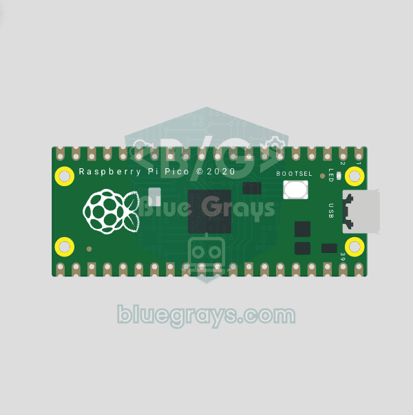
Raspberry Pi Pico Onboard LED Blink (Pico and Pico W)
The opening project of the Raspberry Pi Pico series! We blink the Pico's green built-in LED to confirm the board works, the classic "Hello World" first experiment. No external parts needed, just the Pico and a USB cable. The code is written in MicroPython, the language officially supported by the Raspberry Pi Foundation.
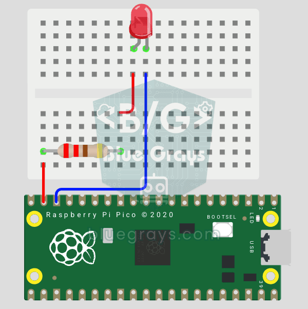
Raspberry Pi Pico: Controlling an External LED (Breadboard)
The next step after the Pico's built-in LED: connect an external LED on a breadboard and control it through pin GP14. You'll learn how to use any of the Pico's GPIO pins as an output, the LED's polarity (long leg = anode/+, short leg = cathode/–) and why a current-limiting resistor (220Ω) is a must. Without the resistor, too much current flows through the LED and it can burn out.

ESP32 Deep Sleep — Battery Saving (OLED + RTC RAM Counter)
The ESP32's Deep Sleep mode shuts down the CPU and most peripherals, cutting current draw to about 10µA, which is vital for battery-powered IoT devices. This project uses three wake-up sources: a timer (15 s), an external pin (EXT0, the button on GPIO 33) and a touch pin (T0/GPIO 4). Counters marked with RTC_DATA_ATTR survive deep sleep.
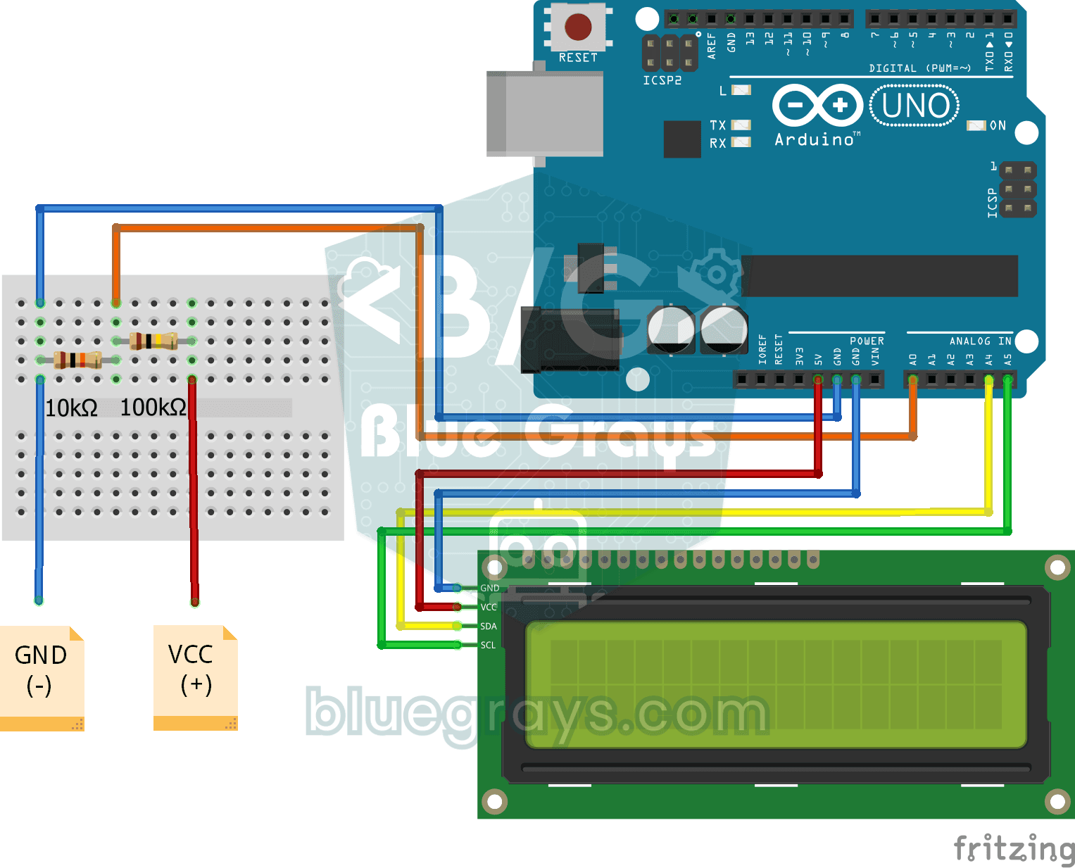
Digital Voltmeter with LCD Display
Find out how much voltage a battery or power adapter gives with a meter you built yourself.
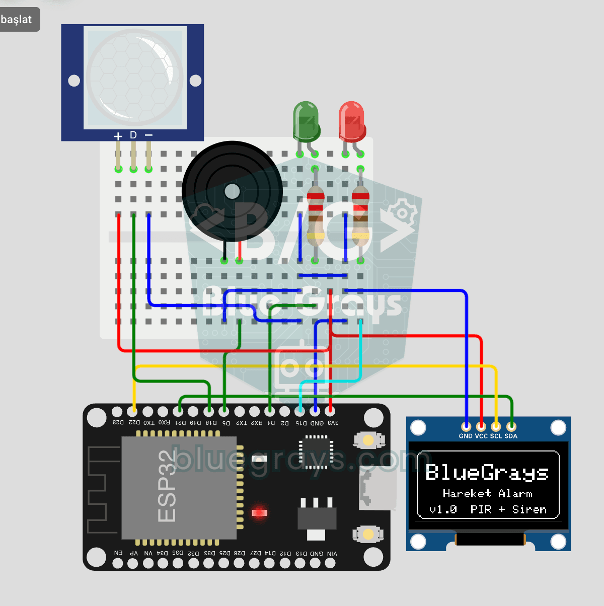
ESP32 Motion Alarm System (PIR + Buzzer + LED + Telegram)
A smart security alarm: when the PIR sensor detects motion, it sounds the buzzer, lights the LED and sends the owner an instant Telegram notification. A 30-second cooldown limits how often the alarm repeats; it does not filter out the PIR sensor's false detections. Use it at home, in a garage, a storeroom or a study.