
A4988 Stepper Driver with NEMA 17: Vref, Microstepping, Code
How to drive a NEMA 17 with the A4988: STEP/DIR wiring, the Vref formula, setting current with a multimeter, MS1–MS3 microstepping, AccelStepper and CNC Shield.
Driving a NEMA 17 with the A4988 is the cheapest way to bring the precise motion used by 3D printers, CNC machines and laser engravers into your own project. The A4988 is a bipolar stepper motor driver made by Allegro and sold on a fingertip-sized module: every STEP pulse from the Arduino moves the motor one step, the DIR pin chooses the direction, and the driver holds the current through the motor coils at the value you set. In other words, all you need to turn the motor is two pins and a power supply between 8 and 35 V.
In this guide you'll learn how the A4988 works, how to find the coils of a NEMA 17 with a multimeter, how to wire it, and why you need a 100 µF capacitor on the supply. Then we'll move on to the most critical step, setting the current with Vref, working through the formula and the multimeter measurement step by step. Microstepping with the MS1–MS3 pins, a first sketch without a library, smooth acceleration with AccelStepper, the CNC Shield, ESP32 and Raspberry Pi Pico code, heat and heat sinks, a DRV8825 and TMC2208 comparison and fixes for the classic "motor vibrates but doesn't turn" problem are all here too.
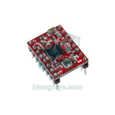
What is the A4988 and how does it work?
Inside the A4988 are two full H-bridges (one per coil), a translator and a current control circuit. The translator turns every LOW→HIGH transition on the STEP pin into the right current sequence for the coils, so you don't have to work out the coil order in your code. Current control uses a chopper: the driver constantly monitors each coil's current through a small sense resistor (Rs) and briefly switches the output off whenever the current reaches the set limit. That's why the coil current stays at a safe value even if you power the motor well above its rated voltage, for example from 12 or 24 V. The chip also has protection against overheating, undervoltage, shorted loads and shorts to ground.
| Feature | Value |
|---|---|
| Motor supply (VMOT) | 8–35 V |
| Logic supply (VDD) | 3–5.5 V (5 V on Arduino, 3.3 V on ESP32 and Pico) |
| Current per coil | About 1 A without a heat sink, up to 2 A with good cooling |
| Microstepping | Full, 1/2, 1/4, 1/8, 1/16 |
| Control pins | STEP, DIR, ENABLE, MS1–MS3, RESET, SLEEP |
| STEP pulse | HIGH and LOW parts at least 1 µs each |
| Protection | Thermal shutdown (165 °C), undervoltage lockout, short-circuit protection |
| Suitable motors | 4-wire bipolar stepper motors (NEMA 17, NEMA 14, etc.) |
NEMA 17 stepper motor: specs and finding the coils
NEMA 17 isn't a motor model but a size standard for motors with a 42 × 42 mm faceplate; what's inside depends on the body length and the manufacturer. The 17HS4401, the most common model in hobby projects, makes 200 steps per revolution (1.8°), has a rated current of 1.7 A per phase, a coil resistance of about 1.5 Ω and roughly 40 N·cm of holding torque. The voltage on its label is only 1.7 A × 1.5 Ω ≈ 2.6 V, but don't let that fool you: because the A4988 limits the current itself, the motor is powered from 12–24 V. A higher voltage lets the coil current rise faster on every step, so the motor loses less torque at high speed. If you're curious how it differs from small unipolar motors such as the 28BYJ-48, see 28BYJ-48 and ULN2003.
The motor's 4 wires belong to two independent coils, and before you connect it to the A4988 you need to know which two wires form the same coil. On many models black-green is one coil and red-blue the other, but colours vary between manufacturers, so the most reliable way is to measure:
- Set your multimeter to resistance (Ω); if you're not sure how, take a look at the multimeter guide.
- Hold one wire and measure it against each of the other three. The wire that reads 1–4 Ω is the other end of the same coil; the other two show an open circuit (OL).
- The remaining two wires are the second coil and should show the same resistance. With the measured resistance and the rated current you can check the motor's label voltage using the Ohm's law calculator.
- No multimeter? Touch the ends of two wires together and turn the shaft by hand: if it becomes noticeably harder to turn, those two wires are the same coil.
- Connect one coil to the A4988's 1A–1B pins and the other to 2A–2B. If the motor turns the opposite way to what you want, just swap the two wires of one coil.
A4988 pinout and wiring diagram
| A4988 pin | Arduino Uno | ESP32 | Raspberry Pi Pico |
|---|---|---|---|
| VMOT | 12–24 V adapter positive (+ 100 µF) | 12–24 V adapter positive (+ 100 µF) | 12–24 V adapter positive (+ 100 µF) |
| GND (next to VMOT) | Adapter negative | Adapter negative | Adapter negative |
| 1A, 1B | Motor coil 1 | Motor coil 1 | Motor coil 1 |
| 2A, 2B | Motor coil 2 | Motor coil 2 | Motor coil 2 |
| VDD | 5V | 3V3 | 3V3 (OUT) |
| GND (next to VDD) | GND | GND | GND |
| STEP | D2 | GPIO 25 | GP2 |
| DIR | D5 | GPIO 26 | GP3 |
| ENABLE | D8 | GPIO 27 | GP4 |
| MS1, MS2, MS3 | 5V (1/16 step) | 3V3 (1/16 step) | 3V3 (1/16 step) |
| RESET, SLEEP | Bridge them together | Bridge them together | Bridge them together |
Why is a 100 µF capacitor a must?
A4988 boards only carry small ceramic capacitors. Combined with the inductance of the power leads, these low-ESR capacitors cause voltage spikes when you switch the supply on or when the motor draws a sudden current. These spikes can exceed the chip's 35 V limit even with a 12 V supply and damage the driver permanently. The fix is simple: put an electrolytic capacitor of at least 47 µF, ideally 100 µF, across VMOT and GND, as close to the board as possible. Its voltage rating should be comfortably above the supply voltage: choose 25 V for a 12 V supply, and 35 V or 50 V for 24 V. Electrolytic capacitors are polarised; the long leg (+) goes to VMOT and the short leg (–), marked by the stripe on the body, goes to GND. For capacitor types see What Is a Capacitor?, and to choose the right adapter see powering an Arduino.
Setting the current with Vref: the formula
The small potentiometer on the A4988 sets Vref (the reference voltage), which determines the maximum motor current. The driver compares this voltage with the voltage across the two sense resistors (Rs) on the board, and the peak coil current is given by: I = Vref / (8 × Rs). To find the Vref you need, rearrange it: Vref = I × 8 × Rs. To find Rs, read the marking on the two small SMD resistors next to the chip: R100 means 0.1 Ω, R068 means 0.068 Ω and R050 means 0.05 Ω. If you struggle with the codes, use the SMD resistor code calculator or the article on SMD resistor codes.
| Rs marking | Rs value | Formula | Vref for 0.8 A | Vref for 1 A | Vref for 1.2 A |
|---|---|---|---|---|---|
| R050 | 0.05 Ω | Vref = I × 0.4 | 0.32 V | 0.40 V | 0.48 V |
| R068 | 0.068 Ω | Vref = I × 0.544 | 0.44 V | 0.54 V | 0.65 V |
| R100 | 0.1 Ω | Vref = I × 0.8 | 0.64 V | 0.80 V | 0.96 V |
Which current should you choose? The current on the motor's label (1.7 A for the 17HS4401) is a ceiling you should never exceed. Without a heat sink the A4988 comfortably handles about 1 A, so 0.8–1 A is a good starting point. On common boards with R100 resistors that means a Vref of 0.64–0.80 V. If the motor skips steps under load, raise the current in 0.1 A increments; if you go above 1.2 A, add a heat sink and a fan to the chip. More current than you need heats the driver and the motor far more than it makes the motor noticeably stronger.
Measuring Vref with a multimeter: step by step
- With all power off, disconnect the motor from the driver. You don't need the motor to measure Vref.
- Power the A4988's VDD and GND pins with the logic supply (the Arduino's 5V is enough). Vref is derived from this voltage, so you can't measure it without VDD; keeping VMOT connected does no harm.
- Set the multimeter to DC voltage (2 V or 20 V range). Touch the black probe to GND and the red probe to the metal top of the potentiometer; some boards have a small test point labelled VREF instead.
- Turn the potentiometer very slightly with a small plastic or ceramic screwdriver and watch the reading. On most boards clockwise increases Vref, but this can vary; some potentiometers wrap around after a full turn, so go in small steps.
- When you reach the calculated value, switch the power off, connect the motor, and only then power it up again.
- Run the motor for a few minutes and check the chip's temperature. If you can't keep your finger on it even for a few seconds, lower Vref a little or add a heat sink.
Microstepping with MS1, MS2 and MS3
Microstepping means the driver changes the current in the two coils gradually, splitting each full step into smaller parts. The A4988 selects one of five modes based on the logic levels on the MS1–MS3 pins. These pins have internal pull-down resistors, so if you leave all three unconnected the motor runs in full-step mode.
| MS1 | MS2 | MS3 | Mode | Steps per revolution | Step angle |
|---|---|---|---|---|---|
| LOW | LOW | LOW | Full step | 200 | 1.8° |
| HIGH | LOW | LOW | Half step | 400 | 0.9° |
| LOW | HIGH | LOW | 1/4 step | 800 | 0.45° |
| HIGH | HIGH | LOW | 1/8 step | 1600 | 0.225° |
| HIGH | HIGH | HIGH | 1/16 step | 3200 | 0.1125° |
The real benefit of microstepping is smooth, quiet rotation: in full-step mode the motor jerks on every step and resonates and vibrates at certain speeds, while at 1/16 the motion is almost continuous. But don't expect the precision to really improve 16-fold. The torque that advances a single microstep is only sin(90° / 16) ≈ 10% of the holding torque; if friction or load overcomes that small force, the motor lags a few microsteps behind. To calculate speed, use: steps/s = RPM × 200 × microsteps / 60. For example, 60 RPM at 1/16 needs 3200 STEP pulses per second. If you want to change the mode in software you can wire the MS pins to the Arduino too; in most projects, though, selecting a fixed mode with wires is enough.
First sketch: turning the motor with STEP and DIR, no library
The sketch below turns the motor one revolution forward and one back without any library, just by sending pulses to the STEP pin. We assume you've connected MS1–MS3 to 5V, so the motor runs at 1/16 and one revolution is 3200 steps.
1// A4988 + NEMA 17, kütüphanesiz / without a library
2const int STEP_PIN = 2;            // CNC Shield X ekseniyle aynı / same as CNC Shield X axis
3const int DIR_PIN  = 5;
4const int EN_PIN   = 8;            // aktif LOW / active LOW
5
6const long STEPS_PER_REV = 200L * 16;   // 1,8° motor, 1/16 mikro adım = 3200 / 1.8° motor, 1/16 microstep
7
8void setup() {
9  pinMode(STEP_PIN, OUTPUT);
10  pinMode(DIR_PIN, OUTPUT);
11  pinMode(EN_PIN, OUTPUT);
12  digitalWrite(EN_PIN, LOW);       // sürücüyü aç / enable the driver
13}
14
15void rotate(long steps, unsigned int pauseUs) {
16  digitalWrite(DIR_PIN, steps > 0 ? HIGH : LOW);   // yön / direction
17  delayMicroseconds(5);                           // DIR, STEP'ten önce otursun / let DIR settle before STEP
18  for (long i = 0; i < labs(steps); i++) {
19    digitalWrite(STEP_PIN, HIGH);
20    delayMicroseconds(5);                         // darbe en az 1 µs / pulse at least 1 µs
21    digitalWrite(STEP_PIN, LOW);
22    delayMicroseconds(pauseUs);                   // küçüldükçe hız artar / smaller = faster
23  }
24}
25
26void loop() {
27  rotate(STEPS_PER_REV, 500);      // 1 tur ileri, ~1,6 sn / one turn forward, ~1.6 s
28  delay(1000);
29  rotate(-STEPS_PER_REV, 500);     // 1 tur geri / one turn back
30  delay(1000);
31}
There are three timings to watch in this code. The A4988 needs the HIGH and LOW parts of the STEP pulse to last at least 1 µs; 5 µs is a safe value. After DIR changes, you have to wait at least 200 ns before the first STEP pulse; the code waits 5 µs for this. Speed is set by the pause between pulses: with a 500 µs pause one step takes about 0.51 ms, so a revolution (3200 steps) takes about 1.6 seconds, roughly 36 RPM. This code has two weaknesses: the motor starts abruptly at full speed, and the Arduino can't do anything else while the loop runs. If you drop the pause straight to 100 µs, the motor will most likely fail to start and just buzz.
Acceleration and deceleration with AccelStepper
You can't take a stepper from standstill to high speed in an instant; the rotor and load can't keep up with such a sudden change, the motor loses sync and skips steps. The solution is to ramp the speed up and ramp it down as you approach the target. AccelStepper, which you can install from the Library Manager, does this without blocking: you call run() constantly inside loop() and the library takes a step whenever one is due. That way you can read buttons, update a display or take sensor readings while the motor turns; you'll find this approach in detail in millis() vs delay(). On an Uno, AccelStepper can reliably reach a few thousand steps per second (its documentation gives about 4000 steps/s at 16 MHz), so the example uses 2000 steps/s, which is about 37 RPM at 1/16.
1#include <AccelStepper.h>
2
3const int STEP_PIN = 2;
4const int DIR_PIN  = 5;
5const int EN_PIN   = 8;
6const long STEPS_PER_REV = 200L * 16;            // 1/16 mikro adımda 1 tur / one turn at 1/16 microstep
7
8AccelStepper stepper(AccelStepper::DRIVER, STEP_PIN, DIR_PIN);
9
10void setup() {
11  stepper.setEnablePin(EN_PIN);
12  stepper.setPinsInverted(false, false, true);   // EN aktif LOW / EN is active LOW
13  stepper.enableOutputs();
14  stepper.setMaxSpeed(2000);                     // adım/sn, Uno için güvenli / steps per second, safe on Uno
15  stepper.setAcceleration(1500);                 // adım/sn² / steps per second²
16  stepper.moveTo(STEPS_PER_REV * 3);             // 3 tur ileri / three turns forward
17}
18
19void loop() {
20  if (stepper.distanceToGo() == 0) {             // hedefe varıldı / target reached
21    delay(500);
22    stepper.moveTo(stepper.currentPosition() == 0 ? STEPS_PER_REV * 3 : 0);   // git-gel / back and forth
23  }
24  stepper.run();                                 // her döngüde çağır, bekletmez / call every loop, non-blocking
25}| Function | What it does |
|---|---|
| AccelStepper(AccelStepper::DRIVER, STEP, DIR) | Creates an object for a driver with STEP/DIR inputs |
| setMaxSpeed(steps/s) | The top speed to reach |
| setAcceleration(steps/s²) | The acceleration and deceleration rate |
| moveTo(position) / move(steps) | Go to an absolute position, or relative to where it is now |
| run() | Takes a step if one is due; must be called constantly inside loop() |
| runToPosition() | Blocks the program until the target is reached |
| distanceToGo() / currentPosition() | Steps remaining and the current position |
| setCurrentPosition(0) | Treats the current point as zero (after homing with a limit switch) |
| setEnablePin() / setPinsInverted() | Defines the EN pin; inverted because EN is active LOW on the A4988 |
| enableOutputs() / disableOutputs() | Energises or releases the coils |
Multiple motors with the CNC Shield V3
If you're driving more than one NEMA 17, the easiest way to avoid a tangle of wires is the Arduino CNC Shield V3. This board plugs onto the Uno and has four A4988 sockets (X, Y, Z and A), microstepping jumpers under each driver, motor headers, limit switch inputs and a power terminal; with all three jumpers fitted, the A4988 runs at 1/16. In the wiring table we deliberately chose D2, D5 and D8 for STEP, DIR and EN: these are the shield's X-axis pins, so the sketches above work on the shield unchanged. If you flash GRBL onto the Uno, the shield becomes a CNC or laser controller that takes G-code from your computer. In GRBL you enter how many steps each axis needs per millimetre in the $100, $101 and $102 settings: with a 20-tooth GT2 pulley and 1/16 microstepping that's 200 × 16 / (20 × 2) = 80 steps/mm, and on a T8 lead screw with an 8 mm lead it's 200 × 16 / 8 = 400 steps/mm.
| Axis | STEP | DIR | Note |
|---|---|---|---|
| X | D2 | D5 | Limit switch D9 |
| Y | D3 | D6 | Limit switch D10 |
| Z | D4 | D7 | Limit switch D12 (GRBL 1.1) |
| A | Via jumpers | Via jumpers | Clones X, Y or Z (e.g. a dual-motor Y axis) |
| All drivers | – | – | Shared EN pin D8: LOW = drivers on |
Using the A4988 with the ESP32
The ESP32's pins output 3.3 V. The A4988 only reliably reads an input as HIGH when it's above 70% of VDD; with VDD at 5 V that threshold is 3.5 V, so a 3.3 V signal falls short. That's why you should connect the A4988's VDD pin to 3V3 when working with the ESP32 or Pico: the driver runs happily from 3–5.5 V and you won't need a logic level converter. Since VDD has changed, remember to measure Vref again. The sketch below moves the motor, with acceleration, to the angle you type into the Serial Monitor (for example 90 or -45). Because the ESP32 is much faster, AccelStepper easily reaches 6000 steps per second here; for higher speeds, look at the FastAccelStepper library, which uses hardware timers. If you're new to the ESP32, start with What Is the ESP32?.
1#include <AccelStepper.h>
2
3// ESP32: STEP=25, DIR=26, EN=27, A4988 VDD → 3V3
4const int STEP_PIN = 25;
5const int DIR_PIN  = 26;
6const int EN_PIN   = 27;
7const float STEPS_PER_DEG = 200.0 * 16 / 360.0;  // 1/16'da derece başına 8,89 adım / 8.89 steps per degree at 1/16
8
9AccelStepper stepper(AccelStepper::DRIVER, STEP_PIN, DIR_PIN);
10
11void setup() {
12  Serial.begin(115200);
13  stepper.setEnablePin(EN_PIN);
14  stepper.setPinsInverted(false, false, true);   // EN aktif LOW / EN is active LOW
15  stepper.enableOutputs();
16  stepper.setMaxSpeed(6000);                     // adım/sn / steps per second
17  stepper.setAcceleration(4000);                 // adım/sn² / steps per second²
18  Serial.println("Aci yaz, ornek 90 / type an angle, e.g. 90");
19}
20
21void loop() {
22  if (Serial.available()) {
23    float angle = Serial.parseFloat();           // Seri Monitör'den açı / angle from the Serial Monitor
24    while (Serial.available()) Serial.read();    // satır sonunu at / drop the line ending
25    stepper.moveTo(lround(angle * STEPS_PER_DEG));
26    Serial.printf("Hedef / target: %.1f\n", angle);
27  }
28  stepper.run();                                 // bekletmeden adım at / step without blocking
29}
A4988 with the Raspberry Pi Pico and MicroPython
On the Pico you also connect the A4988's VDD pin to the 3V3 (OUT) pin. Instead of an acceleration library, in MicroPython you can write a simple linear ramp like the one below: the move() function gradually changes the pause between pulses from 2000 µs to 400 µs over the first and last 600 steps and runs at full speed in between. The MicroPython loop adds a few tens of microseconds to each step, so the real speed is a little lower than calculated. If you need tens of thousands of steps per second or several motors at once, the Pico's PIO blocks can generate the pulses without keeping the CPU busy at all. To install MicroPython on the Pico, see What Is the Raspberry Pi Pico?.
1from machine import Pin
2import time
3
4step = Pin(2, Pin.OUT)              # STEP → GP2
5direction = Pin(3, Pin.OUT)         # DIR → GP3
6enable = Pin(4, Pin.OUT, value=0)   # EN → GP4, 0 = sürücü açık / 0 = driver enabled
7
8STEPS_PER_REV = 200 * 16            # 1/16 mikro adım / 1/16 microstep
9
10def move(steps, max_sps=2500, ramp_steps=600):
11    direction.value(1 if steps > 0 else 0)    # yön / direction
12    time.sleep_us(5)
13    n = abs(steps)
14    ramp = min(ramp_steps, n // 2)            # hızlanma ve yavaşlama adımı / accel and decel steps
15    fast = 1000000 // max_sps                 # en kısa bekleme, µs / shortest pause, µs
16    slow = 2000                               # 500 adım/sn ile başla / start at 500 steps/s
17    for i in range(n):
18        k = min(i, n - 1 - i)                 # başa ya da sona uzaklık / distance to start or end
19        pause = slow - (slow - fast) * k // ramp if k < ramp else fast
20        step.value(1)
21        time.sleep_us(3)                      # STEP darbesi / STEP pulse
22        step.value(0)
23        time.sleep_us(pause)
24
25while True:
26    move(STEPS_PER_REV)             # 1 tur ileri / one turn forward
27    time.sleep(1)
28    move(-STEPS_PER_REV // 2)       # yarım tur geri / half a turn back
29    time.sleep(1)
Heat, heat sinks and thermal protection
It's normal for the A4988 to get hot, because the coil current flows through the MOSFETs inside the chip. Each coil's current path typically has a total resistance of 0.64 Ω, and the power dissipated grows with the square of the current: roughly P ≈ I² × 0.64 Ω. At a 1 A setting that's about 0.65 W, and at 1.5 A about 1.45 W; as the chip heats up its resistance rises too, so the real figure is even higher. That's a lot of heat for a fingertip-sized board. When the chip reaches 165 °C, thermal protection switches the outputs off and turns them back on once it has cooled by about 15 °C. A motor that runs for a few seconds, stops and then carries on by itself is the classic sign of this protection.
- Fit a heat sink: Stick a small aluminium heat sink onto the chip with thermal tape; make sure it doesn't touch the pins or the potentiometer.
- Provide airflow: Above 1.2 A, or inside a closed box, a small fan multiplies the heat sink's effect.
- Set the current to what you need: If the motor doesn't skip steps under load, lower Vref a little; reducing the current by 20% cuts the heat by about 36%.
- Switch the coils off when idle: If you don't need holding torque, set the EN pin HIGH or call disableOutputs() when the move is done; both the driver and the motor cool down.
- Check the motor's temperature too: Steppers draw current even at standstill, so they get warm or even hot. If the body goes above 60 °C, lower the current; at that temperature PLA parts on a 3D printer start to soften.
- Move to a stronger driver: If your motor needs more than 1.5 A, a driver such as the DRV8825 or TMC2209 is a better fit.
A4988 vs DRV8825 vs TMC2208
| Feature | A4988 | DRV8825 | TMC2208 |
|---|---|---|---|
| Motor voltage | 8–35 V | 8.2–45 V | 4.75–36 V |
| Comfortable continuous current | About 1 A (no heat sink) | About 1.5 A (no heat sink) | About 0.85 A RMS (small heat sink) |
| Maximum current | 2 A (good cooling) | 2.2 A (good cooling) | About 1.4 A RMS (2 A peak) |
| Finest microstep | 1/16 | 1/32 | 1/16 (interpolated to 1/256) |
| Current from Vref | I = Vref / (8 × Rs) | I = Vref × 2 | Depends on the board, use the maker's formula |
| Logic supply pin | VDD required | Not needed (that pin is the FAULT output) | VIO required |
| Noise | Noticeable whine | Whine similar to the A4988 | Almost silent (StealthChop) |
| Shortest STEP pulse | 1 µs | 1.9 µs | Very short, not an issue |
| When to choose it | Beginners, cheap and common | Higher current and voltage | Quiet 3D printers and desktop machines |
All three drivers use the same 16-pin "StepStick" footprint and can often be swapped on a CNC Shield, but there are differences to watch for. The DRV8825's potentiometer sits in a different spot and its formula is different; the pin that is VDD on the A4988 is the FAULT output on the DRV8825. With the same code, the TMC2208 turns the motor in the opposite direction to the A4988, so you need to invert DIR in software or turn the motor connector round by 180°. Its advanced settings are made over UART, and if you want sensorless homing (StallGuard) look at the TMC2209. In short, the A4988 is still the most sensible place to start for learning and low-cost projects; choose the TMC2208 if noise matters and the DRV8825 if you need more current. For a general comparison of motor types, read DC vs servo vs stepper motors.
Motor vibrates but doesn't turn: common mistakes and fixes
| Symptom | Likely cause | Fix |
|---|---|---|
| Motor vibrates and buzzes but doesn't turn | Coil pairs are wrong: 1A–1B aren't on the same coil | Find the coils with a multimeter; connect one coil to 1A–1B and the other to 2A–2B |
| Shaft rocks back and forth | A coil wire is broken or a breadboard contact is loose | Connect the motor wires with screw terminals or solder, and measure each wire |
| Turns at low speed, stalls and whines when speeding up | Speed too high, no acceleration or supply voltage too low | Add acceleration with AccelStepper, lower the top speed, try 24 V instead of 12 V |
| Weak, easy to stop by hand, skips steps | Vref (current limit) too low | Raise Vref in 0.1 A increments |
| Runs for a few seconds, stops, then carries on | Overheating, thermal protection kicking in | Add a heat sink and fan, lower the current |
| No torque at all, shaft turns freely | EN is HIGH, RESET floating, or no VMOT or VDD | Bridge RESET to SLEEP, set EN LOW, measure the supplies with a multimeter |
| Always turns the same way | DIR pin not connected or wrong pin in the code | Check the DIR wire and the pin number in the code |
| Arduino restarts when the motor starts | Motor and Arduino powered from the same weak supply | Use a separate adapter for the motor and join the GNDs |
| Driver suddenly died | Motor unplugged while powered, no capacitor, or driver inserted backwards | Make connections with the power off, add 100 µF, align the driver by its EN pin |
Project ideas with the A4988 and NEMA 17
- Camera slider: Move a camera along a rail millimetre by millimetre with a GT2 belt and pulley to shoot time-lapse video.
- Pen plotter: Move a pen on two axes with a CNC Shield and GRBL to transfer drawings from your computer to paper; a servo motor is all you need to lift and lower the pen.
- Turntable: Rotate an object in equal angles for product photos or 3D scanning; since one revolution is 3200 steps at 1/16, you take about 89 steps between each of 36 photos.
- Solar tracker: Build a rig that turns a panel towards the sun throughout the day; the full idea is in the solar tracker article.
- Robot arm base: Rotate the base of a heavy arm with a NEMA 17 and gears instead of a servo; for the other joints see the robot arm article.
- Manual positioning: Move the motor quickly with a joystick and precisely, step by step, with a rotary encoder.
- Automatic curtain or sliding cover: At start-up, find the zero point with a limit switch, store it with setCurrentPosition(0) and move the curtain to any position you want.
Here's driving a NEMA 17 with the A4988 in a nutshell: pair the coils correctly, put 100 µF on the supply, calculate Vref with the formula and set it with a multimeter, choose your microstepping and run the motor with acceleration. Once you've learned this foundation, how machines like 3D printers and CNCs work becomes clear too. In the BlueGrays app you'll find motion projects such as using a stepper motor and turning a stepper into a 360-degree servo, step by step with circuit diagrams and code.
Frequently asked questions
What should the A4988 Vref be?
Vref is calculated with Vref = I × 8 × Rs. On common boards with R100 (0.1 Ω) resistors that becomes Vref = I × 0.8, so for 1 A you set 0.8 V. For a 1.7 A NEMA 17 such as the 17HS4401, 0.64–0.8 V (0.8–1 A) without a heat sink is a good start; with a heat sink you can go up to 0.96 V (1.2 A).
Can the A4988 drive a NEMA 17, and how many amps can it supply?
Yes, the A4988 is the most common driver for the NEMA 17. Without a heat sink it comfortably supplies about 1 A per coil, and with a good heat sink and fan it can reach 2 A. In practice, if you need more than 1.2–1.5 A continuously, a DRV8825 or TMC2209 has an easier time.
What voltage does a NEMA 17 stepper motor need?
The voltage on the label (about 2.6 V for the 17HS4401) is just the coil resistance multiplied by the rated current, not the voltage to apply to the motor directly. Because the A4988 limits the current itself, the motor is powered from 12–24 V; a higher voltage gives more torque at high speed. The A4988's maximum is 35 V.
Why does my stepper motor vibrate but not turn?
The most common cause is wrongly paired coils: the two wires of one coil must go to 1A–1B and those of the other coil to 2A–2B. Other causes are asking for too high a speed without acceleration, a low Vref, a broken wire or an inadequate power supply. Try the motor at a very low speed first; if it turns smoothly, the problem is speed.
Why does the A4988 get so hot?
The coil current flows through the MOSFETs inside the chip and the heat rises with the square of the current; going from 1 A to 1.5 A more than doubles it. Above 1 A you need a heat sink and airflow. The chip shuts itself down at 165 °C; a motor that stops and restarts every so often is the sign.
A4988, DRV8825 or TMC2208: which should I choose?
The A4988 is the cheapest and easiest to learn, going down to 1/16 microstepping. The DRV8825 handles up to 45 V and 1/32 microstepping and supplies more current without a heat sink. The TMC2208 is popular in 3D printers because it's almost silent, but it handles less current and turns the motor the opposite way to the A4988.
Projects to build after reading this
See all projects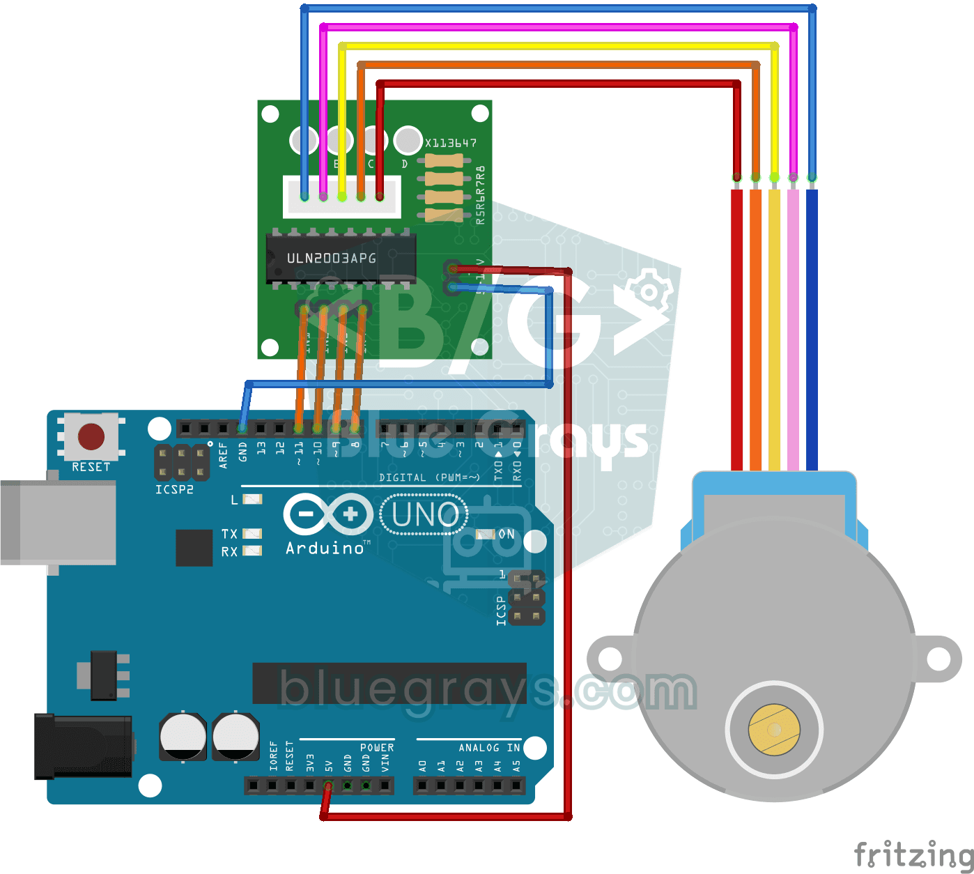
Using a Stepper Motor
A motor that turns step by step, exactly as far as you want, like the hand of a clock. Through a driver board, the Arduino turns a small stepper motor one full turn in one direction, waits a second, t
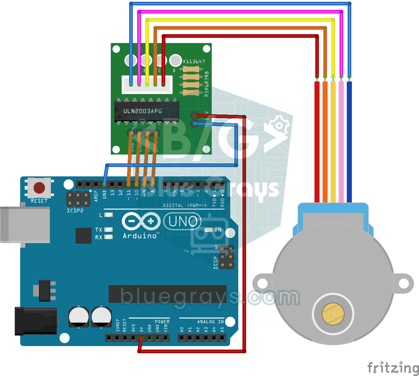
360-Degree Servo from a Stepper Motor
Teach an ordinary stepper motor to go to any angle you want, all the way around the circle. The Arduino works out how many steps each angle takes; the motor moves to 0, 90, 45, 180, 135 and 360 degree
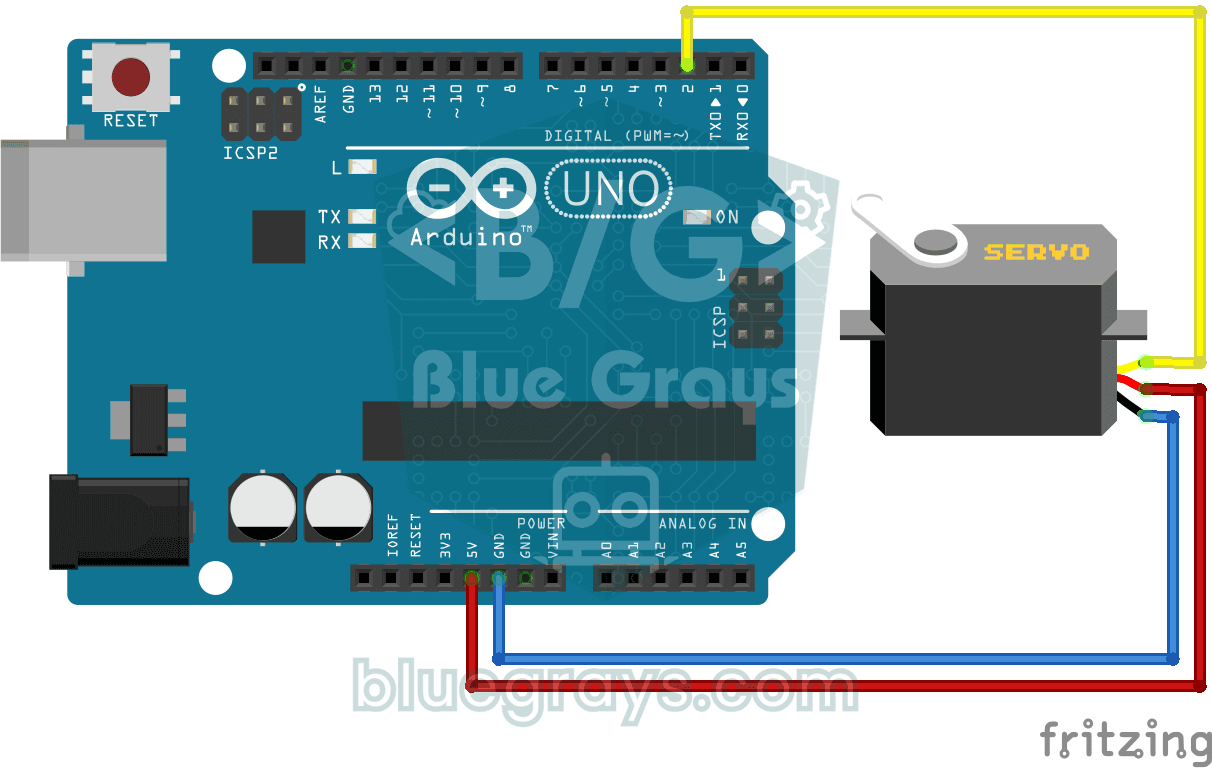
Using a Servo Motor
The arm of a small servo motor turns to three positions in turn: all the way to the start, right to the middle and all the way to the end, waiting two seconds at each stop. The Arduino tells the motor
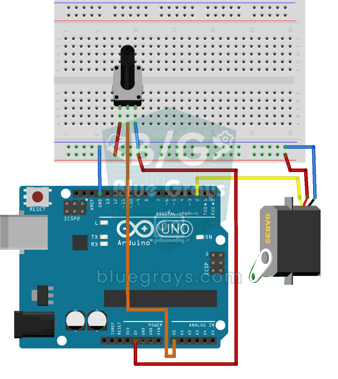
Servo Motor Operation with Potentiometer
As you turn the potentiometer knob, the servo motor's arm turns right along with it: one end of the knob means zero degrees, the other end means half a turn. The Arduino keeps reading the knob's posit
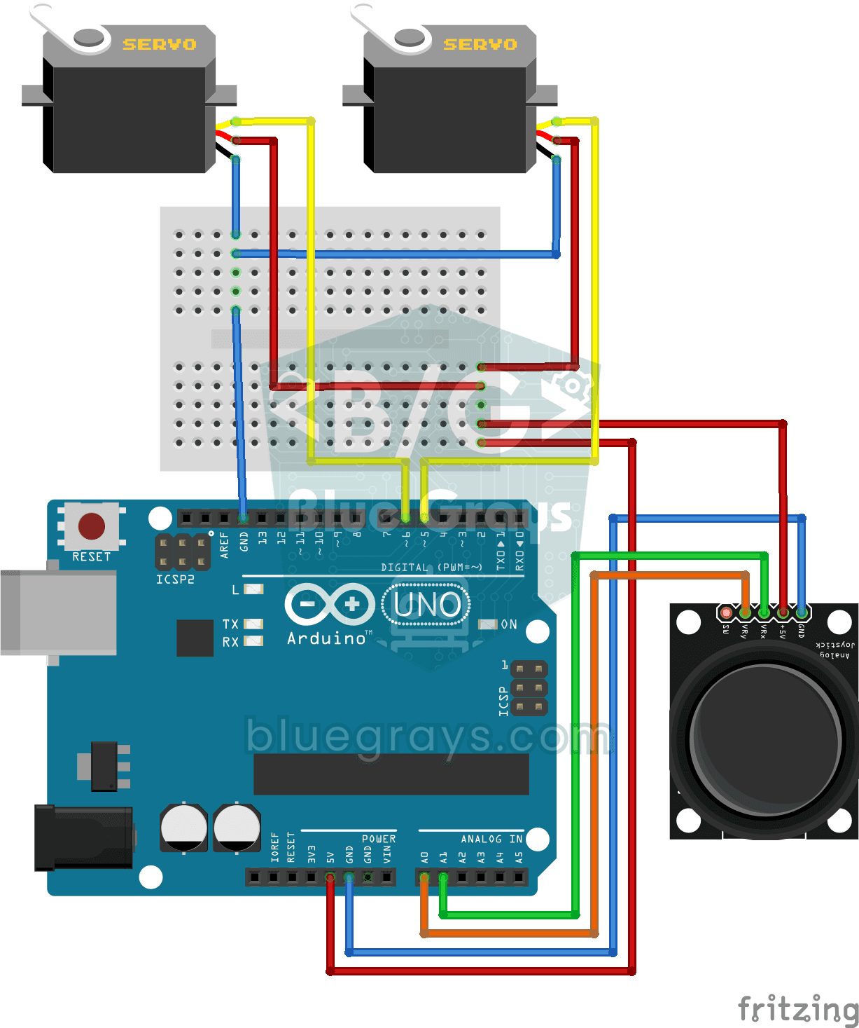
Servo Control with Joystick
Steer two motors with a joystick, just like turning a security camera. Push the stick left or right and the bottom servo motor slowly turns, push it up or down and the top servo tilts up and down; let

ESP32 Servo Motor (Potentiometer Control)
In this project, we control an SG90 servo motor using a potentiometer. We adjust the servo angle by mapping the analog value read from the potentiometer to the 0–180-degree range. The ESP32Servo library generates servo signals on suitable output-capable GPIO pins of the ESP32; this project uses GPIO 18. This is a fundamental control method for robotic arms, camera gimbals, and automatic door mechanisms.

Bluetooth Controlled Car with L298N
Turn your phone into a remote and drive your own robot car. The Arduino receives commands from a remote-control app on your phone through a Bluetooth module and spins the wheels with a motor driver; t

Obstacle Avoidance Robot
How about building a smart vehicle that finds its own way? The Obstacle Avoidance Robot constantly scans its surroundings thanks to the ultrasonic sensor in front of it. When it encounters an obstacle