
L9110S Arduino: Dual Motor Driver and PWM Speed Control
How do you wire an L9110S motor driver to Arduino? Pinout, direction and PWM speed control, the 800 mA limit, robot car and fan examples, plus Uno, ESP32 and Pico code.

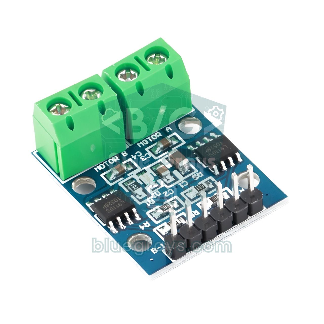
The L9110S is a fingertip-sized, very cheap dual-channel motor driver module that lets you control both the direction and the speed of two small DC motors at the same time. The L9110S and Arduino make one of the most practical combinations for battery-powered mini robot cars, small fans, toy boats and propeller projects. The module carries two L9110S chips, and each one can drive a motor with about 800 mA of continuous current per channel over a 2.5–12 V range.
An Arduino pin can't supply enough current to run a motor directly: an Uno pin gives 20–40 mA at most, while a small yellow geared motor draws many times that at start-up. To change a motor's direction you also have to reverse the direction of the current through it. In this article you'll learn the L9110S pinout, truth table, PWM speed control and current limit, and you'll write code for a robot car with an Arduino Uno, a potentiometer-controlled fan with an ESP32, and MicroPython on a Raspberry Pi Pico. In the last section we'll clarify when the L9110S can replace the L298N and when it can't.
What is the L9110S and how does it work?
Inside the L9110S is an H-bridge made of four switches. When the switches open and close in diagonal pairs, current flows through the motor in one direction or the other, and the motor turns forward or backward accordingly. Each H-bridge has two input pins (IA and IB) and two output pins (OA and OB). Give IA HIGH and IB LOW and the motor turns one way; swap them and it turns the other way. If you apply a PWM signal to one of these two inputs, the average voltage the motor sees changes, and that's how you set its speed. The chip also includes protection diodes against the reverse voltage spikes the motor generates when it stops or changes direction, so you don't need to add an external diode. The module has no separate logic supply or 5 V regulator: the voltage you give the VCC pin powers both the chips and the motors.
| Feature | Value |
|---|---|
| Driver chip | 2 × L9110S (one per motor) |
| Channels | 2 DC motors or 1 small bipolar stepper motor |
| Supply voltage (VCC) | 2.5–12 V |
| Continuous current | About 800 mA per channel |
| Peak current | About 1.5 A for short periods |
| Logic input | 3.3 V and 5 V compatible |
| Speed control | PWM on the input pins (no separate enable pin) |
| Protection | Built-in freewheeling diodes |
| Size | About 3 × 2.5 cm, a few grams |
L9110S pinout and truth table
| Pin | Function |
|---|---|
| B-IA | Input 1 of motor B (PWM allowed) |
| B-IB | Input 2 of motor B (PWM allowed) |
| GND | Common ground (battery negative and microcontroller GND) |
| VCC | Motor and chip supply, 2.5–12 V |
| A-IA | Input 1 of motor A (PWM allowed) |
| A-IB | Input 2 of motor A (PWM allowed) |
| MOTOR A / MOTOR B | Two-pole screw terminals where the motors connect |
| A-IA | A-IB | Motor A |
|---|---|---|
| HIGH | LOW | Turns forward |
| LOW | HIGH | Turns backward |
| LOW | LOW | Stops |
| HIGH | HIGH | Stops |
| PWM | LOW | Forward, speed set by duty cycle |
| LOW | PWM | Backward, speed set by duty cycle |
"Forward" and "backward" here are only labels; which way the motor actually turns depends on the order in which you connect its wires to the terminal. If a motor spins the wrong way, just swap its two wires instead of fiddling with the code. Since the module has no ENA/ENB pins like the L298N, you apply PWM to one of the two inputs for speed. If you're short on PWM pins you can hold one input at a constant HIGH and PWM the other, but then the logic is inverted: as the duty cycle rises the motor slows down, because the motor stops when both inputs are HIGH. That's why the cleanest method is to dedicate two PWM pins per motor.
L9110S wiring: Arduino Uno, ESP32 and Pico
| L9110S pin | Arduino Uno | ESP32 | Raspberry Pi Pico |
|---|---|---|---|
| A-IA | D5 | GPIO 25 | GP16 |
| A-IB | D6 | GPIO 26 | GP17 |
| B-IA | D9 | GPIO 32 | GP18 |
| B-IB | D10 | GPIO 33 | GP19 |
| VCC | Battery positive (e.g. 4×AA, 6 V) | Battery positive (e.g. 4×AA, 6 V) | Battery positive (e.g. 4×AA, 6 V) |
| GND | GND (shared with battery negative) | GND (shared with battery negative) | GND (shared with battery negative) |
| Potentiometer wiper (optional) | A0 | GPIO 34 | GP26 |
Choose a supply close to your motor's rated voltage. For yellow TT geared motors and N20 micro motors, 4 AA batteries (about 6 V) are an ideal start. Two 18650 Li-Ion cells in series give 7.4 V (8.4 V fully charged); 6 V motors can take this but they run hotter and wear faster, so limiting the top speed with PWM is a good idea. Soldering a 100 µF electrolytic capacitor across the module's VCC line close to the terminal, and a 100 nF ceramic capacitor across each motor's two terminals, greatly reduces motor noise reaching the microcontroller. To estimate battery life you can use the battery life calculator: a robot drawing 450 mA in total from 2000 mAh AA cells lasts roughly 2000 / 450 ≈ 4.4 hours; in practice it's a little shorter.
Step by step: a robot car with the L9110S (Arduino Uno)
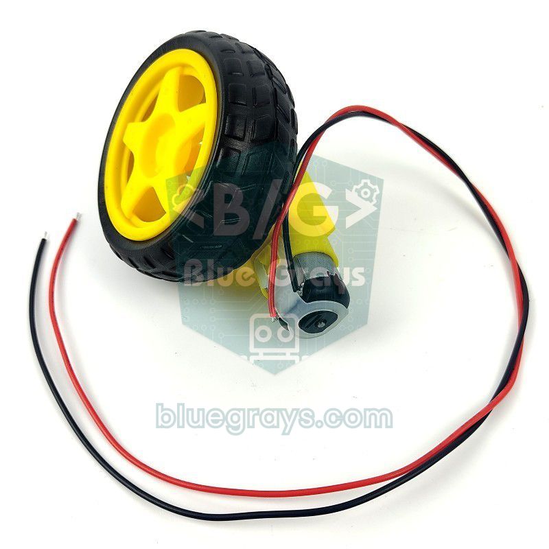
- Mount the two geared DC motors on the chassis; connect the left motor to the MOTOR A terminal and the right motor to MOTOR B.
- Connect the module's A-IA and A-IB pins to Uno pins D5 and D6, and B-IA and B-IB to D9 and D10; all four support PWM.
- Connect the positive end of the 4×AA battery holder to the module's VCC pin and the negative end to GND.
- Create the common ground by connecting the module's GND pin to the Uno's GND pin with a jumper wire.
- Power the Uno over USB and upload the code below; lift the wheels off the ground for the first test.
- If a motor turns the wrong way, swap that motor's two wires at the terminal.
1// L9110S ile iki motorlu robot araba / Two-motor robot car with L9110S
2const int A_IA = 5;   // Sol motor girişi 1 (PWM) / left motor input 1 (PWM)
3const int A_IB = 6;   // Sol motor girişi 2 (PWM) / left motor input 2 (PWM)
4const int B_IA = 9;   // Sağ motor girişi 1 (PWM) / right motor input 1 (PWM)
5const int B_IB = 10;  // Sağ motor girişi 2 (PWM) / right motor input 2 (PWM)
6
7// hız: -255 tam geri, 0 dur, 255 tam ileri / speed: -255 full reverse, 0 stop, 255 full forward
8void setMotor(int pinIA, int pinIB, int speed) {
9  speed = constrain(speed, -255, 255);
10  if (speed > 0) {
11    analogWrite(pinIA, speed);   // ileri / forward
12    analogWrite(pinIB, 0);
13  } else if (speed < 0) {
14    analogWrite(pinIA, 0);       // geri / reverse
15    analogWrite(pinIB, -speed);
16  } else {
17    analogWrite(pinIA, 0);       // dur / stop
18    analogWrite(pinIB, 0);
19  }
20}
21
22void drive(int left, int right) {
23  setMotor(A_IA, A_IB, left);
24  setMotor(B_IA, B_IB, right);
25}
26
27void setup() {
28  pinMode(A_IA, OUTPUT);
29  pinMode(A_IB, OUTPUT);
30  pinMode(B_IA, OUTPUT);
31  pinMode(B_IB, OUTPUT);
32  drive(0, 0);
33  delay(2000);                   // tekerlekleri kaldırmak için süre / time to lift the wheels
34}
35
36void loop() {
37  for (int s = 80; s <= 200; s += 5) {   // yumuşak kalkış / soft start
38    drive(s, s);
39    delay(30);
40  }
41  delay(1500);                   // 200 hızla ileri / forward at speed 200
42  drive(0, 0);
43  delay(500);
44  drive(-160, -160);             // geri / reverse
45  delay(1000);
46  drive(0, 0);
47  delay(500);
48  drive(-150, 150);              // yerinde sola dön / spin left in place
49  delay(600);
50  drive(150, -150);              // yerinde sağa dön / spin right in place
51  delay(600);
52  drive(0, 0);
53  delay(2000);
54}| Code piece | What it does |
|---|---|
| setMotor(pinIA, pinIB, speed) | Sends PWM to one input and 0 to the other depending on the sign of the speed; positive means forward, negative backward, 0 stop. |
| constrain(speed, -255, 255) | Clips values that exceed the analogWrite range. |
| drive(left, right) | Controls both motors together; equal values go straight, opposite signs spin the car in place. |
| for loop (80 → 200) | Soft start: reduces the sudden current spike and wheel slip. |
| drive(-150, 150) | The left motor turns backward and the right forward; the car spins left around its own axis. |
Speed control with PWM: duty cycle and average voltage
PWM applies an average voltage to the motor by switching the pin on and off hundreds of times per second. Thanks to its inertia, the motor perceives these fast pulses as an average. You can calculate the average voltage roughly with the formula V_avg = V_supply × duty / 255: with a 6 V supply, analogWrite(pin, 150) corresponds to about 6 × 150 / 255 ≈ 3.5 V. On the Arduino Uno, pins D5 and D6 produce about 980 Hz PWM and pins D9 and D10 about 490 Hz; a slight whine from the motor at these frequencies is normal. On the ESP32 and Pico you can choose the frequency yourself; around 1 kHz is a safe start for the L9110S. At very high frequencies the chip produces more heat with every switching, while at very low frequencies the motor turns with a judder. For more detail, take a look at the What Is PWM article.
Current limit: which motors can the L9110S drive?
The L9110S's most important limit is about 800 mA of continuous current per channel. The value to watch isn't the current the motor draws with no load but its stall current. When the motor starts, or when a wheel hits an obstacle and stops, only the winding resistance limits the current and the motor draws its maximum. You can estimate it roughly with Ohm's law: if the winding resistance you measure with a multimeter is 5 Ω and the supply is 6 V, the stall current is about 6 / 5 = 1.2 A. This is no problem during a brief start-up, but if the car pushes against a wall and waits for seconds with the wheels unable to turn, the chip heats up quickly. Since the module has no heatsink, it's best not to keep continuous loads above 500 mA per channel for long.
| Motor | Typical current | For the L9110S |
|---|---|---|
| N20 micro geared motor (6 V) | 30–100 mA no load | Very suitable |
| TT yellow geared motor (3–6 V) | 150–250 mA no load, about 1 A at stall | Suitable; avoid long stalls |
| 130-type DC motor + propeller | 200–500 mA | Suitable (mini fan) |
| 5 V brushless computer fan | 100–250 mA | Suitable in one direction only |
| 12 V metal geared motor (25GA/37GA) | 2–5 A at stall | Not suitable, needs a stronger driver |
| RS-550 / 775 motor | A few amps to tens of amps | Definitely not suitable |
L9110S with ESP32: fan speed and direction with a potentiometer
The ESP32's pins work at 3.3 V and the L9110S inputs read this level without trouble; you don't need a level shifter. In the example below we connect a small 130 motor with a propeller to the MOTOR A terminal. With a potentiometer whose outer pins go to 3V3 and GND and whose wiper goes to GPIO 34, the fan stops when it's in the middle; turn it one way and it blows faster and faster, turn it the other way and it sucks in the reverse direction. The small dead zone in the middle stops the potentiometer's jittery readings from constantly nudging the motor back and forth. The code separates the LEDC difference between ESP32 Arduino core 2.x and 3.x with #if; if you want to use channel B too, you can add GPIO 32 and 33 the same way.
1// ESP32 + L9110S: potansiyometre ile fan hızı ve yönü / fan speed and direction with a potentiometer
2const int FAN_IA = 25;      // Motor A girişi 1 / Motor A input 1
3const int FAN_IB = 26;      // Motor A girişi 2 / Motor A input 2
4const int POT_PIN = 34;     // Potansiyometre orta ucu (ADC1) / potentiometer wiper (ADC1)
5const int PWM_FREQ = 1000;  // PWM frekansı (Hz) / PWM frequency (Hz)
6const int PWM_RES = 8;      // 8 bit: 0-255 / 8 bit: 0-255
7const int DEAD_ZONE = 40;   // ortadaki ölü bölge / dead zone around the middle
8
9void pwmBegin(int pin, int channel) {
10#if ESP_ARDUINO_VERSION_MAJOR >= 3
11  (void)channel;                          // 3.x kanalı kendisi seçer / 3.x picks the channel itself
12  ledcAttach(pin, PWM_FREQ, PWM_RES);
13#else
14  ledcSetup(channel, PWM_FREQ, PWM_RES);  // 2.x: önce kanal ayarı / 2.x: set up the channel first
15  ledcAttachPin(pin, channel);
16#endif
17}
18
19void pwmSet(int pin, int channel, int duty) {
20#if ESP_ARDUINO_VERSION_MAJOR >= 3
21  (void)channel;
22  ledcWrite(pin, duty);                   // 3.x: pin numarasıyla / 3.x: by pin number
23#else
24  (void)pin;
25  ledcWrite(channel, duty);               // 2.x: kanal numarasıyla / 2.x: by channel number
26#endif
27}
28
29void setFan(int speed) {
30  speed = constrain(speed, -255, 255);
31  if (speed >= 0) {
32    pwmSet(FAN_IA, 0, speed);   // üfle / blow
33    pwmSet(FAN_IB, 1, 0);
34  } else {
35    pwmSet(FAN_IA, 0, 0);       // ters yönde em / suck in reverse
36    pwmSet(FAN_IB, 1, -speed);
37  }
38}
39
40void setup() {
41  Serial.begin(115200);
42  analogReadResolution(12);     // 0-4095
43  pwmBegin(FAN_IA, 0);
44  pwmBegin(FAN_IB, 1);
45  setFan(0);
46}
47
48void loop() {
49  int raw = analogRead(POT_PIN);
50  int speed = map(raw, 0, 4095, -255, 255);
51  if (abs(speed) < DEAD_ZONE) speed = 0;  // ortada dur / stop in the middle
52  setFan(speed);
53  Serial.printf("ADC: %d  Hiz/Speed: %d\n", raw, speed);
54  delay(50);
55}
Raspberry Pi Pico and MicroPython with the L9110S
Every GPIO pin on the Pico can produce hardware PWM, so you have plenty of freedom in choosing pins. In the example the left motor is on GP16 and GP17 and the right motor on GP18 and GP19. The code defines each motor as a class and takes the speed as a percentage (-100 to 100), so you don't have to deal with duty_u16's 0–65535 range. Power the Pico over USB and the motors from the battery pack connected to the module's VCC, and join the two GNDs. When you stop the program with Ctrl+C in Thonny, the KeyboardInterrupt block safely stops the motors; without it the PWM hardware keeps running and your car could drive off the table.
1from machine import Pin, PWM
2import time
3
4class Motor:
5    def __init__(self, pin_ia, pin_ib, freq=1000):
6        self.ia = PWM(Pin(pin_ia))       # IA girişi / IA input
7        self.ib = PWM(Pin(pin_ib))       # IB girişi / IB input
8        self.ia.freq(freq)
9        self.ib.freq(freq)
10        self.stop()
11
12    def speed(self, percent):            # -100 geri ... 100 ileri / -100 reverse ... 100 forward
13        percent = max(-100, min(100, percent))
14        duty = int(abs(percent) * 65535 // 100)
15        if percent > 0:
16            self.ia.duty_u16(duty)
17            self.ib.duty_u16(0)
18        elif percent < 0:
19            self.ia.duty_u16(0)
20            self.ib.duty_u16(duty)
21        else:
22            self.stop()
23
24    def stop(self):
25        self.ia.duty_u16(0)
26        self.ib.duty_u16(0)
27
28left = Motor(16, 17)    # A-IA = GP16, A-IB = GP17
29right = Motor(18, 19)   # B-IA = GP18, B-IB = GP19
30
31def drive(l, r, ms):
32    left.speed(l)
33    right.speed(r)
34    time.sleep_ms(ms)
35
36try:
37    while True:
38        for s in range(30, 81, 5):       # yumuşak kalkış / soft start
39            drive(s, s, 40)
40        drive(80, 80, 1500)              # ileri / forward
41        drive(0, 0, 500)
42        drive(-60, -60, 1000)            # geri / reverse
43        drive(0, 0, 500)
44        drive(-60, 60, 600)              # yerinde sola dön / spin left in place
45        drive(0, 0, 2000)
46except KeyboardInterrupt:
47    left.stop()                          # Ctrl+C ile güvenli dur / safe stop on Ctrl+C
48    right.stop()
L9110S or L298N? Which should you use?
| Feature | L9110S module | L298N module |
|---|---|---|
| Motor voltage | 2.5–12 V | About 5–35 V |
| Current per channel | About 800 mA continuous | About 2 A continuous |
| Voltage drop across the driver | Low | About 2 V or more |
| Speed control | PWM on the IA/IB pins | PWM on the ENA/ENB pins |
| Control pins needed | 4 | 6 (4 with jumpers) |
| Built-in 5 V regulator | None | Yes (with supply up to 12 V) |
| Size and weight | Very small, a few grams | Large, with a heatsink |
| 3.3 V logic | Compatible | Usually works |
In short, if your motors are under 12 V and none of them goes much above 1 A even at stall, the L9110S is the better choice: it's smaller, lighter, and doesn't waste the roughly 2 V lost in the L298N's bipolar transistors. This difference is very noticeable in battery-powered projects: with a 6 V battery pack the L298N leaves around 4 V for the motor, while the L9110S passes most of the supply to the motor and your car visibly goes faster. On the other hand, for 12 V metal geared motors, heavy chassis, continuous loads above 1 A or supplies above 12 V, you need the L298N or more modern MOSFET drivers. For a detailed comparison with alternatives such as the TB6612FNG, see the motor driver comparison article.
L9110S project ideas
- Bluetooth-controlled mini car: with an HC-05 module, call the drive() function based on the letters coming from your phone.
- Obstacle-avoiding robot: add an HC-SR04 up front and build a robot that backs off and turns when an obstacle is closer than 20 cm; details are in the obstacle-avoiding robot article.
- Line-following robot: follow a black line with two TCRT5000 sensors; N20 motors and the L9110S make a light and agile robot.
- Temperature-controlled fan: raise the fan speed gradually with PWM according to the measured temperature; you'll find the logic in the Arduino fan control article.
- Tank driving with a joystick: turn the joystick X and Y axes into left and right motor speeds.
- Wi-Fi-controlled car: send direction and speed commands from buttons on a web page served by an ESP32.
- Mini crane or curtain opener: wind a string with a geared motor; stop the motor at the end points with a limit switch.
Common mistakes and how to fix them
| Symptom | Likely cause | Fix |
|---|---|---|
| The motor doesn't turn at all | No common GND, or no supply reaching VCC | Connect the module GND to the board GND and measure VCC with a multimeter |
| The motor doesn't turn at low speed, it only hums | The duty value is below the motor's starting threshold | Raise the minimum speed to around 70–100 |
| The Arduino resets when the motor starts | The motors are powered from the same 5V rail as the board | Use a separate battery for the motors and add a 100 µF capacitor to VCC |
| It turns in one direction but not the other | One input is on a non-PWM pin or a wire isn't making contact | Connect all four inputs to PWM pins and check the jumpers |
| The chip gets very hot | Motor current exceeds the 800 mA limit, or the motor is stalled | Use a smaller motor, avoid stalls, or switch to an L298N |
| Speed control works backwards | One input is HIGH and the other is PWM | Make the fixed input LOW, or subtract the duty value from 255 |
| The motor spins briefly when the ESP32 boots | The chosen pin outputs a signal at start-up | Use pins that stay quiet at boot, such as GPIO 25, 26, 32 and 33 |
The L9110S is a light, cheap and efficient driver for battery-powered projects with small motors; if you know its limits and match it with the right motor, it will run trouble-free for a long time. When you move on to bigger motors, you can keep using the same direction and PWM logic with the L298N. In the BlueGrays app you'll find step-by-step circuit diagrams and code for projects such as a Bluetooth-controlled car, an obstacle-avoiding robot and potentiometer PWM control, and you can easily adapt the L9110S wiring here to them. The building an Arduino robot car guide will also help you choose the chassis, wheels and battery.
Frequently asked questions
How many amps can the L9110S handle?
The L9110S can supply about 800 mA of continuous current per channel, with a short-term peak of around 1.5 A. Because the module has two chips, it drives two motors separately, each with this limit. For a long life, it's a good rule to keep the continuous current per motor below 500–600 mA.
Can the L9110S drive a 12 V motor?
The module's maximum supply voltage is 12 V, so a small 12 V motor can theoretically be driven. However, most 12 V motors draw well over 1 A at stall, and a chip working at its limit gets hot. For 12 V motors an L298N or a MOSFET-based driver is a safer choice.
Does the L9110S work with the ESP32 and 3.3 V?
Yes. The L9110S input pins read a 3.3 V logic level as HIGH, so you can connect it directly to the ESP32, Raspberry Pi Pico and other 3.3 V boards. You just need to supply the motor power separately to VCC and join the GNDs.
Is the L9110S or the L298N better?
For battery-powered projects with small motors, the L9110S is better; it's smaller and lighter, and it doesn't lose about 2 V like the L298N. If the motor current exceeds 1 A or you need a supply above 12 V, choose the L298N.
Can the L9110S drive a stepper motor?
Yes, the two H-bridges on the module can drive the two coils of a small bipolar (4-wire) stepper motor, and the Arduino Stepper library works with this wiring. The coil current must not exceed 800 mA. For 5-wire unipolar motors such as the 28BYJ-48, a ULN2003 board is more suitable.
Why does the L9110S get so hot?
The most common cause of heating is the motor drawing current close to the chip's limit; motors with jammed wheels or heavy loads especially approach their stall current. A supply voltage higher than the motor's rated voltage also raises the current. Use a smaller motor, limit the top speed with PWM, or move to a more powerful driver.
Projects to build after reading this
See all projects
Bluetooth Controlled Car with L298N
Turn your phone into a remote and drive your own robot car. The Arduino receives commands from a remote-control app on your phone through a Bluetooth module and spins the wheels with a motor driver…

Obstacle Avoidance Robot
How about building a smart vehicle that finds its own way? The Obstacle Avoidance Robot constantly scans its surroundings thanks to the ultrasonic sensor in front of it.

ESP32 LED Brightness Control with a Potentiometer (Analog → PWM)
In this project, we control the brightness of an LED analogically using a potentiometer. The ESP32's ADC pin reads the 0-3.3V voltage from the potentiometer, and this value is then converted into a PWM (Pulse Width Modulation) signal and sent to the LED. As a result, as you turn the potentiometer, the LED gradually brightens and dims. With Arduino Core 3.0+, analogWrite() can be used directly; on the ESP32-S2/S3, the ADC resolution is fixed at 12-bit.

ESP32 LED Fade with PWM
Smoothly changing the brightness of the LED from 0 to max, from max to 0. We control PWM with analogWrite() as in Arduino - the same syntax as ESP32 Arduino Core 3.0+ works without problems. Pin definition + pinMode + analogWrite is enough.
Raspberry Pi Pico PWM LED Fade (Breathing Effect)
The LED doesn't just blink anymore, it breathes! With the Raspberry Pi Pico's PWM (Pulse Width Modulation), the LED's brightness slowly rises and then slowly fades, a calm "breathing" effect like a sleeping laptop's light. You'll learn the machine.PWM class, the 16-bit brightness value from 0–65535 with duty_u16() and the PWM frequency.
Servo Control with Joystick
Steer two motors with a joystick, just like turning a security camera. Push the stick left or right and the bottom servo motor slowly turns, push it up or down and the top servo tilts up and down…
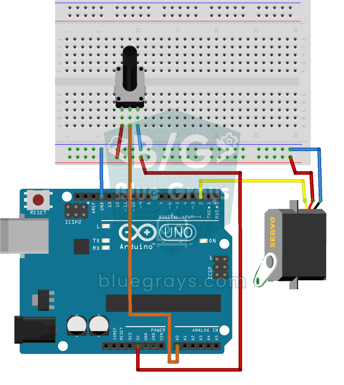
Servo Motor Operation with Potentiometer
As you turn the potentiometer knob, the servo motor's arm turns right along with it: one end of the knob means zero degrees, the other end means half a turn.
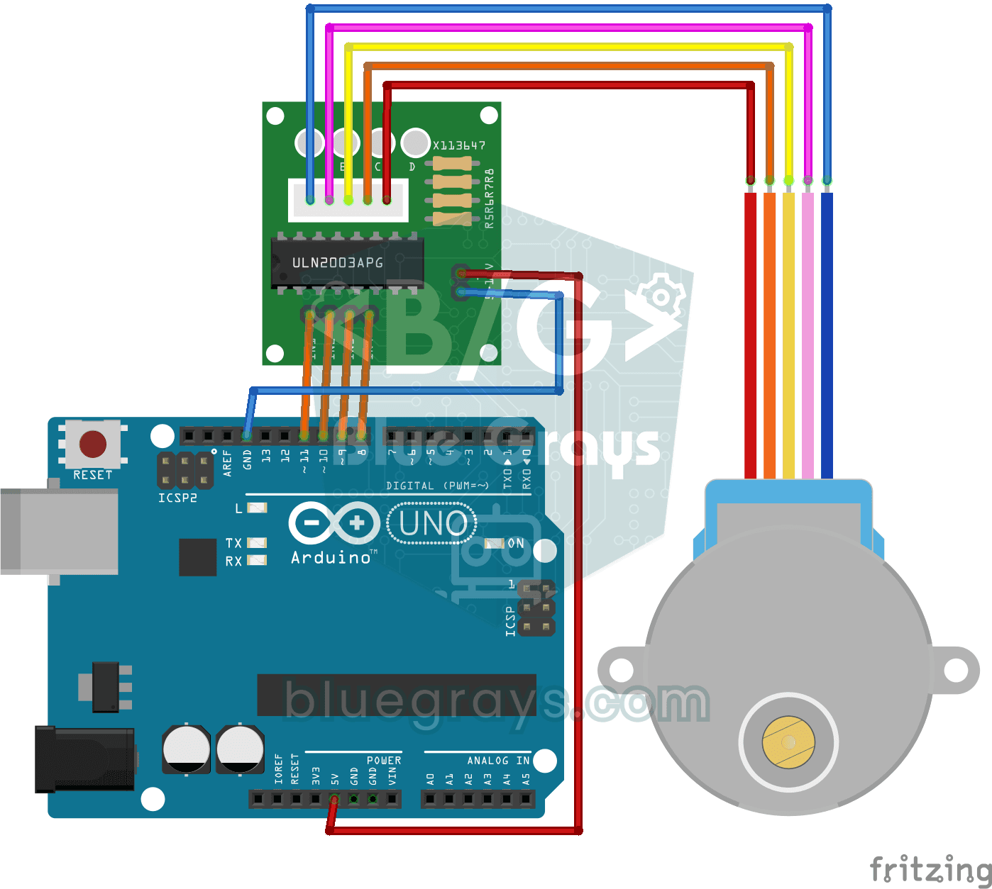
Using a Stepper Motor
A motor that turns step by step, exactly as far as you want, like the hand of a clock.