
L293D Motor Shield Arduino: AFMotor, 4 DC Motors, Stepper, Servo
How to use the L293D motor shield: AFMotor library, PWR jumper, free pins, 4WD car code, steppers, servos, the 0.6 A limit and fixes for motors not turning.
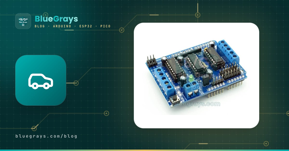
The L293D motor shield is a motor driver board that plugs straight on top of an Arduino Uno and lets you drive 4 DC motors, 2 stepper motors and 2 servos from a single board. Its two L293D chips supply the current the motors need, reverse their direction and set their speed with PWM, so you can control every motor of a four-wheel robot car without a single jumper wire. Almost every board on the market is a copy of Adafruit's old Motor Shield V1 design and is programmed with the same library: AFMotor.
In this guide you'll learn what's on the shield, which Arduino pins it uses and which ones stay free for sensors, how the confusing PWR jumper works in three different power setups, the commands of the AFMotor library and the complete code for a four-wheel robot car you drive from your phone. In the last sections we cover the 0.6 A current limit, why the chip gets hot, how it compares with the L298N and every known cause of "my motors won't turn" in a single table.
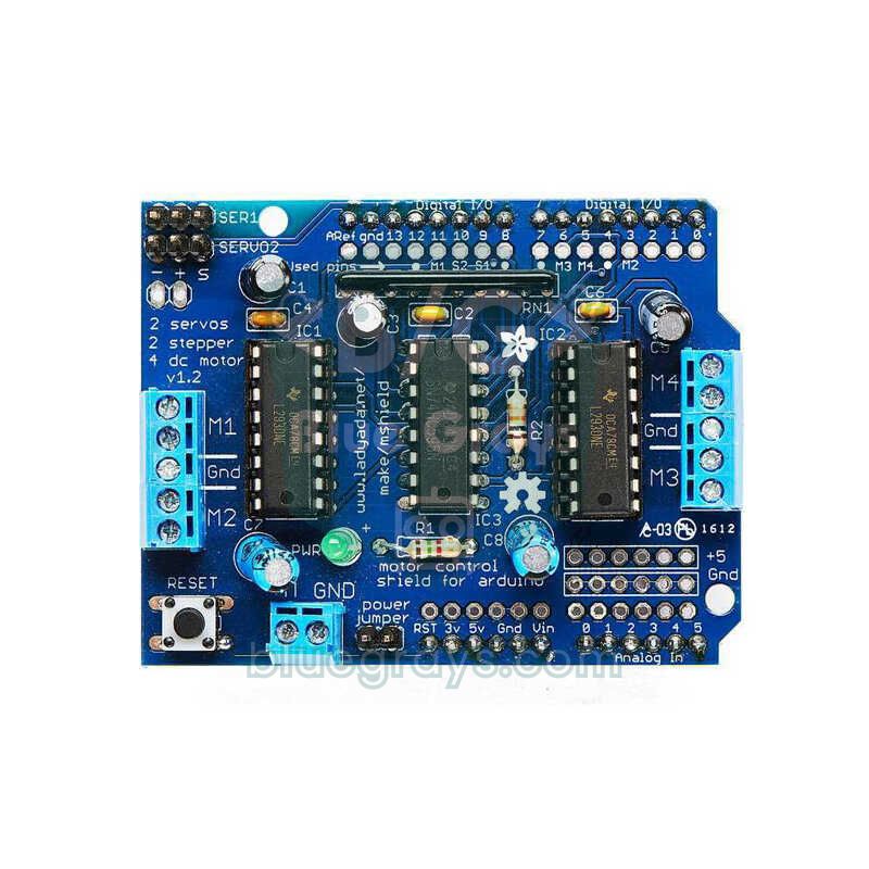
What is the L293D motor shield and how does it work?
To spin a DC motor in both directions you need a four-switch circuit called an H-bridge; we explain the idea in detail in L298N DC Motor Control. The L293D chip contains two H-bridges, and since the shield carries two of these chips you get four motor channels in total. The "D" in the name means the protection diodes that absorb the reverse voltage spikes a motor produces when it switches off are built into the chip. The L293D also shuts its outputs down by itself when it overheats.
The real trick of the shield is the 74HC595 shift register in the middle. Each of the four motors needs two signals for direction and one for speed, which adds up to 12 Arduino pins. The shield sends the eight direction signals serially to the 74HC595 and spends only 4 pins on them (D4, D7, D8, D12), plus 4 PWM pins for speed (D3, D5, D6, D11). This design saves pins, but there's a price: you can't drive the motors directly with digitalWrite; you need a library that shifts the direction bits into the register. That library is AFMotor.
| Feature | Value |
|---|---|
| Driver chips | 2 × L293D (4 H-bridges in total) |
| Direction control | 74HC595 shift register (D4, D7, D8, D12) |
| Motor supply voltage | 4.5–25 V (external power terminal) |
| Current per channel | 0.6 A continuous, 1.2 A very short peak |
| Speed control | 8-bit PWM, setSpeed(0–255) |
| Motors it can drive | 4 DC motors, 2 steppers or 2 DC + 1 stepper |
| Servos | 2, powered from the Arduino's 5 V rail (D9 and D10) |
| Protection | Built-in diodes, thermal shutdown |
| Compatible boards | Arduino Uno R3 and Mega 2560 (Uno R4 and Leonardo not supported) |
What's on the board? Terminals, headers and jumper
| Part | What it does |
|---|---|
| M1 and M2 terminal block (left) | DC motors 1 and 2; the GND screw in the middle is for the common wire of a unipolar stepper |
| M3 and M4 terminal block (right) | DC motors 3 and 4, or stepper port 2 |
| EXT_PWR (+M and GND) | Motor power input: battery pack or adapter |
| PWR jumper | When fitted, connects the motor supply to the Arduino's Vin rail |
| SER1 and SERVO_2 | Two servo headers (−, +, S); D10 and D9 |
| PWR LED | Shows whether motor power is present; if it's off, the motors won't turn |
| RESET button | A copy of the Arduino's reset button on top of the shield |
| A0–A5 row | Free analog pins; most boards also have +5V and GND rows next to them |
Which pins does the shield use and which stay free?
| Arduino pin | Job on the shield | When is it busy? |
|---|---|---|
| D3 | M2 speed (PWM, Timer2) | When M2 or stepper 1 is used |
| D4 | 74HC595 clock (CLK) | When any DC or stepper motor is used |
| D5 | M4 speed (PWM, Timer0) | When M4 or stepper 2 is used |
| D6 | M3 speed (PWM, Timer0) | When M3 or stepper 2 is used |
| D7 | 74HC595 output enable (EN) | When any motor is used |
| D8 | 74HC595 data input (DATA) | When any motor is used |
| D9 | SERVO_2 signal (Timer1) | Only when that servo is used |
| D10 | SER1 signal (Timer1) | Only when that servo is used |
| D11 | M1 speed (PWM, Timer2) | When M1 or stepper 1 is used |
| D12 | 74HC595 latch (LATCH) | When any motor is used |
| D0, D1 | Not used (USB serial line) | While uploading and while the Serial Monitor is open |
| D2 | Not used; there's a small solder pad on the board | Never |
| D13 | Not used, but not broken out on top of the shield | Never |
| A0–A5 (D14–D19) | Not used; broken out in a row along the edge | Never |
The six free analog pins are more than enough for sensors, because the Uno's A0–A5 also work as digital pins 14–19 when needed. A practical layout could be: an HC-SR04 distance sensor or a Bluetooth module via SoftwareSerial on A0 and A1, line-tracking or obstacle sensors on A2 and A3, and the I2C bus (OLED, LCD, MPU6050) on A4 and A5. For a wheel encoder or a button that uses attachInterrupt(), D2 is the only free pin; the Uno's other interrupt pin, D3, is M2's speed pin. If you don't use servos, D9 and D10 are free too. You can see your board's layout in the Pinout tool and what each pin can do in Arduino Uno Pinout.
Power and the PWR jumper: three correct ways to wire it
The two-screw EXT_PWR terminal on the bottom edge of the board is the power input for the motors; the positive side is usually marked "+M" or "+" and the negative side "GND". The PWR jumper right next to it connects this motor line to the Arduino's Vin pin. With the jumper fitted, both boards run from one source: the voltage you feed into EXT_PWR also powers the Arduino through Vin, or an adapter plugged into the Arduino's DC jack also powers the motors. With the jumper removed, the two lines are completely separate. The PWR LED on the board only lights up when motor power is present; it's the first thing to check before you start troubleshooting motors.
| Setup | Arduino power | Motor power | PWR jumper |
|---|---|---|---|
| Single source (7–12 V battery or adapter) | Same source, through Vin | EXT_PWR or the Arduino's DC jack | Fitted |
| Arduino on USB, motors on batteries | USB cable | EXT_PWR | Removed |
| Two separate sources (the safest) | DC jack or USB | EXT_PWR | Removed |
The most common choice for robot cars is a single source: you connect a pack of two 18650 cells to EXT_PWR, fit the jumper, and both the Arduino and the motors run from the same battery. It's simple, but when the motors draw a lot of current on start-up the battery voltage can dip for a moment and the Arduino may reset. If that happens, removing the jumper and powering the Arduino from a separate source (a power bank, USB or a 9 V adapter) fixes it for good. On the bench, the second setup is the most practical: the Arduino stays connected to your computer, the motors run from batteries and the jumper is removed.
Which battery should you choose? Depending on the current, the L293D's output transistors swallow roughly 1.5–2.6 V, so the motor sees that much less than the battery voltage. For the yellow 3–6 V TT motors in robot kits, two 18650 lithium cells (7.4 V nominal, 8.4 V fully charged) are ideal: the motors get about 5.5–6 V, and with the jumper fitted the Arduino's regulator is comfortable too. Four AA cells (6 V) leave only about 4 V for the motors and aren't enough to power the Arduino through Vin. A 9 V PP3 battery can't deliver more than a few hundred milliamps; the motors either won't turn at all or the battery dies within minutes. You can estimate runtime with the battery life calculator and read about all the power options in How to Power Arduino with a Battery.
Installing the AFMotor library
- Open the Library Manager in the Arduino IDE (Tools > Manage Libraries or Ctrl+Shift+I).
- Type Adafruit Motor Shield in the search box. Two results appear: Adafruit Motor Shield library, whose description says "V1 firmware", and Adafruit Motor Shield V2 Library.
- For the L293D shield, install the V1 one. The V2 library is for a completely different board that talks over I2C and uses TB6612 chips.
- Add the line #include <AFMotor.h> at the top of your sketch.
- If you like, open File > Examples > Adafruit Motor Shield library > MotorTest and test the board with a motor on M1.
First sketch: running a DC motor forward, backward and at different speeds
Screw the motor's two wires into the two outer screws of the M1 terminal and leave the GND screw in the middle empty. Connect the battery pack to EXT_PWR, plug the Arduino into your computer over USB and remove the PWR jumper (the second setup above). If the PWR LED is on, upload the code below: the motor first speeds up and slows down gently, then runs backward for two seconds and stops.
1#include <AFMotor.h>                  // Adafruit Motor Shield V1 kütüphanesi / library
2
3AF_DCMotor motor(1);                  // M1 klemensi / M1 terminal
4
5void setup() {
6  Serial.begin(9600);
7  Serial.println(F("L293D motor testi / motor test"));
8  motor.setSpeed(200);                // 0–255; bunu unutursan motor dönmez / skip this and the motor won't turn
9  motor.run(RELEASE);                 // başlangıçta dur / start stopped
10}
11
12void loop() {
13  motor.run(FORWARD);                 // ileri / forward
14  for (int s = 60; s <= 255; s++) {   // yavaşça hızlan / ramp up
15    motor.setSpeed(s);
16    delay(10);
17  }
18  for (int s = 255; s >= 60; s--) {   // yavaşça yavaşla / ramp down
19    motor.setSpeed(s);
20    delay(10);
21  }
22  motor.run(RELEASE);                 // dur / stop
23  delay(500);
24
25  motor.setSpeed(180);
26  motor.run(BACKWARD);                // geri / backward
27  delay(2000);
28  motor.run(RELEASE);
29  delay(1000);
30}| Command | What it does |
|---|---|
| AF_DCMotor motor(1); | Creates the motor on the M1 terminal; takes a number from 1 to 4 |
| AF_DCMotor motor(1, MOTOR12_64KHZ); | Also selects the PWM frequency for M1 and M2 |
| motor.setSpeed(200); | Sets the speed from 0 to 255 (0 stops, 255 is full speed) |
| motor.run(FORWARD); | Runs forward |
| motor.run(BACKWARD); | Runs backward |
| motor.run(RELEASE); | Stops driving the motor; the motor stops |
| motor.run(BRAKE); | Defined in the library, but does nothing in V1 |
Speed is set by switching the motor's power on and off thousands of times per second; the details are in What Is PWM?. Because M1 and M2 use Timer2, you can choose their frequency: MOTOR12_64KHZ, MOTOR12_8KHZ (the default), MOTOR12_2KHZ and MOTOR12_1KHZ. 64 kHz makes the motor's whine inaudible, but the L293D runs hotter at that rate. M3 and M4, on the other hand, are tied to Timer0; since that timer also runs millis() and delay(), the library leaves its frequency alone and these two channels always run at about 1 kHz.
Four-wheel (4WD) robot car code
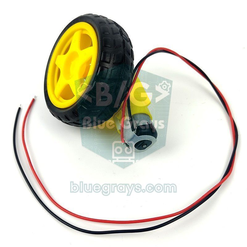
The favourite use of the L293D motor shield is a four-wheel robot car, because each of the four motors gets its own terminal and there's no wiring mess. These cars have no steering; they turn like a tank: if the two left wheels spin one way and the two right wheels the other, the car turns on the spot. That's why the code controls the motors not one by one but as two groups, the left side and the right side. For phone control we connect an HC-05 Bluetooth module to the free A0 and A1 pins with SoftwareSerial; the module is covered in detail in HC-05 Bluetooth Module.
| Part | Connection |
|---|---|
| Front left motor | M1 |
| Rear left motor | M2 |
| Rear right motor | M3 |
| Front right motor | M4 |
| HC-05 TXD | A0 (SoftwareSerial RX) |
| HC-05 RXD | A1, through a 1 kΩ + 2 kΩ voltage divider (5 V → 3.3 V) |
| HC-05 VCC and GND | The +5V and GND row on the shield |
| 2 × 18650 cells (7.4 V) | EXT_PWR (+M and GND), PWR jumper fitted |
1#include <AFMotor.h>
2#include <SoftwareSerial.h>
3
4AF_DCMotor frontLeft(1);              // M1: sol ön / front left
5AF_DCMotor rearLeft(2);               // M2: sol arka / rear left
6AF_DCMotor rearRight(3);              // M3: sağ arka / rear right
7AF_DCMotor frontRight(4);             // M4: sağ ön / front right
8
9SoftwareSerial bt(A0, A1);            // RX = A0 (HC-05 TXD), TX = A1 (HC-05 RXD, bölücüyle / via a divider)
10
11int speed = 200;                      // 0–255 arası sürüş hızı / driving speed 0–255
12
13void setSide(AF_DCMotor &a, AF_DCMotor &b, int value) {   // -255 … 255
14  uint8_t dir = value > 0 ? FORWARD : (value < 0 ? BACKWARD : RELEASE);
15  uint8_t pwm = constrain(abs(value), 0, 255);
16  a.setSpeed(pwm);
17  b.setSpeed(pwm);
18  a.run(dir);
19  b.run(dir);
20}
21
22void drive(int left, int right) {     // sol ve sağ taraf / left and right side
23  setSide(frontLeft, rearLeft, left);
24  setSide(frontRight, rearRight, right);
25}
26
27void setup() {
28  Serial.begin(9600);                 // hata ayıklama / debugging
29  bt.begin(9600);                     // HC-05 varsayılan hızı / default baud rate
30  drive(0, 0);
31}
32
33void loop() {
34  if (!bt.available()) return;
35  char c = bt.read();
36  Serial.println(c);
37
38  switch (c) {
39    case 'F': drive(speed, speed);        break;   // ileri / forward
40    case 'B': drive(-speed, -speed);      break;   // geri / backward
41    case 'L': drive(-speed, speed);       break;   // yerinde sola / spin left
42    case 'R': drive(speed, -speed);       break;   // yerinde sağa / spin right
43    case 'G': drive(speed / 3, speed);    break;   // ileri-sola kavis / curve forward-left
44    case 'I': drive(speed, speed / 3);    break;   // ileri-sağa kavis / curve forward-right
45    case 'S': drive(0, 0);                break;   // dur / stop
46    case 'q': speed = 255;                break;   // tam hız / full speed
47    default:
48      if (c >= '0' && c <= '9') speed = map(c - '0', 0, 9, 90, 240);   // hız kademesi / speed step
49  }
50}
The heart of the code is the drive(left, right) function: it takes a value from -255 to 255 for each side, where positive means forward, negative means backward and zero means stop. setSide() gives both motors on one side the same speed and direction. The commands are the single letters sent by "Arduino Bluetooth RC Car" style apps from the app stores: F forward, B backward, L and R spin on the spot, G and I curve, S stop. The speed slider in the app sends a digit from 0 to 9; the code turns it into a PWM value between 90 and 240, and because the lower limit is 90, the motors can still start on the lowest setting. If one wheel spins the wrong way, don't change the code; swap that motor's two wires in its terminal. For the chassis assembly and a two-motor version, see How to Make an Arduino Robot Car.
Driving stepper motors: 28BYJ-48 and NEMA 17
The shield can drive two steppers at once: stepper port 1 uses the M1 and M2 terminals and port 2 uses M3 and M4. With a bipolar motor (4 wires, like a NEMA 17) you connect one coil to M1 and the other coil to M2. With a unipolar motor (5 or 6 wires) the two coils also go to M1 and M2, and the common wire goes to the GND screw in the middle of the terminal block. For the popular 28BYJ-48, the wiring is: blue and yellow wires to M1, pink and orange wires to M2, and the red common wire to GND. Using this motor with the ULN2003 board is covered in What Is a Stepper Motor?.
| Step style | How it works | When to use it |
|---|---|---|
| SINGLE | One coil is energised at a time | Lowest current, lowest torque |
| DOUBLE | Two coils are energised together | Higher torque; the most common choice |
| INTERLEAVE | Alternates single and double coils (half-stepping) | Twice the resolution, smoother rotation |
| MICROSTEP | Coil currents change gradually with PWM; each full step is split into 16 | Slow and quiet rotation; torque drops |
The 28BYJ-48 is a 5 V motor; for this test, power the motors from 4 AA cells (6 V), remove the jumper and run the Arduino from USB. Because of the gearbox inside the motor, one revolution is 2048 full steps:
1#include <AFMotor.h>
2
3// 28BYJ-48: tam adımda tur başına 2048 adım / 2048 full steps per revolution
4AF_Stepper stepper(2048, 1);          // 1 = M1 + M2, 2 = M3 + M4
5
6void setup() {
7  stepper.setSpeed(10);               // dakikada 10 tur / 10 RPM
8}
9
10void loop() {
11  stepper.step(2048, FORWARD, DOUBLE);       // bir tur ileri, güçlü tork / one turn forward, more torque
12  delay(500);
13  stepper.step(4096, BACKWARD, INTERLEAVE);  // yarım adımla bir tur geri / one turn back in half steps
14  stepper.release();                         // bobinleri kapat, ısınmasın / de-energise the coils
15  delay(1000);
16}
setSpeed() sets the revolutions per minute; because of its gearbox, the 28BYJ-48 can't turn faster than about 10–15 RPM. The thing to watch out for is that step() is blocking: until the motor finishes the requested steps, loop() does nothing else. If you want to read sensors or drive DC motors while the stepper is turning, use the library's onestep() function together with the AccelStepper library; the AFMotor_ConstantSpeed example that comes with the library shows exactly that. Calling release() while the motor waits switches the coils off and prevents heating, but the shaft loses its holding torque in the meantime.
Connecting servos: the SER1 and SERVO_2 headers
The two three-pin headers in the corner of the shield are for servos. According to the markings on the board the pins are − (GND), + (5 V) and S (signal): the servo's brown wire goes to −, the red one to + and the orange one to S. According to the board's schematic, the SER1 header is connected to D10 and the SERVO_2 header to D9 (some sources list the numbers the other way round; if the servo doesn't move, try the other pin in the code). Servos are driven with the standard Servo library, and the Timer1 it uses on the Uno doesn't clash with the motors' timers, so DC motors and servos work together without problems.
The servos are powered not from the motor battery but from the Arduino's 5 V rail. That's fine for an SG90, but big servos like the MG996R can draw more than 1 A while moving; the Arduino's regulator heats up, the voltage collapses and the board resets. With big servos, plug only the signal wire into the header, power the servo's + and − from a separate 5–6 V source and join the grounds. Details are in MG996R Servo with Arduino and What Is a Servo Motor?. The code below sweeps the servo on SER1 left and right while the motor on M3 is running:
1#include <AFMotor.h>
2#include <Servo.h>
3
4AF_DCMotor motor(3);                  // M3 klemensi / M3 terminal
5Servo servo1;                         // SER1 başlığı / SER1 header
6
7void setup() {
8  servo1.attach(10);                  // SER1 = D10, SERVO_2 = D9
9  motor.setSpeed(170);
10  motor.run(FORWARD);                 // motor dönerken servo tarar / servo sweeps while the motor runs
11}
12
13void loop() {
14  for (int a = 20; a <= 160; a += 2) {   // sağa tara / sweep right
15    servo1.write(a);
16    delay(15);
17  }
18  for (int a = 160; a >= 20; a -= 2) {   // sola tara / sweep left
19    servo1.write(a);
20    delay(15);
21  }
22}
Current limit (0.6 A) and heat
The most important line in the L293D datasheet is 0.6 A continuous and 1.2 A peak per channel. The peak value is only for very short pulses; if a motor draws 1 A for seconds, the chip struggles. A simple calculation shows why it heats up: the L293D is an old-style driver with bipolar transistors, and at 0.6 A it typically drops 1.4 V across the upper transistor and 1.2 V across the lower one. So when a motor draws 0.6 A, 0.6 A × 2.6 V ≈ 1.6 W of heat is produced in the chip; two motors on the same chip produce twice that, about 3 W. A small DIP chip without a heatsink can't get rid of that heat, its temperature rises quickly and eventually the thermal shutdown switches the outputs off. The symptom is familiar: the motors run for a while, stop, and start again once the chip has cooled down.
Yellow TT motors draw about 150 mA with no load and 200–300 mA while driving on the floor, which is within the shield's limits. The problem is the moments when a wheel pushes against an obstacle or the car spins on the spot: a stalled TT motor can draw 1–1.5 A, and in a 4WD car all four motors strain at once during a spin turn. To find your motor's real current, connect a multimeter in series with the motor and measure while holding the wheel briefly with your hand; How to Use a Multimeter shows how. To keep the shield cool:
- Use a soft start: Don't jump from 0 to 255; raise the speed gradually over 200–300 ms, and the start-up current drops noticeably.
- Don't stall the motor: In obstacle-avoiding robots, stop the car before it hits the obstacle; a stalled motor produces the most heat.
- Stick heatsinks on the chips: Small aluminium heatsinks with thermal tape lower the L293D's temperature somewhat.
- Solder on a second L293D: Adafruit also notes that you can piggyback a second L293D on top of the existing chips, leg to leg, to increase current capacity; the two chips share the current.
- Don't use more voltage than needed: Feeding 12 V to 6 V motors increases both current and heat.
- Switch to the right driver: If your motor continuously draws more than 0.6 A, use a driver based on the L298N or TB6612FNG.
L293D motor shield or L298N?
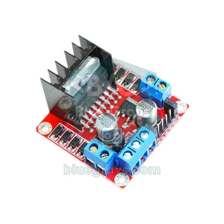
| Feature | L293D motor shield | L298N module |
|---|---|---|
| Number of motors | 4 DC, or 2 steppers + 2 servos | 2 DC or 1 stepper |
| Current per channel | 0.6 A continuous, 1.2 A peak | 2 A continuous, 3 A peak |
| Motor voltage | 4.5–25 V | 5–35 V |
| Voltage drop | About 1.5–2.6 V | About 2–3 V |
| Connection | Plugs onto the Uno, no wires | Jumper wires; you choose the pins |
| Pins used | 8 fixed pins + D9 and D10 for servos | 6 pins (ENA, IN1–IN4, ENB) |
| Library | AFMotor required | Not needed (digitalWrite, analogWrite) |
| ESP32 and Pico | Not suitable | Works directly |
| Best for | 4WD cars with TT motors, learning kits | Stronger motors, 2WD robots |
In short, if you're building a 4WD car with TT motors on an Arduino Uno, the L293D shield keeps the wiring to a minimum and puts all four motors on one board. If your motors are stronger, your board is an ESP32 or a Pico, or choosing the pins matters to you, the L298N is more flexible; details are in L298N DC Motor Control. If you want something more efficient than both, the MOSFET-based TB6612FNG has a very low voltage drop and makes your batteries last longer. We compare which motor type suits which job in DC Motor vs Servo vs Stepper Motor.
Can you use it with an ESP32, Raspberry Pi Pico or Mega?
It works fine with the Arduino Mega 2560: the shield sits on the Mega's first digital and analog pins, and AFMotor knows the Mega's timers. It does not work with the Uno R4, Leonardo, ESP32 or Raspberry Pi Pico, because AFMotor writes directly to the timer registers of the ATmega328P and ATmega2560. With an ESP32 selected, the build stops with 'DC_MOTOR_PWM_RATE' was not declared in this scope, and with a Leonardo selected it stops with #error "This chip is not supported!". Uno-shaped ESP32 boards (such as the ESPDuino-32) physically fit the shield, but the pin numbers and the 3.3 V signal level are different. On these boards it's much easier to use an L298N, a TB6612FNG or a single L293D chip instead of the shield. The L293D's inputs treat anything above 2.3 V as HIGH, so it works directly with 3.3 V boards:
| L293D pin | Function | Raspberry Pi Pico | ESP32 |
|---|---|---|---|
| 1 (1,2EN) | Speed (PWM) | GP15 | GPIO 25 |
| 2 (1A) | Direction 1 | GP14 | GPIO 26 |
| 7 (2A) | Direction 2 | GP13 | GPIO 27 |
| 3 and 6 (1Y, 2Y) | Motor terminals | To the motor | To the motor |
| 4, 5, 12, 13 | GND (heat also leaves through these pins) | GND | GND |
| 16 (VCC1) | Logic supply, 5 V | VBUS (pin 40) | 5V (VIN) |
| 8 (VCC2) | Motor supply | Battery positive | Battery positive |
1from machine import Pin, PWM
2import time
3
4en = PWM(Pin(15))                 # L293D pin 1 (1,2EN): hız / speed
5en.freq(1000)
6in1 = Pin(14, Pin.OUT)            # L293D pin 2 (1A): yön / direction
7in2 = Pin(13, Pin.OUT)            # L293D pin 7 (2A): yön / direction
8
9def motor(speed):                 # -100 … 100
10    in1.value(1 if speed > 0 else 0)
11    in2.value(1 if speed < 0 else 0)
12    en.duty_u16(int(abs(speed) * 655.35))
13
14while True:
15    motor(80)                     # ileri / forward
16    time.sleep(2)
17    motor(0)                      # dur / stop
18    time.sleep(0.5)
19    motor(-60)                    # geri / backward
20    time.sleep(2)
21    motor(0)
22    time.sleep(0.5)
The grounds of the Pico and the battery must be connected. On the ESP32 you build the same logic in the Arduino language: direction with digitalWrite and speed with analogWrite on the pins in the table. If these boards are new to you, start with What Is the ESP32? and What Is the Raspberry Pi Pico?.
Motors not turning: common mistakes and fixes
| Symptom | Likely cause | Fix |
|---|---|---|
| No motor turns, PWR LED is off | No motor power: EXT_PWR is empty or only USB is connected | Connect a 6–12 V battery to EXT_PWR; the motors won't turn until the LED is on |
| LED is on, code uploaded, but the motor doesn't move | No setSpeed() in the code, or the motor number doesn't match the terminal | Add setSpeed(200) in setup(); check that AF_DCMotor(1) matches M1 |
| Motor hums but doesn't turn | PWM value too low or battery weak | Start above 100; charge the battery or use two 18650 cells |
| "AFMotor.h: No such file or directory" | Library not installed, or V2 installed instead | Install the V1 Adafruit Motor Shield library from the Library Manager |
| "This chip is not supported!" or a "DC_MOTOR_PWM_RATE" error | Uno R4, Leonardo or ESP32 selected as the board | Select Uno or Mega under Tools > Board |
| Arduino resets when the motors start | Start-up current pulls the battery voltage down (brownout) | Remove the jumper and power the Arduino separately; solder a 100 nF capacitor across the motor terminals |
| Motor runs for a while then stops, chip is very hot | The L293D's thermal shutdown has kicked in | Reduce the load, use a soft start, add heatsinks or move to an L298N |
| Motors change direction at random | D4, D7, D8 or D12 is used for something else in the code | Move your sensors to A0–A5 |
| M1 and M2 speed doesn't change, M3 and M4 are fine | tone() or IRremote is using Timer2 | Move these motors to M3 and M4 or remove the conflicting code |
| One wheel spins backwards | Motor wires reversed in the terminal | Swap that motor's two wires |
| Board behaves strangely once the shield is fitted | The Uno's USB socket touches solder joints under the shield, or a pin is bent | Put insulating tape on top of the USB socket, straighten the pins and refit the shield |
Project ideas with the L293D motor shield
- Bluetooth-controlled 4WD car: A four-wheel-drive robot you drive from your phone with the code above.
- Obstacle-avoiding robot: A car that scans ahead with an HC-SR04 mounted on the servo on SER1 and turns towards the most open direction; the full guide is in Obstacle Avoiding Robot with Arduino.
- Line follower robot: Follow a black line on the floor with infrared sensors on A0–A3; PID tuning is covered in Line Follower Robot with Arduino.
- Camera slider: Move a camera slowly along a rail with a stepper motor and shoot time-lapse videos.
- Pan-tilt head: Plug two servos into the two servo headers and aim a camera or a laser on two axes; for more servos, see Arduino Robotic Arm.
- Automatic curtain or conveyor belt: Open and close a curtain with a DC motor depending on the light, or build a small conveyor belt.
Here's the summary of using the L293D motor shield correctly: install the V1 library, check the PWR LED, set the jumper to match your power setup, don't forget setSpeed(), connect sensors to A0–A5 and keep your motors below the 0.6 A limit. Follow these rules and a small shield can carry all the muscle of a four-motor robot on its own. In the BlueGrays app you'll find the Bluetooth-controlled car, obstacle-avoiding robot, stepper motor and servo projects step by step with circuit diagrams and code.
Frequently asked questions
How many motors can the L293D motor shield drive?
The shield can drive 4 DC motors at once, each independently forward, backward and at different speeds. Instead of DC motors you can also connect 2 steppers (the M1–M2 and M3–M4 pairs), or 2 DC motors plus 1 stepper. On top of that there are two servo headers; the servos are driven from D9 and D10 independently of the motors.
What is the PWR jumper on the L293D motor shield for?
With the jumper fitted, the shield's motor supply is connected to the Arduino's Vin line and both boards run from one source. If you power the Arduino from USB and the motors from a separate battery, you must remove the jumper. Connecting separate sources to both the DC jack and EXT_PWR with the jumper fitted shorts the two supplies together.
What battery should I use with the L293D motor shield?
For robot cars with TT motors, the best choice is two 18650 lithium cells (7.4 V); since the L293D loses about 2 V, the motors see 5.5–6 V. Four AA cells leave the motors only about 4 V, and a 9 V PP3 battery can't supply enough current to drive motors. Mind the polarity when connecting the battery to EXT_PWR, because the terminal has no reverse-polarity protection.
How do I fix "AFMotor.h: No such file or directory"?
This error means the AFMotor library isn't installed. Search for Adafruit Motor Shield in the Library Manager and install the Adafruit Motor Shield library whose description mentions V1. The V2 library is for a different board and doesn't contain the AFMotor.h file.
How much current can the L293D motor shield handle, and why does it get hot?
Each channel can deliver 0.6 A continuously and 1.2 A for very short peaks. Because the L293D's transistors drop about 2.6 V at 0.6 A, close to 1.5 W of heat is produced per motor; that's why the chip gets hot and shuts itself down when the limit is exceeded. Make sure your motors don't stall, and use a stronger driver such as the L298N for motors that continuously draw more than 0.6 A.
Is the L293D motor shield or the L298N better?
If you're building a 4WD car with TT motors on an Arduino Uno, the L293D shield is more practical because it plugs straight on without wires and has four motor channels. If you use stronger motors, an ESP32 or a Pico, or want to choose the pins yourself, the L298N with 2 A per channel is a better fit. Both lose about 2 V of the motor voltage.
Projects to build after reading this
See all projects
Bluetooth Controlled Car with L298N
Turn your phone into a remote and drive your own robot car. The Arduino receives commands from a remote-control app on your phone through a Bluetooth module and spins the wheels with a motor driver; t

Obstacle Avoidance Robot
How about building a smart vehicle that finds its own way? The Obstacle Avoidance Robot constantly scans its surroundings thanks to the ultrasonic sensor in front of it. When it encounters an obstacle
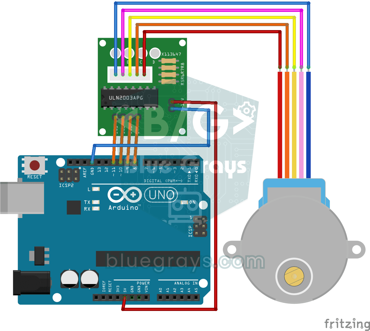
Using a Stepper Motor
A motor that turns step by step, exactly as far as you want, like the hand of a clock. Through a driver board, the Arduino turns a small stepper motor one full turn in one direction, waits a second, t
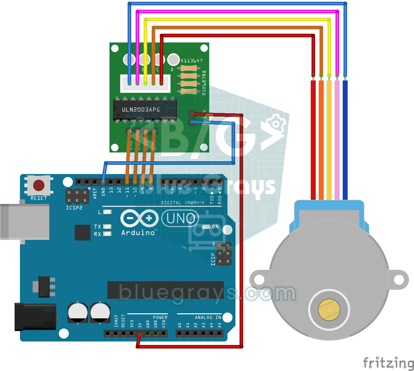
360-Degree Servo from a Stepper Motor
Teach an ordinary stepper motor to go to any angle you want, all the way around the circle. The Arduino works out how many steps each angle takes; the motor moves to 0, 90, 45, 180, 135 and 360 degree
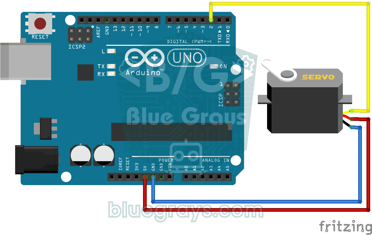
Using a Servo Motor
The arm of a small servo motor turns to three positions in turn: all the way to the start, right to the middle and all the way to the end, waiting two seconds at each stop. The Arduino tells the motor
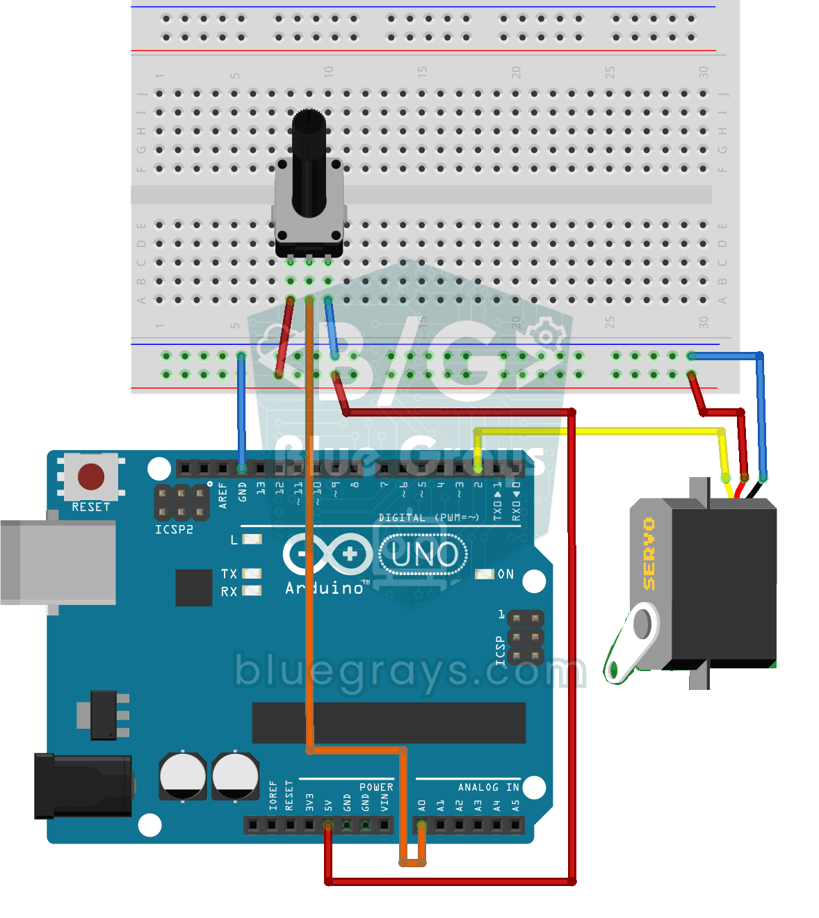
Servo Motor Operation with Potentiometer
As you turn the potentiometer knob, the servo motor's arm turns right along with it: one end of the knob means zero degrees, the other end means half a turn. The Arduino keeps reading the knob's posit
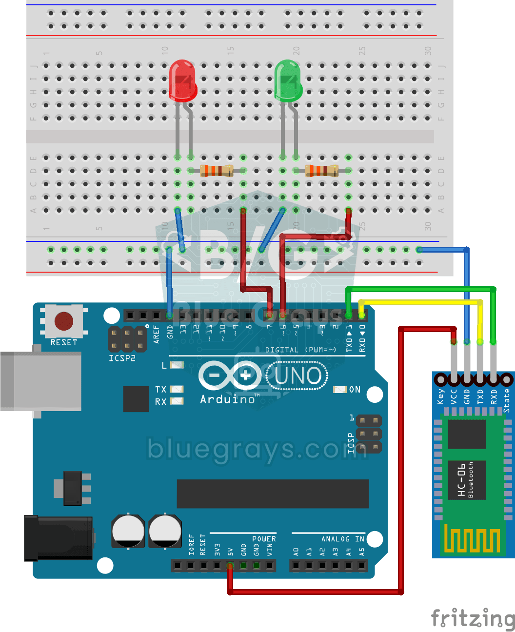
Control an LED from Your Phone via Bluetooth
A small rehearsal for switching the lights in your room on and off from your phone. The Bluetooth module passes the letters sent from your phone to the Arduino; one letter turns on the red LED, anothe

TCRT5000 Black and White Surface Detection
With the little sensor that acts as the eye of line-following robots, you can tell whether the floor is black or white. The TCRT5000 shines invisible light at the floor and checks how much of it bounc