
Raspberry Pi Pico Projects for Beginners: 20 Ideas With Code
20 Raspberry Pi Pico projects for beginners, from LEDs and button interrupts to PWM, sensors, OLED and servo, with a language, parts and difficulty table.

Looking for Raspberry Pi Pico projects for beginners and not sure where to start? This list is for you: we've put together 20 projects ordered from easy to hard, from blinking a single LED and button interrupts to a PWM breathing effect, reading sensors, an OLED display and a servo motor. One table shows which language to use for each project (MicroPython or C/C++), the parts you need and the difficulty, and the most instructive project of each level comes with working code.
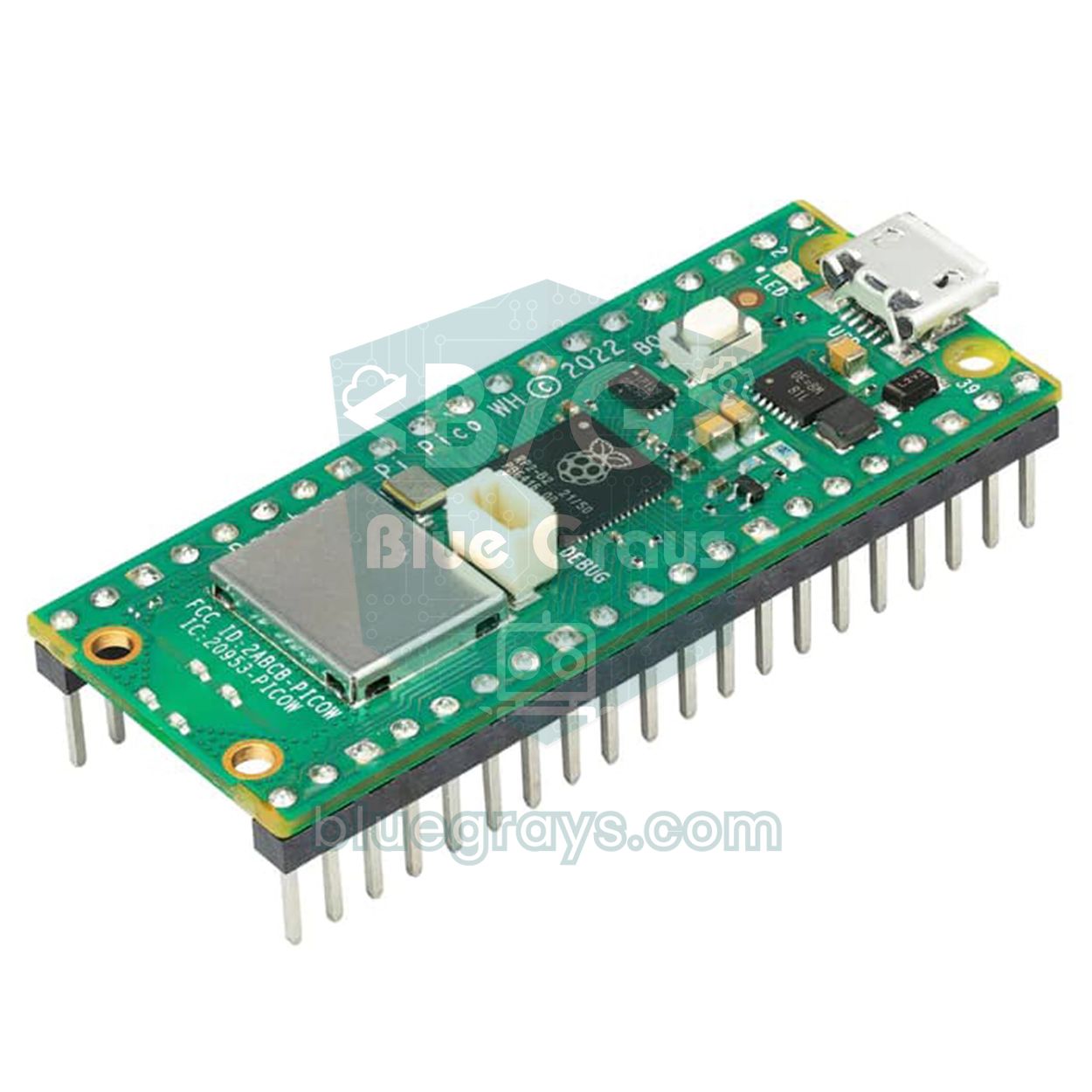
There are three reasons the Pico is such a good first board: it's cheap, MicroPython lets you run code without waiting for a compile, and every one of its 26 GPIO pins can output PWM. If you've just unboxed yours, go through the setup steps in What Is the Raspberry Pi Pico? first; here we assume your board already runs in Thonny and you can blink the onboard LED.
Before you start: what you need
- Board: Raspberry Pi Pico, Pico W or Pico 2. The wireless project (number 19) needs a Pico W.
- Breadboard and jumper wires: to build circuits without soldering; make sure your Pico has its pin headers soldered on.
- LEDs and resistors: 5–10 LEDs plus 220 Ω and 330 Ω resistors; use the LED resistor calculator to pick values.
- Inputs: 2–3 push buttons, a 10 kΩ potentiometer, an LDR and a 10 kΩ resistor.
- Sensors and outputs: HC-SR04, DHT11, HC-SR501 PIR, a passive buzzer, an SG90 servo, a 0.96 inch SSD1306 OLED and a WS2812B ring with 8–12 LEDs.
- Software: Thonny for MicroPython; the Arduino IDE with Earle Philhower's RP2040 core for C/C++.
MicroPython or C/C++?
The Pico supports both worlds, and most projects on this list can be written in either language. In MicroPython you type your code in Thonny, press Run and see the result within a second; when something goes wrong you get a clear message with a line number. C/C++ (the Arduino IDE or the Pico SDK) needs a compile step, but runs 10 to 100 times faster and lets you use thousands of libraries written for Arduino. If you're a beginner, do the first 19 projects in MicroPython and switch to C/C++ when you need speed or a ready-made library.
| Criterion | MicroPython | C/C++ (Arduino IDE) |
|---|---|---|
| Learning curve | Easy, basic Python is enough | Familiar if you know Arduino |
| Running code | Instant (with Thonny) | Compile and upload: 10–30 seconds |
| Speed | Slower, but enough for most projects | 10–100 times faster |
| Libraries | Built-in modules such as machine, neopixel, dht | Most Arduino libraries |
| Best for | Learning, reading sensors, quick experiments | Precise timing, USB keyboards, heavy maths |
20 Raspberry Pi Pico projects: language, parts and difficulty
| # | Project | Suggested language | Parts needed | Difficulty |
|---|---|---|---|---|
| 1 | Blink the onboard LED | MicroPython | Just the Pico | Easy |
| 2 | External LED (GP14) | MicroPython | LED, 220 Ω resistor | Easy |
| 3 | Traffic light | MicroPython | Red, yellow and green LED, 3 resistors | Easy |
| 4 | Police strobe effect | MicroPython | Red and blue LED, 2 resistors | Easy |
| 5 | Knight Rider scanner | MicroPython | 6 LEDs, 6 resistors | Easy |
| 6 | Toggle an LED with a button | MicroPython | Button, LED, resistor | Easy |
| 7 | Button interrupt (IRQ) and debounce | MicroPython | Button, LED, resistor | Medium |
| 8 | PWM breathing LED | MicroPython | LED, resistor | Easy |
| 9 | RGB LED colour cycle | MicroPython | RGB LED, 3 resistors | Easy |
| 10 | Play a melody on a passive buzzer | MicroPython | Passive buzzer | Easy |
| 11 | LED brightness with a potentiometer | MicroPython | 10 kΩ potentiometer, LED | Easy |
| 12 | Built-in temperature sensor | MicroPython | Just the Pico | Easy |
| 13 | Automatic night light with an LDR | MicroPython | LDR, 10 kΩ resistor, LED | Easy |
| 14 | PIR motion alarm | MicroPython | HC-SR501, active buzzer | Easy |
| 15 | HC-SR04 distance meter | MicroPython | HC-SR04, 1 kΩ and 2 kΩ resistors | Medium |
| 16 | OLED thermometer | MicroPython | SSD1306 OLED, DHT11 | Medium |
| 17 | Servo control with a potentiometer | MicroPython | SG90 servo, 10 kΩ potentiometer | Medium |
| 18 | WS2812B LED ring animation | MicroPython | WS2812B ring (8–12 LEDs) | Medium |
| 19 | Control an LED over Wi-Fi with the Pico W | MicroPython | Pico W, LED | Hard |
| 20 | USB macro keyboard | C/C++ (Arduino IDE) | 3–4 buttons | Hard |
The order isn't random: each project adds one step on top of what you learned in the previous one. The first six teach digital output and input, 7–10 cover interrupts and PWM, 11–15 analog and digital sensors, 16–18 a display, a servo and PIO-driven LEDs, and the last two show Pico-specific abilities such as Wi-Fi and USB. Below we walk through each level with its circuit and give you the code for the most instructive projects.
Level 1: LED and button projects (1–6)
In the first project you blink the onboard LED with Pin(25) (on the Pico W and Pico 2 W, use Pin("LED")). In the second you connect an external LED to GP14 (physical pin 19) through a 220 Ω resistor; the resistor can sit on either the long or the short leg, as long as it's in series. The traffic light lights the three LEDs on GP11, GP12 and GP13 in sequence, the police strobe flashes a red and a blue LED in quick bursts, and the Knight Rider scanner sweeps a light back and forth across six LEDs on GP9–GP14. In these three projects, keeping the pins in a list and looping over it with a for loop cuts your code in half.
In project six the button goes to GP2 with its other leg to GND, and the Pico's internal pull-up resistor is switched on, so the pin reads 1 when the button is released and 0 when it's pressed. To toggle the LED on each press you need to store the previous button state in a variable and only count the change from 1 to 0. You'll find why buttons bounce and how pull-ups work in How to Connect a Button to Arduino; the same rules apply to the Pico.
Level 2: Button interrupts, PWM and sound (7–10)
Checking a button over and over inside the loop (polling) is fine for simple projects, but your code can miss presses while it's busy with something else. With an interrupt (IRQ), the Pico calls your function the moment the pin changes level. The code below is the whole of project 7: every press toggles the LED on GP14, and a 200 ms time filter stops mechanical bounce from being read as a double press.
1from machine import Pin
2import time
3
4led = Pin(14, Pin.OUT)                     # GP14 + 220 Ω direnç / GP14 + 220 Ω resistor
5button = Pin(2, Pin.IN, Pin.PULL_UP)       # butonun diğer ucu GND / other leg to GND
6last_ms = 0                                # son geçerli basış / last valid press
7
8def on_press(pin):
9    global last_ms
10    now = time.ticks_ms()
11    if time.ticks_diff(now, last_ms) > 200:   # 200 ms sıçrama filtresi / 200 ms debounce
12        led.toggle()
13        last_ms = now
14
15button.irq(trigger=Pin.IRQ_FALLING, handler=on_press)   # basınca 1→0 / press pulls 1→0
16
17while True:
18 time.sleep(1) # ana döngü boşta, iş kesmede / main loop idle, work in the IRQProject eight is the classic PWM example. Every GPIO pin on the Pico can output PWM, and in MicroPython you set the duty cycle with duty_u16() from 0 to 65535. If you raise the brightness linearly, your eye won't see it as natural: the change looks too fast at low levels and too slow at high ones. The code below uses a cosine curve for a smooth breathing rhythm and squares the value to get a brightness curve closer to how your eye perceives light. You can read the background in What Is PWM?
1from machine import Pin, PWM
2import math, time
3
4led = PWM(Pin(14))
5led.freq(1000)                             # 1 kHz, titreme görünmez / 1 kHz, no visible flicker
6
7while True:
8    for step in range(200):
9        level = (1 - math.cos(step / 200 * 2 * math.pi)) / 2   # 0 → 1 → 0 yumuşak / smooth 0 → 1 → 0
10        led.duty_u16(int(level * level * 65535))             # kare alma göze doğal gelir / squaring looks natural
11        time.sleep_ms(15)                                      # 200 × 15 ms = 3 s bir nefes / one 3 s breath
In project nine you apply the same idea to three channels: connect the red, green and blue legs of an RGB LED to GP11, GP12 and GP13, each through a resistor, and shift the three duty values out of phase so the colours blend into each other. With common-anode LEDs, remember to invert the values; the details are in How to Use an RGB LED. In project ten you change the PWM frequency instead: wire a passive buzzer to a pin, call freq(440) and it plays an A note; a duty of 32768 (50 percent) gives the loudest sound, and looping over a list of notes gives you a melody.
Level 3: Sensor projects (11–15)
The Pico's analog inputs are GP26, GP27 and GP28, and read_u16() returns a value from 0 to 65535 (the chip measures 12 bits internally and MicroPython scales the result to 16 bits). In project eleven you connect the middle pin of a potentiometer to GP26 and write the reading straight into the LED's duty value. Project twelve needs no extra parts: channel 4 of the ADC is wired to a temperature sensor inside the chip, and the temperature is T = 27 − (V − 0.706) / 0.001721. Because it measures the chip rather than the room, expect it to be a few degrees off. In project thirteen you build a voltage divider from an LDR and a 10 kΩ resistor and switch on an LED when the reading crosses a darkness threshold; the voltage divider calculator makes the maths easy.
The HC-SR501 PIR sensor in project fourteen is powered from 5 V but its output is 3.3 V, so it can go straight to a GPIO; when it detects motion the pin goes to 1 for a few seconds. For its time and sensitivity knobs, see PIR Motion Sensor. Project fifteen needs a bit more care: the HC-SR04 runs on 5 V and its ECHO pin outputs a 5 V pulse. The code below sends a 10 microsecond pulse to TRIG, measures the length of the echo with time_pulse_us() and works out the distance from the speed of sound.
1from machine import Pin, time_pulse_us
2import time
3
4trig = Pin(17, Pin.OUT)                    # GP17 → TRIG
5echo = Pin(16, Pin.IN)                     # GP16 ← ECHO (1 kΩ + 2 kΩ bölücüyle / through a 1k + 2k divider)
6
7def distance_cm():
8    trig.low()
9    time.sleep_us(2)
10    trig.high()
11    time.sleep_us(10)                      # 10 µs tetik darbesi / 10 µs trigger pulse
12    trig.low()
13    t = time_pulse_us(echo, 1, 30000)      # en çok 30 ms bekle (~5 m) / wait up to 30 ms (~5 m)
14    if t < 0:
15        return None                        # yankı yok / no echo
16    return t * 0.0343 / 2                  # 343 m/s, gidiş-dönüş / round trip
17
18while True:
19    d = distance_cm()
20    print("Mesafe / Distance:", "---" if d is None else "%.1f cm" % d)
21 time.sleep_ms(200)Level 4: OLED display, servo and NeoPixel (16–18)
In project sixteen you show the temperature and humidity from a DHT11 on a 0.96 inch OLED display. The dht module the DHT11 needs is already built into the Pico's MicroPython firmware; for the OLED you copy the ssd1306.py driver file onto the Pico. The display connects over I2C to GP4 (SDA) and GP5 (SCL). The display code is covered in How to Use an SSD1306 OLED Display, and the sensor in DHT11 Temperature and Humidity Sensor.
In project seventeen you turn an SG90 servo with a potentiometer. A servo expects a 50 Hz signal and reads the angle from the width of the pulse: roughly 500 microseconds is 0 degrees and 2500 microseconds is 180 degrees. In MicroPython, duty_ns() lets you write the pulse width directly in nanoseconds, which makes the maths very simple:
1from machine import Pin, PWM, ADC
2import time
3
4servo = PWM(Pin(15))                       # GP15 → servo sinyal (turuncu) / signal (orange)
5servo.freq(50)                             # 50 Hz = 20 ms periyot / 20 ms period
6pot = ADC(26)                              # GP26 (ADC0) ← potansiyometre orta ucu / pot wiper
7
8def set_angle(angle):
9    pulse_us = 500 + angle * 2000 // 180   # 0° = 500 µs, 180° = 2500 µs
10    servo.duty_ns(pulse_us * 1000)
11
12while True:
13    angle = pot.read_u16() * 180 // 65535  # 0–65535 → 0–180°
14    set_angle(angle)
15 time.sleep_ms(20) # her periyotta bir güncelleme / one update per periodIn project eighteen you drive a WS2812B LED ring with MicroPython's built-in neopixel module. These LEDs need microsecond-accurate timing, and the Pico handles it without tying up the CPU thanks to its programmable I/O blocks, called PIO. We explain step by step how to use PIO and the second core in Pico PIO and Dual Core. A small ring with 8–12 LEDs can run from the VBUS pin; longer strips need a separate 5 V supply.
Level 5: Wi-Fi and a USB keyboard with the Pico W (19–20)
In project nineteen the Pico W joins your home network and switches an LED from buttons on a web page you open on your phone. With MicroPython's network and socket modules you can write a working web server in 40–50 lines; for the step-by-step setup, see Pico W Wi-Fi Web Server. In project twenty your Pico shows up on your computer as a keyboard: give each button a shortcut or a piece of text and you have your own macro pad. C/C++ is the easier route here, because the Pico core for the Arduino IDE comes with the Keyboard library.
The same project in C/C++: the Pico in the Arduino IDE
Once you install Earle Philhower's Raspberry Pi Pico/RP2040 package from the Boards Manager in the Arduino IDE, you program the Pico with the Arduino commands you already know. You use the GP number as the pin number (14 for GP14), analogWrite() works in the 0–255 range by default and attachInterrupt() works on every pin. For the first upload you may need to plug the Pico in while holding the BOOTSEL button. The code below combines projects 7 and 8: the LED breathes, stops when you press the button and carries on when you press it again.
1// Arduino IDE + Raspberry Pi Pico (Earle Philhower çekirdeği / core)
2const int LED_PIN = 14;      // GP14 (fiziksel pin 19 / physical pin 19)
3const int BUTTON_PIN = 2;    // GP2, diğer ucu GND / other leg to GND
4
5volatile bool breathing = true;            // kesmede değişir / changed in the interrupt
6volatile unsigned long lastPress = 0;
7
8void onPress() {
9  unsigned long now = millis();
10  if (now - lastPress > 200) {             // 200 ms sıçrama filtresi / 200 ms debounce
11    breathing = !breathing;
12    lastPress = now;
13  }
14}
15
16void setup() {
17  pinMode(LED_PIN, OUTPUT);
18  pinMode(BUTTON_PIN, INPUT_PULLUP);
19  attachInterrupt(digitalPinToInterrupt(BUTTON_PIN), onPress, FALLING);
20}
21
22void loop() {
23  if (!breathing) {                        // butonla durdurulduysa LED sönük / paused by the button
24    analogWrite(LED_PIN, 0);
25    return;
26  }
27  for (int v = 0; v <= 255; v++) { analogWrite(LED_PIN, v); delay(4); }   // yavaşça yan / fade in
28  for (int v = 255; v >= 0; v--) { analogWrite(LED_PIN, v); delay(4); }   // yavaşça sön / fade out
29}
Common mistakes and how to fix them
- Wrong pin number: your code uses the GP number, not the physical pin number. GP14 is pin 19 on the board; you can see the full map in the Pinout tool.
- The onboard LED won't light on a Pico W: on the Pico W the LED is wired to the wireless chip; use Pin("LED") instead of Pin(25).
- The code doesn't run once you unplug it from the computer: save the file on the Pico as main.py; that's the only file the Pico runs by itself at power-up.
- The servo jitters or the Pico resets: the servo is powered from 3V3 or the grounds aren't shared; power it from 5 V and add a 470 µF capacitor across the supply.
- The analog value is always 0 or always 65535: the sensor is on a pin other than GP26–GP28, or you're reading an outer leg of the potentiometer instead of the middle one.
- duty() from older examples throws an error: on the Pico, MicroPython PWM uses duty_u16() or duty_ns().
- One press is detected several times: that's mechanical bounce; add a 150–200 ms time filter like the one in the interrupt code.
Once you've finished these 20 projects in order, you'll have used the Pico's digital inputs and outputs, interrupts, PWM, the ADC, I2C, PIO and Wi-Fi, which is almost everything you need to start designing your own projects. To feel more at home in MicroPython, MicroPython Basics is a good next step. In the BlueGrays app you can try Pico projects such as the onboard LED, traffic light, police strobe, Knight Rider, button interrupt, PWM breathing effect and RGB colour cycle step by step, each with its circuit diagram and code.
Frequently asked questions
What can you make with a Raspberry Pi Pico?
You can build LED effects, sensor-based measuring devices, OLED thermometers, servo and motor controllers, USB keyboards and game controllers, and with a Pico W, home automation projects you control from your phone. The Pico is a microcontroller, not a computer, so it isn't suited to playing video or running desktop programs.
Is the Raspberry Pi Pico good for beginners?
Yes. With MicroPython you can use what you know about Python straight away and run code without waiting for a compile. The main thing to watch is that the pins run at 3.3 V, so sensors with 5 V outputs need a voltage divider or a level shifter.
Should I learn MicroPython or C++ for the Pico?
If you're new to both programming and electronics, start with MicroPython: the error messages are clear and the test cycle is short. Move to C/C++ when you need precise timing, more speed or a library that only exists for Arduino; the Pico supports both.
Can a Raspberry Pi Pico drive a servo directly?
On the signal side, yes: any GPIO pin can control a servo like the SG90 with 50 Hz PWM. Power the servo from VBUS or an external 5 V supply rather than the 3V3 pin, though, and connect the grounds together.
What's the difference between the Pico and the Pico W?
Both use the same RP2040 chip; the Pico W adds a 2.4 GHz Wi-Fi and Bluetooth chip. Every project that doesn't need Wi-Fi runs on both, and the only change is that the Pico W's onboard LED is controlled with Pin("LED").
Can I use Arduino code on a Raspberry Pi Pico?
If you install Earle Philhower's RP2040 package in the Arduino IDE, most Arduino sketches run with small changes, using GP numbers as pin numbers. Code that uses AVR-specific registers, or circuits that assume 5 V logic, need adapting.
Projects to build after reading this
See all projects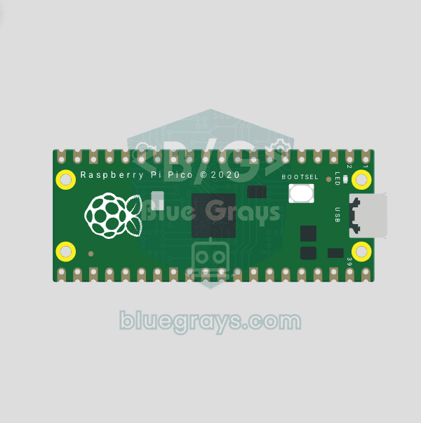
Raspberry Pi Pico Onboard LED Blink (Pico and Pico W)
The opening project of the Raspberry Pi Pico series! We blink the Pico's green built-in LED to confirm the board works, the classic "Hello World" first experiment. No external parts needed, just the Pico and a USB cable. The code is written in MicroPython, the language officially supported by the Raspberry Pi Foundation.
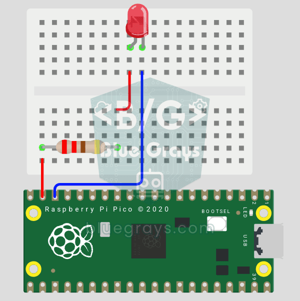
Raspberry Pi Pico: Controlling an External LED (Breadboard)
The next step after the Pico's built-in LED: connect an external LED on a breadboard and control it through pin GP14. You'll learn how to use any of the Pico's GPIO pins as an output, the LED's polarity (long leg = anode/+, short leg = cathode/–) and why a current-limiting resistor (220Ω) is a must. Without the resistor, too much current flows through the LED and it can burn out.
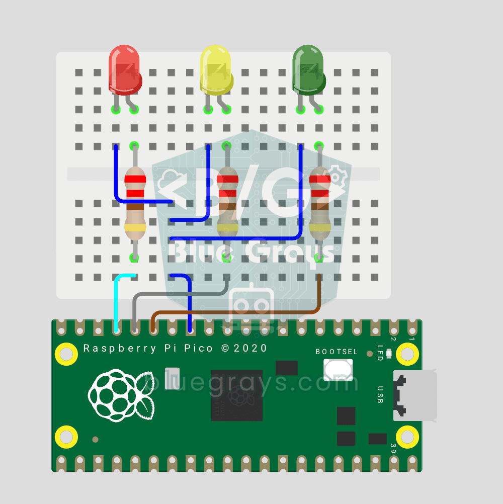
Raspberry Pi Pico Traffic Light Simulator (3 LEDs Sequential)
We recreate real traffic light logic with red, yellow and green LEDs, the first Pico project to move up to 3 LEDs! Green says "go" for 4 seconds, yellow "get ready" for 1.5 seconds, red "stop" for 3 seconds, and red+yellow "set off" for 1 second (the European traffic light pattern). You'll learn to define functions (def all_off()), state machine logic and multi-GPIO synchronization.
Raspberry Pi Pico Police Strobe Light Effect (Red + Blue)
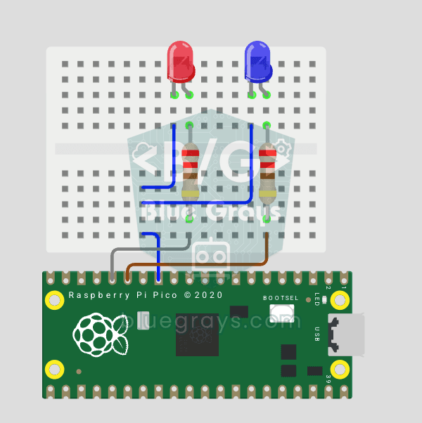
We simulate a police car's light bar with a Raspberry Pi Pico in its simplest form! The red and blue LEDs take turns (flip-flop): while red is on, blue is off, and they swap every 0.3 seconds, forever. The code writes the two steps directly in a single while True loop; the speed is set with the WAIT_MS constant.
Raspberry Pi Pico Knight Rider LED Scanner (6 LED Back-Forth)
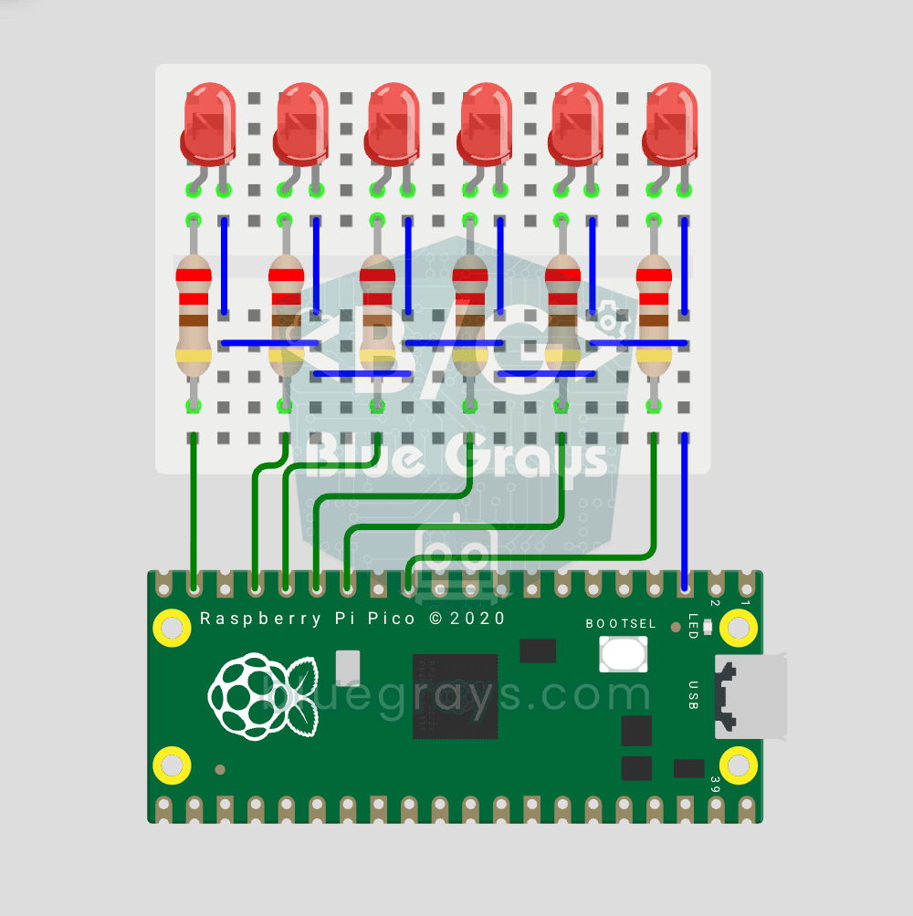
Classic "Knight Rider" LED scanner effect with Pico! 6 LEDs go left-to-right, then right-to-left, forever. Like the front grille of KITT car from the iconic 80s TV series. This project is an upgrade of the Chasing LED project: same 6 LED circuit (GP9-GP14), different code pattern. Learn reversed() function for list reversal, two separate for loops for back-and-forth pattern, and generating multiple animations on same circuit.
Raspberry Pi Pico Button Debounce: IRQ vs Software Polling
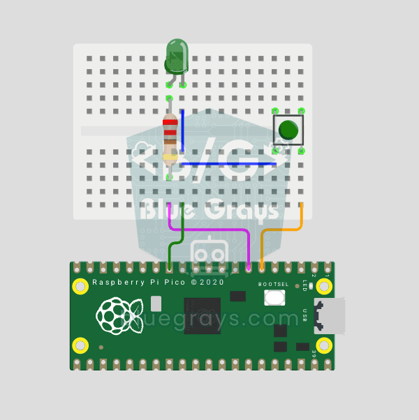
If one press of a button made your code count 3-4 times, the culprit is contact bounce: the button's metal contacts open and close many times within microseconds as they touch! In this project we count the same button in 2 different ways and compare them side by side in Serial: RAW polling (catches the bounce and miscounts) and IRQ + software debounce (counts correctly).
Raspberry Pi Pico PWM LED Fade (Breathing Effect)
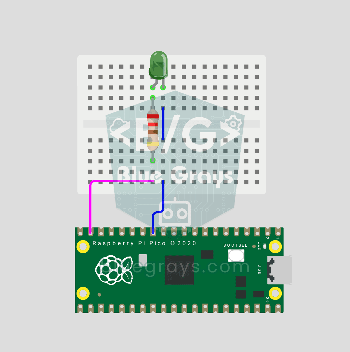
The LED doesn't just blink anymore, it breathes! With the Raspberry Pi Pico's PWM (Pulse Width Modulation), the LED's brightness slowly rises and then slowly fades, a calm "breathing" effect like a sleeping laptop's light. You'll learn the machine.PWM class, the 16-bit brightness value from 0–65535 with duty_u16() and the PWM frequency.
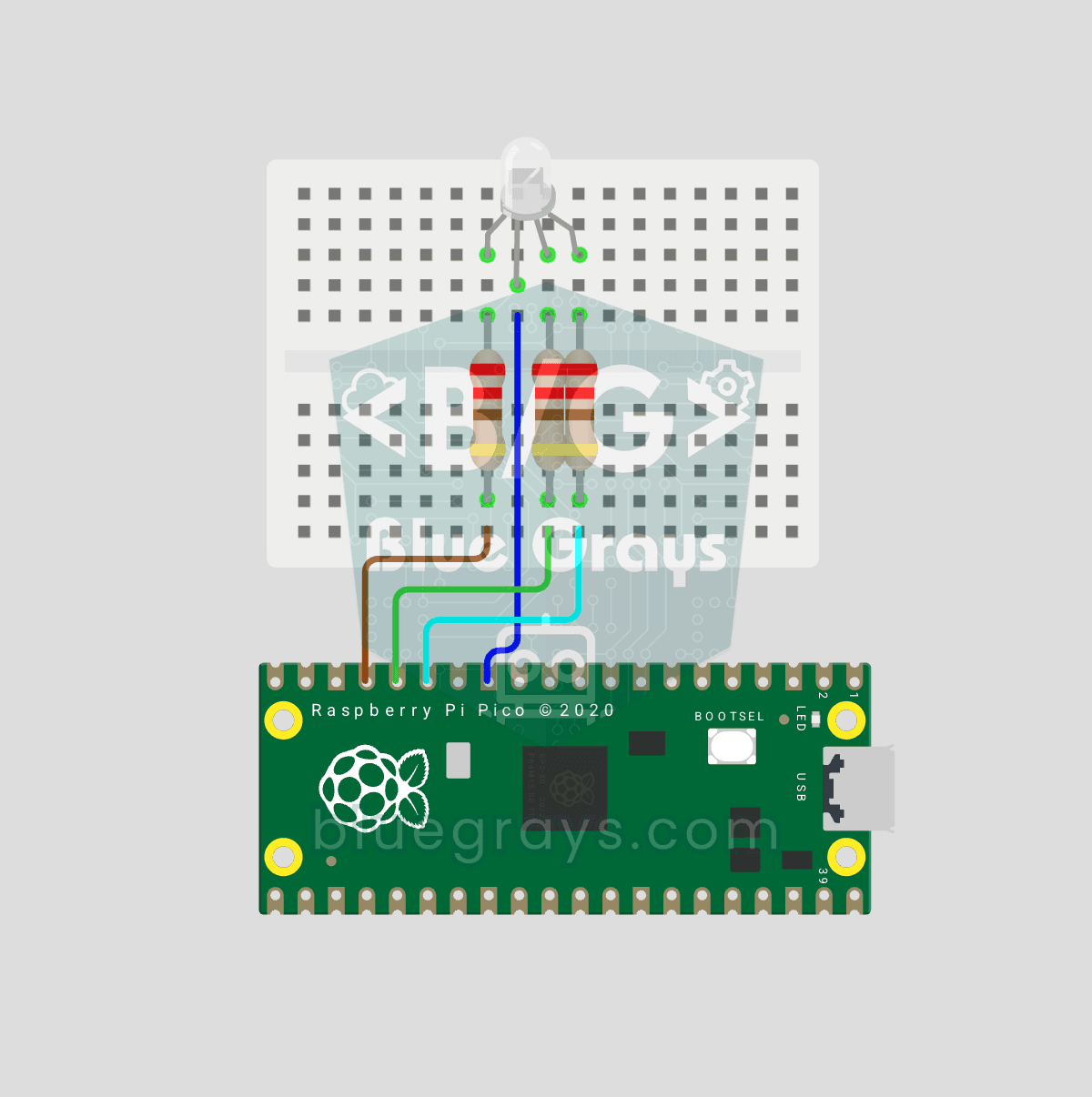
Raspberry Pi Pico RGB LED Color Cycle (3-Channel PWM)
One LED, millions of colors! An RGB LED actually holds 3 separate LEDs: red, green and blue. Set the brightness of each one separately with the Pico's 3 PWM channels and the colors mix: red + green = yellow, green + blue = cyan, all three = white. In this project the LED cycles through 8 colors.