
TCS3200 Color Sensor with Arduino: Wiring, Calibration and Code
How the TCS3200 color sensor works: S0–S3 settings, reading R, G, B with pulseIn, white and black calibration, color sorting, ESP32, Pico and TCS34725 code.
The TCS3200 color sensor is the most widely used color detection module in Arduino projects: it measures the color of the surface in front of it by splitting it into red, green and blue components. It converts the light captured by a photodiode array directly into a frequency: the more red light a surface reflects, the higher the frequency on the red channel. There's no analog reading or special communication protocol involved; you can read the R, G and B values in a few lines with Arduino's pulseIn() command. Candy sorting machines, color-recognizing robots, vehicles that change direction at colored marks on the floor and lamps that copy the color of an object held in front of them are all built with this sensor.
In this guide you'll see, step by step, what's inside the sensor, what the S0–S3 pins do, how to wire it to an Arduino Uno, ESP32 and Raspberry Pi Pico, how to take raw readings, how to do a white and black calibration, and an algorithm that works out which color a reading belongs to. Then we'll build the logic of a machine that sorts objects by color, and finally compare it with the TCS34725, a sensor that works over I2C.
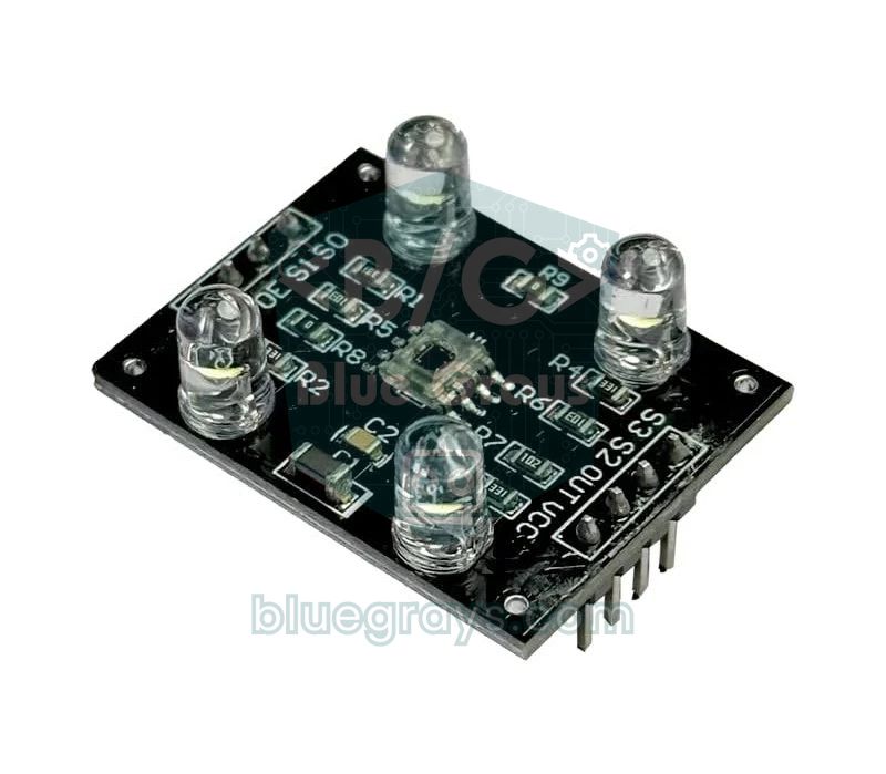
What is the TCS3200 color sensor and how does it work?
The TCS3200 chip at the heart of the module (its older version is called the TCS230) has 64 photodiodes in an 8×8 grid on its surface. Sixteen of them sit under red filters, 16 under green, 16 under blue, and the remaining 16 have no filter (clear) and see the total amount of light. The 16 photodiodes of each color are connected in parallel, and the S2 and S3 pins choose which group is measured. Because the photodiodes of different colors are interleaved across the array, light falling on one corner of the surface affects all color groups equally.
The small current produced by the selected photodiode group goes to a current-to-frequency converter inside the chip. This circuit generates a square wave with a 50% duty cycle, and the frequency of the wave is directly proportional to light intensity. So what you measure isn't a voltage but the number of pulses per second: a few hertz in complete darkness, tens of kilohertz when held close to a white surface. The nice thing about a frequency output is that it's robust against noise and can be connected to any digital pin on the Arduino. If you only want to measure how strong the light is, an LDR light sensor is a simpler option; the TCS3200 does the same job separately for three colors.
| Feature | Value |
|---|---|
| Chip | TCS3200 (older version TCS230, pin compatible) |
| Photodiode array | 8×8 = 64: 16 red, 16 green, 16 blue, 16 clear |
| Output | Square wave with 50% duty cycle, frequency proportional to light |
| Full-scale frequency (typical) | 600 kHz (100%), 120 kHz (20%), 12 kHz (2%) |
| Supply voltage | 2.7–5.5 V |
| Chip current | 1.4 mA typical (the module LEDs' current comes on top) |
| Control pins | S0, S1 (frequency scaling), S2, S3 (color filter), OE (output enable, active LOW) |
| Recommended distance | About 1–3 cm, the same for every reading |
| Lighting | 4 white LEDs on the module |
S0–S3 pins: frequency scaling and color filter selection
Four control pins set how the TCS3200 behaves. S0 and S1 scale down the output frequency: at 100% the pulses shrink to a few microseconds and push the limits of the Arduino Uno's measurement accuracy, while at 2% the pulses get longer but fewer of them arrive in the same time. S2 and S3 select which color filter is read. You connect these pins to the Arduino's digital outputs and set them from the code before each reading.
| S0 | S1 | Output frequency scaling | When to use it |
|---|---|---|---|
| LOW | LOW | Power down | To put the sensor to sleep in battery projects |
| LOW | HIGH | 2% (typically up to 12 kHz) | Slow processors, MicroPython and interrupt counting |
| HIGH | LOW | 20% (typically up to 120 kHz) | The best setting for Arduino and pulseIn |
| HIGH | HIGH | 100% (typically up to 600 kHz) | Fast measurements with a hardware counter |
| S2 | S3 | Photodiode group read |
|---|---|---|
| LOW | LOW | Red filter |
| LOW | HIGH | Blue filter |
| HIGH | LOW | No filter (clear, total light) |
| HIGH | HIGH | Green filter |
TCS3200 wiring: Arduino Uno, ESP32 and Pico
| Module pin | Arduino Uno | ESP32 | Raspberry Pi Pico |
|---|---|---|---|
| VCC | 5V | 3V3 | 3V3(OUT), pin 36 |
| GND | GND | GND | GND |
| S0 | D4 | GPIO 32 | GP2 |
| S1 | D5 | GPIO 33 | GP3 |
| S2 | D6 | GPIO 25 | GP4 |
| S3 | D7 | GPIO 26 | GP5 |
| OUT | D8 | GPIO 27 | GP6 |
| OE | GND | GND | GND |
The four white LEDs on the module light the surface the same way for every reading, so results stay more consistent even when the room lighting changes. Some boards have a separate LED pin to switch the LEDs on and off, while on others the LEDs light up as soon as power is applied; check the labels on your own board. For the best results, wrap the sensor in a black tube or cardboard, bring the object to the same distance every time and avoid shiny, reflective surfaces. You can check your board's pin layout in the Pinout tool.
Step by step: reading R, G and B with pulseIn
- Wire the module as in the table above; connect OE to GND and VCC to 5V.
- Select 20% frequency scaling by setting S0 HIGH and S1 LOW.
- For red, set S2 and S3 LOW and wait a few milliseconds for the output to settle.
- Measure the length of the LOW part of the pulse in microseconds with pulseIn(OUT, LOW); average 10 readings to reduce noise.
- Repeat the same for green (S2 HIGH, S3 HIGH) and blue (S2 LOW, S3 HIGH).
- Watch the results in the Serial Monitor at 9600 baud and hold sheets of paper in different colors in front of the sensor.
1// TCS3200 ile ham R, G, B okuma / Raw R, G, B reading with the TCS3200
2const int S0 = 4;
3const int S1 = 5;
4const int S2 = 6;
5const int S3 = 7;
6const int OUT_PIN = 8;
7
8// Filtreyi seçer, 10 darbenin ortalama LOW süresini döndürür (µs) / Selects a filter, returns the average LOW time of 10 pulses (µs)
9unsigned long readPulse(bool s2, bool s3) {
10  digitalWrite(S2, s2 ? HIGH : LOW);
11  digitalWrite(S3, s3 ? HIGH : LOW);
12  delay(5);                                           // çıkışın oturmasını bekle / let the output settle
13  unsigned long total = 0;
14  int count = 0;
15  for (int i = 0; i < 10; i++) {
16    unsigned long t = pulseIn(OUT_PIN, LOW, 50000UL); // 50 ms zaman aşımı / 50 ms timeout
17    if (t > 0) {
18      total += t;
19      count++;
20    }
21  }
22  return count > 0 ? total / count : 50000UL;         // darbe yoksa çok karanlık / no pulse means very dark
23}
24
25void setup() {
26  pinMode(S0, OUTPUT);
27  pinMode(S1, OUTPUT);
28  pinMode(S2, OUTPUT);
29  pinMode(S3, OUTPUT);
30  pinMode(OUT_PIN, INPUT);
31  digitalWrite(S0, HIGH);                             // S0=HIGH, S1=LOW: %20 ölçek / 20% scaling
32  digitalWrite(S1, LOW);
33  Serial.begin(9600);
34}
35
36void loop() {
37  unsigned long r = readPulse(false, false);          // kırmızı filtre / red filter
38  unsigned long g = readPulse(true, true);            // yeşil filtre / green filter
39  unsigned long b = readPulse(false, true);           // mavi filtre / blue filter
40  Serial.print("R: ");
41  Serial.print(r);
42  Serial.print("  G: ");
43  Serial.print(g);
44  Serial.print("  B: ");
45  Serial.println(b);
46  delay(500);
47}
The most important point in this code is that the number you read is inversely proportional to light: the smaller the value, the more light comes from that color. When you hold up a red sheet, you'll see output like "R: 24 G: 68 B: 52"; the smallest number is on the red channel. The 50,000 µs timeout passed to pulseIn stops the code from waiting for the default 1 second when no pulse arrives; if no pulse is caught at all, the function returns 50,000, which means "very dark". If you have trouble reading the serial output, take a look at the Arduino Serial Monitor guide.
White and black calibration: turning raw values into 0–255
Raw values on their own are misleading, because the three photodiode groups don't have the same sensitivity and the module's white LEDs don't emit every color equally. That's why even a perfectly white sheet gives different numbers on the three channels. Calibration removes these differences and places each channel between 0 (black) and 255 (white); it's the same idea as white balance in a camera. Do the calibration where the sensor will actually work, under the same light and at the same distance; a calibration done on your desk won't hold inside the machine's enclosure.
- Mount the sensor in a fixed holder and set the measuring distance (for example 1.5 cm) so it won't change.
- Put a plain white sheet in front of it, read the R, G and B values several times with the code above and write down their averages as the white reference; these are the smallest values.
- Put a matte black sheet or felt in the same spot and write down the readings as the black reference; these are the largest values.
- Enter these six numbers into the WHITE_ and BLACK_ constants at the top of the code below and upload it.
- Check that all three channels read close to 255 on white paper and close to 0 on black; if not, repeat the measurement with the same light and distance.
Watch out for a mistake made in many examples: converting the pulse width straight to 0–255 with map() doesn't give the right result, because light is proportional to frequency, not to pulse width. The correct way is to convert the width to frequency (1/t) first and then scale it: level = (f − f_black) / (f_white − f_black) × 255. Let's look at an example: you measured 20 µs on white, 200 µs on black, and the object gave 40 µs. map() turns this into 226, while the frequency method gives 113. The object's frequency is exactly half of white's, and once the black level is subtracted that corresponds to about 44% of the scale, or 113; map(), on the other hand, shows colors much lighter than they are and makes it harder to tell dark shades apart.
Color sorting algorithm: which color is this reading?
The calibrated R, G, B values still depend on the amount of light: when the same red object moves a little closer to the sensor, all three values rise together. To fix this, we divide each value by the total: r = R / (R + G + B), and the same for g and b. These color ratios stay almost constant even when distance and brightness change a little. Then you compare them with reference ratios you measured and saved once for each color, and pick the nearest neighbor. For the comparison it's enough to add up the squares of the ratio differences; the smaller this number, the more similar the colors. If even the nearest reference is farther than a certain threshold, the result is "unknown". If the total light is very low, the object is treated as black, and if all three channels are very high, as white; these two cases can't be told apart by ratios, so they are checked first.
1// TCS3200 ile kalibrasyonlu renk tanıma / Calibrated color recognition with the TCS3200
2const int S0 = 4, S1 = 5, S2 = 6, S3 = 7, OUT_PIN = 8;
3
4// Kalibrasyonda ölçtüğün süreler (µs), kendi değerlerinle değiştir / Pulse widths from your calibration (µs), use your own
5const float WHITE_R = 16, WHITE_G = 20, WHITE_B = 18;     // beyaz kağıt / white paper
6const float BLACK_R = 140, BLACK_G = 170, BLACK_B = 150;  // siyah kağıt / black paper
7
8struct ColorRef {
9  const char *name;
10  float r, g, b;                                          // renk oranları, toplamı 1 / color ratios, sum is 1
11};
12
13// Örnek referanslar, kendi ölçümlerinle değiştir / Sample references, replace with your own measurements
14ColorRef refs[] = {
15  {"Kirmizi / Red",    0.58, 0.20, 0.22},
16  {"Turuncu / Orange", 0.55, 0.30, 0.15},
17  {"Sari / Yellow",    0.42, 0.40, 0.18},
18  {"Yesil / Green",    0.24, 0.46, 0.30},
19  {"Mavi / Blue",      0.18, 0.30, 0.52},
20  {"Mor / Purple",     0.40, 0.20, 0.40}
21};
22const int REF_COUNT = sizeof(refs) / sizeof(refs[0]);
23const float MAX_DIST = 0.02;                              // bundan uzaksa bilinmiyor / farther than this is unknown
24
25unsigned long readPulse(bool s2, bool s3) {
26  digitalWrite(S2, s2 ? HIGH : LOW);
27  digitalWrite(S3, s3 ? HIGH : LOW);
28  delay(5);
29  unsigned long total = 0;
30  int count = 0;
31  for (int i = 0; i < 10; i++) {
32    unsigned long t = pulseIn(OUT_PIN, LOW, 50000UL);
33    if (t > 0) {
34      total += t;
35      count++;
36    }
37  }
38  return count > 0 ? total / count : 50000UL;
39}
40
41// Süreyi frekansa çevirip 0-255 arasına ölçekler / Converts the pulse width to frequency and scales it to 0-255
42float toLevel(unsigned long t, float tWhite, float tBlack) {
43  float f = 1.0 / t;                                      // ışık frekansla orantılı / light is proportional to frequency
44  float fWhite = 1.0 / tWhite;
45  float fBlack = 1.0 / tBlack;
46  float level = (f - fBlack) / (fWhite - fBlack) * 255.0;
47  return constrain(level, 0.0, 255.0);
48}
49
50// En yakın referans rengi bulur / Finds the nearest reference color
51const char *classify(float R, float G, float B) {
52  float sum = R + G + B;
53  if (sum < 90) return "Siyah / Black";                  // çok az ışık / very little light
54  if (R > 200 && G > 200 && B > 200) return "Beyaz / White";
55  float r = R / sum, g = G / sum, b = B / sum;           // parlaklıktan bağımsız oranlar / brightness-independent ratios
56  int best = 0;
57  float bestDist = 1e9;
58  for (int i = 0; i < REF_COUNT; i++) {
59    float d = sq(r - refs[i].r) + sq(g - refs[i].g) + sq(b - refs[i].b);  // uzaklığın karesi / squared distance
60    if (d < bestDist) {
61      bestDist = d;
62      best = i;
63    }
64  }
65  if (bestDist > MAX_DIST) return "Bilinmiyor / Unknown";
66  return refs[best].name;
67}
68
69void setup() {
70  pinMode(S0, OUTPUT);
71  pinMode(S1, OUTPUT);
72  pinMode(S2, OUTPUT);
73  pinMode(S3, OUTPUT);
74  pinMode(OUT_PIN, INPUT);
75  digitalWrite(S0, HIGH);                                 // %20 ölçek / 20% scaling
76  digitalWrite(S1, LOW);
77  Serial.begin(9600);
78}
79
80void loop() {
81  float R = toLevel(readPulse(false, false), WHITE_R, BLACK_R);
82  float G = toLevel(readPulse(true, true), WHITE_G, BLACK_G);
83  float B = toLevel(readPulse(false, true), WHITE_B, BLACK_B);
84  float sum = R + G + B;
85  Serial.print("R=");
86  Serial.print(R, 0);
87  Serial.print(" G=");
88  Serial.print(G, 0);
89  Serial.print(" B=");
90  Serial.print(B, 0);
91  if (sum > 0) {                                          // referans için oranlar / ratios for your references
92    Serial.print("  r=");
93    Serial.print(R / sum, 2);
94    Serial.print(" g=");
95    Serial.print(G / sum, 2);
96    Serial.print(" b=");
97    Serial.print(B / sum, 2);
98  }
99  Serial.print("  -> ");
100  Serial.println(classify(R, G, B));
101  delay(500);
102}| Code part | What it does |
|---|---|
| WHITE_* and BLACK_* | The white and black pulse widths you measured during calibration (µs) |
| toLevel() | Converts the pulse width to frequency and scales it to 0–255 |
| refs[] | Reference r, g, b ratios for each color; replace them with your own measurements |
| classify() | First separates black and white, then finds the nearest reference |
| MAX_DIST | Readings farther than this distance count as "Unknown" |
Building a machine that sorts objects by color
The most popular TCS3200 project is a machine that sorts colored candies, beads or LEGO pieces by color. The mechanism consists of two servos. The upper feeder servo turns a disc with a hole that fits exactly one object: first it takes an object from under the hopper tube, then brings it in front of the sensor and, after the reading, drops it into the chute below. The lower chute servo turns an angled chute to send the object into the bin for its color. If you're using servos for the first time, read What Is a Servo Motor? first.
- Set up the hopper and a tube slightly wider than the objects so that they drop onto the feeder disc one at a time.
- Mount the sensor so it sees the object on the disc from 1–2 cm away, and enclose it so no outside light gets in.
- Choose three angles for the feeder servo: load, sensor and drop. Find them by trial on your own mechanism; connect the feeder servo to D9 and the chute servo to D10.
- Assign an angle to each color bin for the chute servo (for example red 30°, green 75°, blue 120°, everything else 165°).
- Calibrate inside the machine, with the machine's own lighting, and test with several objects of each color.
1// TCS3200 ve iki servoyla renk ayırıcı / Color sorter with a TCS3200 and two servos
2#include <Servo.h>
3
4const int S0 = 4, S1 = 5, S2 = 6, S3 = 7, OUT_PIN = 8;
5const int FEEDER_PIN = 9;                 // besleme servosu / feeder servo
6const int CHUTE_PIN = 10;                 // yönlendirme servosu / chute servo
7
8const int LOAD_ANGLE = 160;               // huninin altı / under the hopper
9const int SENSOR_ANGLE = 95;              // sensörün önü / in front of the sensor
10const int DROP_ANGLE = 30;                // bırakma deliği / drop hole
11
12// Kalibrasyon süreleri (µs) / Calibration pulse widths (µs)
13const float WHITE_R = 16, WHITE_G = 20, WHITE_B = 18;
14const float BLACK_R = 140, BLACK_G = 170, BLACK_B = 150;
15
16Servo feeder;
17Servo chute;
18
19unsigned long readPulse(bool s2, bool s3) {
20  digitalWrite(S2, s2 ? HIGH : LOW);
21  digitalWrite(S3, s3 ? HIGH : LOW);
22  delay(5);
23  unsigned long total = 0;
24  int count = 0;
25  for (int i = 0; i < 10; i++) {
26    unsigned long t = pulseIn(OUT_PIN, LOW, 50000UL);
27    if (t > 0) {
28      total += t;
29      count++;
30    }
31  }
32  return count > 0 ? total / count : 50000UL;
33}
34
35float toLevel(unsigned long t, float tWhite, float tBlack) {
36  float f = 1.0 / t;
37  float level = (f - 1.0 / tBlack) / (1.0 / tWhite - 1.0 / tBlack) * 255.0;
38  return constrain(level, 0.0, 255.0);
39}
40
41// Baskın kanala göre kutu açısını seçer / Picks the bin angle from the dominant channel
42int binAngle(float R, float G, float B) {
43  if (R + G + B < 90) return 165;                     // çok koyu: diğer kutusu / too dark: "other" bin
44  if (R > G * 1.3 && R > B * 1.3) return 30;          // kırmızı kutusu / red bin
45  if (G > R * 1.3 && G > B * 1.3) return 75;          // yeşil kutusu / green bin
46  if (B > R * 1.3 && B > G * 1.3) return 120;         // mavi kutusu / blue bin
47  return 165;                                         // karar verilemedi / undecided
48}
49
50void setup() {
51  pinMode(S0, OUTPUT);
52  pinMode(S1, OUTPUT);
53  pinMode(S2, OUTPUT);
54  pinMode(S3, OUTPUT);
55  pinMode(OUT_PIN, INPUT);
56  digitalWrite(S0, HIGH);                             // %20 ölçek / 20% scaling
57  digitalWrite(S1, LOW);
58  feeder.attach(FEEDER_PIN);
59  chute.attach(CHUTE_PIN);
60  feeder.write(LOAD_ANGLE);
61  delay(500);
62}
63
64void loop() {
65  feeder.write(LOAD_ANGLE);                           // huniden bir nesne al / take one object from the hopper
66  delay(600);
67  feeder.write(SENSOR_ANGLE);                         // sensörün önüne getir / bring it to the sensor
68  delay(600);                                         // servo dursun, titreşim geçsin / let the servo settle
69  float R = toLevel(readPulse(false, false), WHITE_R, BLACK_R);
70  float G = toLevel(readPulse(true, true), WHITE_G, BLACK_G);
71  float B = toLevel(readPulse(false, true), WHITE_B, BLACK_B);
72  chute.write(binAngle(R, G, B));                     // kanalı doğru kutuya çevir / aim the chute at the right bin
73  delay(400);
74  feeder.write(DROP_ANGLE);                           // nesneyi kanala bırak / drop the object into the chute
75  delay(600);
76}TCS3200 with ESP32: measuring frequency with an interrupt
The same pulseIn code runs on the ESP32, but there's a more stable method: instead of timing pulses one by one, count how many pulses arrive in a fixed time. An interrupt increments a counter on every rising edge; multiply the count after 50 ms by 20 and you have the frequency in hertz. Because this method averages hundreds of pulses, a single bad pulse doesn't affect it. The ESP32's 240 MHz processor easily handles tens of thousands of interrupts per second at 20% scaling; if the count gets too large in very bright light, you can drop the scaling to 2%. You can use the same method on the Arduino Uno too by moving OUT to D2, which supports interrupts. On the ESP32, don't forget to power the module from the 3V3 pin.
1// ESP32: kesmeyle TCS3200 frekans ölçümü / ESP32: TCS3200 frequency measurement with an interrupt
2const int S0 = 32, S1 = 33, S2 = 25, S3 = 26, OUT_PIN = 27;
3
4volatile uint32_t pulseCount = 0;
5
6void IRAM_ATTR onPulse() {
7  pulseCount++;                                       // her yükselen kenarda say / count every rising edge
8}
9
10// Seçilen filtrenin frekansını Hz olarak döndürür / Returns the frequency of the selected filter in Hz
11uint32_t readHz(bool s2, bool s3) {
12  digitalWrite(S2, s2 ? HIGH : LOW);
13  digitalWrite(S3, s3 ? HIGH : LOW);
14  delay(5);                                           // çıkış otursun / let the output settle
15  pulseCount = 0;
16  delay(50);                                          // 50 ms boyunca say / count for 50 ms
17  return pulseCount * 20;                             // 50 ms x 20 = 1 saniye / 1 second
18}
19
20void setup() {
21  Serial.begin(115200);
22  pinMode(S0, OUTPUT);
23  pinMode(S1, OUTPUT);
24  pinMode(S2, OUTPUT);
25  pinMode(S3, OUTPUT);
26  pinMode(OUT_PIN, INPUT);
27  digitalWrite(S0, HIGH);                             // %20 ölçek / 20% scaling
28  digitalWrite(S1, LOW);
29  attachInterrupt(digitalPinToInterrupt(OUT_PIN), onPulse, RISING);
30}
31
32void loop() {
33  uint32_t r = readHz(false, false);                  // kırmızı / red
34  uint32_t g = readHz(true, true);                    // yeşil / green
35  uint32_t b = readHz(false, true);                   // mavi / blue
36  Serial.print("R: ");
37  Serial.print(r);
38  Serial.print(" Hz  G: ");
39  Serial.print(g);
40  Serial.print(" Hz  B: ");
41  Serial.print(b);
42  Serial.println(" Hz");
43  delay(300);
44}
TCS3200 with Raspberry Pi Pico and MicroPython
On the Pico, the counterpart of Arduino's pulseIn is the machine.time_pulse_us() function: it returns the length of a pulse at the requested level in microseconds and a negative number on timeout. If it's called while the pin is already at that level, it starts timing immediately and can measure half a pulse; that's why the code first waits for the HIGH part to end and then measures the LOW time. Since every function call in MicroPython takes a few microseconds, we chose 2% scaling here (S0=0, S1=1): the pulses become 10 times longer and the effect of that delay shrinks. The calibration values are written in Hz; at 2% scaling it's normal to see a few kHz on white paper and a few hundred Hz on black. Power the module from the Pico's 3V3(OUT) pin; if you're new to the Pico, What Is the Raspberry Pi Pico? explains how to install MicroPython.
1# Pico + TCS3200: süreden frekansa ve 0-255 seviyesine / Pico + TCS3200: from pulse width to frequency and a 0-255 level
2from machine import Pin, time_pulse_us
3import time
4
5s0 = Pin(2, Pin.OUT)
6s1 = Pin(3, Pin.OUT)
7s2 = Pin(4, Pin.OUT)
8s3 = Pin(5, Pin.OUT)
9out = Pin(6, Pin.IN)
10
11s0.value(0)                                    # S0=0, S1=1: %2 ölçek / 2% scaling
12s1.value(1)
13
14FILTERS = {"R": (0, 0), "G": (1, 1), "B": (0, 1)}   # S2, S3 değerleri / S2, S3 values
15WHITE_HZ = {"R": 3125, "G": 2500, "B": 2778}        # beyaz kağıtta Hz / Hz on white paper
16BLACK_HZ = {"R": 357, "G": 294, "B": 333}           # siyah kağıtta Hz / Hz on black paper
17
18def read_hz(channel, samples=10):
19    s2.value(FILTERS[channel][0])
20    s3.value(FILTERS[channel][1])
21    time.sleep_ms(5)                           # çıkış otursun / let the output settle
22    total = 0
23    count = 0
24    for _ in range(samples):
25        time_pulse_us(out, 1, 50000)           # HIGH bitsin, LOW başında ol / wait for HIGH to end
26        t = time_pulse_us(out, 0, 50000)       # LOW süresi, µs / LOW time, µs
27        if t > 0:                              # negatif = zaman aşımı / negative = timeout
28            total += t
29            count += 1
30    if count == 0:
31        return 0
32    return 1000000 / (2 * total / count)       # f = 1 / (2t)
33
34def level(channel, hz):
35    v = (hz - BLACK_HZ[channel]) / (WHITE_HZ[channel] - BLACK_HZ[channel]) * 255
36    return max(0, min(255, int(v)))
37
38while True:
39    r = level("R", read_hz("R"))
40    g = level("G", read_hz("G"))
41    b = level("B", read_hz("B"))
42    print("R:", r, "G:", g, "B:", b)
43    time.sleep(0.5)
TCS3200 or TCS34725?
The TCS34725 is a newer color sensor that does the same job over I2C. It takes the measurement inside the chip and returns the results as 16-bit numbers per channel, so the Arduino doesn't have to time any pulses. Its most important difference is the infrared (IR) blocking filter over its photodiodes. The TCS3200 has no such filter; because silicon photodiodes are also sensitive to infrared, readings drift in IR-rich light such as sunlight or incandescent bulbs. Since the TCS34725's gain (1x, 4x, 16x, 60x) and integration time (2.4–614 ms) can be set in software, it works over a wide range from very dim to bright light. If you're curious how I2C works, see the What Is I2C? article.
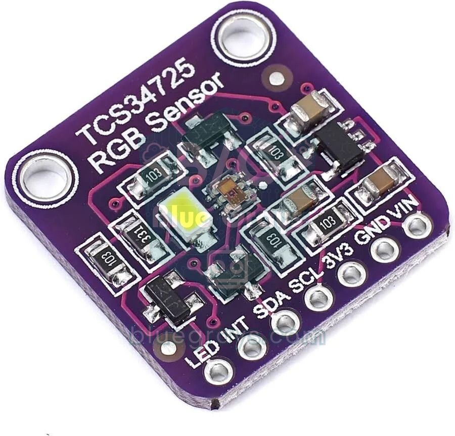
| Feature | TCS3200 | TCS34725 |
|---|---|---|
| Output | Frequency (square wave) | I2C, address 0x29 |
| Signal wires | S0–S3, OUT and OE | SDA and SCL (optional INT and LED) |
| Resolution | Depends on the measuring method and time | 16 bits per channel |
| IR filter | No | Yes (on the chip) |
| Settings | 3 frequency scales and power down | 4 gains, 2.4–614 ms integration time |
| Supply | 2.7–5.5 V | Chip 3.3 V; modules with a regulator 3–5 V |
| Lighting | Usually 4 white LEDs | Usually 1 white LED |
| Processor load | Busy while timing pulses | The chip measures, the Arduino only reads |
| Best for | Learning, simple color sorters | Accurate color, color temperature and lux measurement |
1// TCS34725 ile ham RGBC, renk sıcaklığı ve lüks / Raw RGBC, color temperature and lux with the TCS34725
2#include <Wire.h>
3#include <Adafruit_TCS34725.h>
4
5// 50 ms entegrasyon süresi, 4x kazanç / 50 ms integration time, 4x gain
6Adafruit_TCS34725 tcs = Adafruit_TCS34725(TCS34725_INTEGRATIONTIME_50MS, TCS34725_GAIN_4X);
7
8void setup() {
9  Serial.begin(9600);
10  if (!tcs.begin()) {                                 // 0x29 adresinde ara / look for it at 0x29
11    Serial.println("TCS34725 bulunamadi / not found");
12    while (true) {
13      delay(1000);
14    }
15  }
16}
17
18void loop() {
19  uint16_t r, g, b, c;
20  tcs.getRawData(&r, &g, &b, &c);                     // 16 bit ham değerler / 16-bit raw values
21  uint16_t kelvin = tcs.calculateColorTemperature_dn40(r, g, b, c);
22  uint16_t lux = tcs.calculateLux(r, g, b);
23  Serial.print("R: ");
24  Serial.print(r);
25  Serial.print("  G: ");
26  Serial.print(g);
27  Serial.print("  B: ");
28  Serial.print(b);
29  Serial.print("  C: ");
30  Serial.print(c);
31  Serial.print("  K: ");
32  Serial.print(kelvin);
33  Serial.print("  Lux: ");
34  Serial.println(lux);
35  delay(500);
36}
Before uploading the code, install the Adafruit TCS34725 library from the Library Manager; when it asks about dependencies, choose to install them all. On the Arduino Uno, connect SDA to A4 and SCL to A5; on the ESP32, use GPIO 21 and 22. getRawData() waits for the integration time and returns the raw red, green, blue and clear (C) values; calculateColorTemperature_dn40() gives the color temperature in kelvin, and calculateLux() an approximate light level. The calibration and nearest-color logic apply to this sensor just the same. If you want a sensor that detects hand gestures and proximity as well as color, the APDS-9960 is a good alternative.
Project ideas with the TCS3200
- Color sorting machine: Sort candies, beads or LEGO pieces into separate bins by color.
- Color copying lamp: Recreate the color of the object you hold in front of the sensor with an RGB LED or a WS2812B strip.
- Color reading robot: Teach your line following robot to stop at a red mark on the floor and carry on at a green one.
- Color recognizing robot arm: Use a robot arm to pick up cubes and drop each color into its own bin.
- Talking color detector: Announce the detected color with a pre-recorded sound on a DFPlayer Mini; it makes a handy aid for visually impaired people.
- Water color monitor: Track changes in the color of water in a clear container over time and raise an alert for an aquarium or an irrigation tank.
Common mistakes and how to fix them
| Symptom | Likely cause | Fix |
|---|---|---|
| pulseIn always returns 0 or the timeout value | OE floating or HIGH, S0 and S1 both LOW (power down) or OUT on the wrong pin | Connect OE to GND, set S0 HIGH and S1 LOW, compare the OUT pin with the code |
| Values keep jumping | Room light, a flickering lamp or a changing distance | Shield the sensor with a black tube, fix the distance, average several readings |
| Every object reads as the same color | No calibration; the channels have different sensitivities | Do a white and black calibration, measure the references again |
| Colors drift in daylight | The TCS3200 has no IR filter | Measure inside a closed box or use a TCS34725 |
| Levels stick at 0 or 255 | The object is at a different distance than during calibration | Keep the same distance as during calibration, recalibrate if needed |
| ESP32 or Pico behaves strangely | Module powered from 5 V, OUT outputs 5 V | Power the module from 3V3 or use a level shifter |
| Readings go wrong when the servo moves | Servo current pulls the supply voltage down | Use a separate 5 V supply for the servos and connect the GNDs |
The TCS3200 is a great sensor for learning how light turns into frequency, why calibration matters and how to build a simple classification algorithm. Moving on to the TCS34725 when you need more accuracy is easy too, because the calibration and nearest-color logic you've learned carry over unchanged. In the BlueGrays app you'll find RGB LED color mixing, an ESP32 color mixer lamp, LDR light measurement and servo motor projects with circuit diagrams and step-by-step code, and you can combine the color sensor with them to build your own machine.
Frequently asked questions
How far away can the TCS3200 color sensor detect color?
The most stable results come at about 1–3 cm, because the light from the module's LEDs weakens quickly with distance. More important than the distance itself is keeping it the same for every reading, and you should calibrate at that distance too. This sensor isn't suitable for reading the color of large surfaces far away.
What is the difference between the TCS230 and the TCS3200?
The TCS230 is the same manufacturer's older color sensor, and the TCS3200 is its improved version. Both use an 8×8 photodiode array, a frequency output and the same S0–S3 control logic, so the wiring and code are shared. Most modules sold today carry the TCS3200.
Why does pulseIn return 0 with the TCS3200?
pulseIn returns 0 when it doesn't see a pulse within the given timeout. The most common causes are the OE pin not being connected to GND, S0 and S1 both left LOW (which puts the sensor into power-down mode) and OUT being wired to a different pin than the one in the code. If the area in front of the sensor is completely dark, the frequency drops to a few hertz and no pulse is caught within a short timeout.
Does the TCS3200 work with the ESP32 and Raspberry Pi Pico?
Yes. Since the TCS3200 runs on 2.7–5.5 V, you can power the module from the board's 3V3 pin, so the OUT pin also produces 3.3 V pulses. If you power the module from 5 V, you need a voltage divider or a level shifter on the OUT line. When measuring with MicroPython on the Pico, 2% frequency scaling gives more accurate results.
Which is better, the TCS3200 or the TCS34725?
For accurate color measurement the TCS34725 is better: it has an IR blocking filter, 16-bit resolution per channel and adjustable gain, and it connects with just two I2C wires. The TCS3200 is a common and perfectly adequate choice for learning frequency measurement and calibration and for building simple color sorters.
How many colors can the TCS3200 tell apart?
Under controlled lighting and at a fixed distance, the TCS3200 reliably separates 6–8 clearly different colors such as red, orange, yellow, green, blue, purple, black and white. Telling close shades apart, like light and dark green, is possible too, but it takes more careful calibration, many reference readings for each shade and a tight threshold.
Projects to build after reading this
See all projects
Measuring Light Intensity with an LDR
Want to see how bright your room is as a number? The LDR, a small part that reacts to light, measures the light around it, and the Arduino writes the value to your computer screen every half second. C

Reading Light Intensity with the ESP32 LDR Module
Real-time monitoring of the LDR module's raw ADC value and relative light percentage calculated from dark and light reference values in the Serial Monitor. This percentage is not a lux measurement. Teaches the module’s calibration logic. It is ideal to complete this before Project 10, as it is used to determine the threshold value.
Using an RGB LED
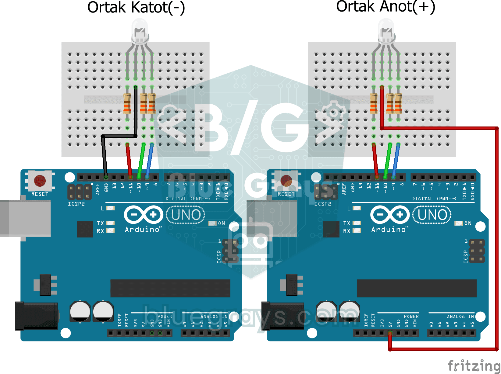
Three colours hide inside a single LED: the RGB LED lights up red, then green, then blue, each colour on for half a second and off for half a second, before the cycle starts again. All you need is one
Smooth Color Transition with RGB Led
A single RGB LED drifts slowly from red to green, green to blue and back to red, looping through the rainbow without ever stopping. Each fade takes about two and a half seconds, and the yellow, turquo

ESP32 Color Mixer Light (3 Potentiometers + RGB LED + OLED)
A smart color-mixing lamp that lets you mix any color you want by turning three potentiometers with the ESP32! As you turn the red, green, and blue potentiometers, the common-cathode RGB LED changes color in real time. The SSD1306 OLED display shows real-time values for each color in the 0–255 range, visual fill bars, and the HEX web color code (such as #FF8040). A mini professional color studio—teaches RGB color theory, ADC analog reading, brightness control via PWM, and I2C display design all

ESP32 RGB LED Control
Unlimited color generation with a single RGB LED instead of 3 separate LEDs. As in Arduino, we make a rainbow transition by setting the R/G/B values with analogWrite(). Color theory (such as red+green=yellow) is seen practically.
Using a Servo Motor
The arm of a small servo motor turns to three positions in turn: all the way to the start, right to the middle and all the way to the end, waiting two seconds at each stop. The Arduino tells the motor

TCRT5000 Black and White Surface Detection
With the little sensor that acts as the eye of line-following robots, you can tell whether the floor is black or white. The TCRT5000 shines invisible light at the floor and checks how much of it bounc