
TT Gear Motor with Arduino: Speed, Torque, PWM and Encoder
What is a DC gear motor (yellow TT motor)? 1:48 ratio, speed and torque, 3–6 V, measuring current, PWM speed matching, noise capacitors, encoder, N20 vs TT.

A DC gear motor is a small, fast DC motor with a gearbox (reducer) added to its shaft to lower the speed and raise the torque. The yellow plastic TT motor you see on Arduino robot cars is the most common member of this family: the motor inside spins thousands of times a minute, but thanks to the gears the wheel turns only 100–250 times a minute and gains enough force to drive a car with ease. It's usually sold as a set with a 65 mm rubber wheel and runs on 3–6 V.
In this guide you'll learn how the gear ratio (1:48) changes speed and torque, the TT motor's voltage, current and speed values, how to measure the current the motor draws and how to choose the right motor driver. Then you'll see why two motors turn at different speeds with the same PWM value, and you'll match them first in software and then by measuring with an encoder disc. You'll also find noise capacitors, ESP32 and Raspberry Pi Pico code, and a comparison with the N20 micro motor.
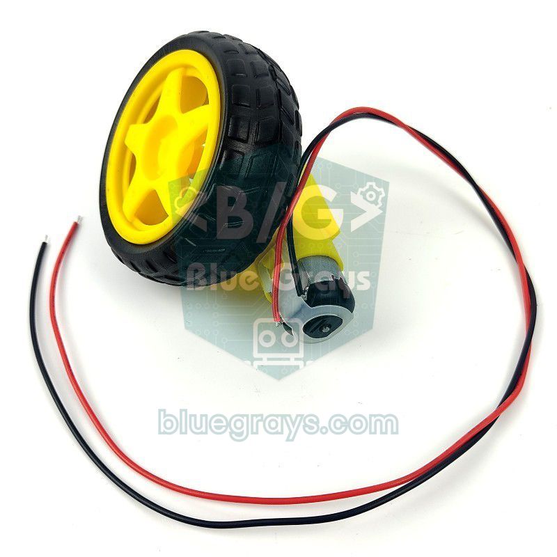
What is a DC gear motor and how does it work?
An ordinary small DC motor spins at 8,000–10,000 rpm with no load, but its torque is very low; fit it directly to a wheel and it won't move the car. The reducer uses meshing gears to cut this high speed and raise the torque by the same ratio. With a 1:48 ratio, the output shaft turns once for every 48 turns of the motor shaft: speed is divided by 48, and torque is multiplied by roughly 48 (minus friction losses in the gears). Power (torque × speed) stays the same; the reducer simply trades speed for force. That's why gear motors are ideal for jobs that need slow but strong motion, such as wheels, winches, doors or conveyors.
| Feature | Yellow TT motor (1:48, typical values) |
|---|---|
| Operating voltage | 3–6 V DC |
| Gear ratio | 1:48 (1:120 and 1:220 versions also exist) |
| No-load output speed | About 90–120 rpm at 3 V, about 200–250 rpm at 6 V |
| No-load current | About 150 mA |
| Stall current | About 1.2 A at 4.5 V, about 1.5 A at 6 V |
| Stall torque | About 0.4 kg·cm at 3 V, about 0.8 kg·cm at 6 V |
| Shaft | Double-sided plastic shaft with two flats |
| Body and gears | Plastic; about 70 × 22 × 18 mm, 30 g |
| Wheel | About 65 mm diameter, rubber |
Gear ratio, speed and torque calculations
A few simple calculations are enough when choosing a motor or estimating how fast a robot will go. A wheel's circumference is π × diameter: for a 65 mm wheel, 3.14 × 6.5 ≈ 20.4 cm. A wheel turning at 200 rpm with no load at 6 V covers 200 × 20.4 = 4080 cm per minute, about 0.68 m/s; under load this drops by 20–30%. On the torque side, 0.8 kg·cm at the wheel's 3.25 cm radius equals a pushing force of 0.8 / 3.25 ≈ 0.25 kg; that's the most the motor can produce before it stalls. Motors shouldn't be loaded with more than about a third of their stall torque for long periods.
| Gear ratio | Output speed (6 V, no load) | Torque | Good for |
|---|---|---|---|
| 1:48 | About 200–250 rpm | Medium | Robot car, line follower, obstacle-avoiding robot |
| 1:120 | About 80–100 rpm | High | Car carrying heavy loads, slow and controlled motion |
| 1:220 | About 45–55 rpm | Very high | Door, curtain, turntable, solar tracker |
What voltage does a TT motor run on?
The TT motor's rated voltage is 3–6 V, and in this range its speed changes almost in proportion to the voltage. The most common power source is 4 AA batteries: new alkaline cells give 6.0–6.4 V, rechargeable Ni-MH cells 4.8–5.2 V. Two 18650 Li-ion cells give 8.4 V when fully charged, which is too much for a 6 V motor; but drivers such as the L298N drop about 2 V, so around 6 V reaches the motor. If you use a more efficient driver, you can cap the maximum PWM value: to get an average of 6 V from 8.4 V, use at most 255 × 6 / 8.4 ≈ 182. Battery details are in the running an Arduino on batteries and mAh battery capacity articles.
Measuring the current the motor draws
Knowing the current lets you choose the right driver and work out how long the battery will last. The easiest way is to set a multimeter to current and connect it in series with the motor: plug the red probe into the 10A jack, disconnect the wire coming from the battery's positive and put the multimeter in between. Measure first with the motor in the air (no load), then with the robot on the floor, and finally by holding the wheel with your hand for a brief moment. For using a multimeter see how to use a multimeter, and to monitor current continuously with an Arduino see the ACS712 current sensor article.
| Situation | Typical current (6 V) | What does it mean? |
|---|---|---|
| Wheel in the air, no load | 150–170 mA | Gear and brush friction; the motor is healthy |
| Robot driving on a flat floor | 200–350 mA | Normal operation; use this value for battery calculations |
| Ramp or carpet | 400–700 mA | The motor is struggling; consider a 1:120 ratio or a lighter chassis |
| Wheel blocked (stall) | 1.2–1.5 A | Worst case for the driver and battery; the motor heats up if it lasts |
| Moment of start-up | Briefly up to 1 A | Can pull the battery voltage down and reset the Arduino |
Battery life follows easily from these values: a robot whose two motors draw 0.6 A in total on a flat floor will run for roughly 2000 / 600 ≈ 3.3 hours on 2000 mAh Ni-MH AA cells. For choosing a driver, look at the stall current: the L9110S supplies about 800 mA per channel, which is borderline for TT motors; the TB6612FNG, with 1.2 A continuous and 3.2 A peak per channel, has more headroom. To calculate the relationship between current, voltage and resistance quickly you can use the Ohm's law calculator.
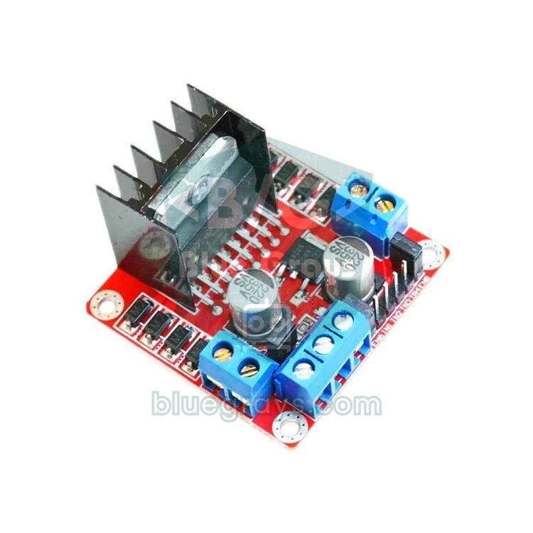
Choosing a motor driver and wiring
| Driver | Current per channel | Voltage drop | Note |
|---|---|---|---|
| L298N | 2 A | About 1.5–2.5 V | Rugged and common; with 4×AA about 4–4.5 V is left for the motor |
| L293D (shield) | 0.6 A (peak 1.2 A) | About 1.5–2.5 V | Plugs onto the Uno, drives four motors; borderline for TT |
| L9110S | 0.8 A | Low | Small and cheap; struggles at stall current |
| TB6612FNG | 1.2 A (peak 3.2 A) | Very low (MOSFET) | Uses the battery voltage efficiently, one of the best choices for TT |
| Connection | Arduino Uno | ESP32 | Raspberry Pi Pico |
|---|---|---|---|
| L298N ENA (left motor speed, PWM) | D5 | GPIO 25 | GP15 |
| L298N IN1 / IN2 | D7 / D8 | GPIO 27 / GPIO 33 | GP14 / GP13 |
| L298N ENB (right motor speed, PWM) | D6 | GPIO 26 | GP10 |
| L298N IN3 / IN4 | D9 / D4 | GPIO 32 / GPIO 4 | GP12 / GP11 |
| Left / right encoder (LM393) output | D2 / D3 | GPIO 34 / GPIO 35 | GP16 / GP17 |
| Encoder module VCC | 5V | 3V3 | 3V3(OUT) |
| GND | Battery negative, L298N and Arduino GND shared | Shared | Shared |
Don't forget to remove the ENA and ENB jumpers; if they stay on, the motor ignores PWM and always runs at full speed. All the L298N's pins and its brake and coast behaviour are explained in detail in the DC motor and L298N article. If a motor turns the wrong way, swapping that motor's two wires at the driver is the cleanest fix rather than changing the code.
Arduino code: forward, reverse, turning and speed trim
1// İki TT motoru L298N ile: ileri, geri, dönüş ve hız dengeleme
2// Two TT motors with an L298N: forward, reverse, turning and speed trim
3const byte ENA = 5, IN1 = 7, IN2 = 8;    // sol motor / left motor
4const byte ENB = 6, IN3 = 9, IN4 = 4;    // sağ motor / right motor
5const int MIN_PWM = 70;                  // altında motor kalkamaz / below this the motor won't start
6const float SOL_KATSAYI = 1.00;          // hızlı motoru yavaşlatmak için / to slow the faster motor
7const float SAG_KATSAYI = 0.92;
8
9void motorSur(byte en, byte inA, byte inB, int hiz, float katsayi) {   // hiz: -255..255
10  int pwm = abs(hiz) * katsayi;
11  if (pwm > 0 && pwm < MIN_PWM) pwm = MIN_PWM;    // ölü bölgeyi atla / skip the dead zone
12  digitalWrite(inA, hiz > 0 ? HIGH : LOW);
13  digitalWrite(inB, hiz < 0 ? HIGH : LOW);
14  analogWrite(en, hiz == 0 ? 0 : pwm);
15}
16
17void sur(int sol, int sag) {
18  motorSur(ENA, IN1, IN2, sol, SOL_KATSAYI);
19  motorSur(ENB, IN3, IN4, sag, SAG_KATSAYI);
20}
21
22void setup() {
23  byte pinler[] = {ENA, IN1, IN2, ENB, IN3, IN4};
24  for (byte p : pinler) pinMode(p, OUTPUT);
25}
26
27void loop() {
28  sur(200, 200);    // ileri / forward
29  delay(2000);
30  sur(0, 0);        // dur / stop
31  delay(500);
32  sur(-180, -180);  // geri / reverse
33  delay(1500);
34  sur(0, 0);
35  delay(500);
36  sur(180, -180);   // yerinde sağa dön / spin right in place
37  delay(600);
38  sur(0, 0);
39  delay(1500);
40}
MIN_PWM in the code is the smallest PWM value at which the motor overcomes static friction and starts to turn. The Uno's pins 5 and 6 produce PWM at about 980 Hz; TT motors usually just hum without turning below a value somewhere between 60 and 90. Finding this value for your own motor is easy: start the PWM at 0, raise it in steps of five and note the value at which the wheel first turns. For how PWM works and details about its frequency, see What is PWM?.
Why do two motors turn at different speeds?
When you give the same PWM to two TT motors from the same box you expect the robot to go straight, but more often than not the car drifts to one side. The reason is manufacturing variation in cheap motors: the tolerance of the brushes and magnets, gear friction, lubrication and the alignment of the plastic shafts are slightly different on every motor. The ±10% tolerance sellers quote can mean a speed difference of up to 20% between two motors. On top of that, the difference isn't constant: it changes as the battery voltage drops, as the motor warms up or as the floor changes. And because the motors are mounted mirrored, one turns forward while the other turns backward from the motor's point of view, and some motors run at different speeds in the two directions.
- Drive the robot forward on a flat floor for 2–3 metres at the same PWM and note which way it drifts.
- If the car drifts right, the left motor is faster; lower SOL_KATSAYI to 0.95 and try again.
- Change the factor in steps of 0.01–0.02 until the car goes straight; this usually takes 3–5 tries.
- Run the same test in reverse; if the difference is large, use separate factors for forward and reverse.
- The setting may drift when the battery voltage changes; for a permanent, self-correcting solution move on to the encoder method below.
Killing noise: motor capacitors
As brushed DC motors spin, small sparks form between the brushes and the commutator. These sparks cause voltage spikes on the supply line and electrical noise radiated into the air. The symptoms are familiar: the Arduino resets by itself when the motor runs, garbage appears in the Serial Monitor, the ultrasonic sensor measures nonsense distances or the Bluetooth connection drops. The fix is to suppress the noise at its source, right on the motor.
- 100 nF across the motor terminals: Solder a 100 nF ceramic capacitor marked 104 between the two terminals of each motor. Keep its legs as short as possible.
- Two more to the case: On motors with a metal case, adding a 100 nF from each terminal to the case reduces noise further. The TT motor's case is plastic, so the single capacitor across the terminals is usually enough.
- Electrolytic on the driver supply: Put a 470–1000 µF electrolytic capacitor on the L298N's supply input; it softens the dip in battery voltage at start-up.
- Twist the wires: Twist the motor's two wires around each other; the noise radiated by the wires drops.
- Separate the supplies: If possible, power the Arduino and the motors from separate batteries and join the GNDs at a single point.
You'll find how capacitors work and how to read their codes in What is a capacitor?, and other causes of resets when the motor runs in Arduino keeps resetting.
Measuring speed with an encoder disc
The TT motor's shaft comes out on both sides; on the end that doesn't carry the wheel you usually fit the 20-slot plastic encoder disc that comes with the set. The disc's slots pass between the arms of a U-shaped infrared slot sensor (an optical module with an LM393 comparator), and each slot produces a pulse. Because the disc turns at the same speed as the wheel, 20 pulses mean one wheel revolution. If 30 pulses are counted in half a second, the wheel has turned 30 / 20 = 1.5 times, which means 1.5 × 120 = 180 rpm. Multiplying the number of turns by the wheel circumference also gives the distance travelled: each pulse is about 20.4 / 20 ≈ 1 cm.
The code below measures the speed of both wheels and adjusts the right motor's PWM automatically until both sides count the same number of pulses. This is a simple proportional (P) controller: the bigger the difference, the bigger the correction. Because slot sensors can produce several pulses as an edge passes, the interrupt function ignores pulses closer together than 2 ms. For interrupt details see the Arduino interrupt article.
1// 20 yarıklı enkoder diskiyle devir ölçümü ve iki motoru eşitleme
2// RPM measurement with 20-slot encoder discs and matching two motors
3const byte ENA = 5, IN1 = 7, IN2 = 8;      // sol motor / left motor
4const byte ENB = 6, IN3 = 9, IN4 = 4;      // sağ motor / right motor
5const byte ENC_SOL = 2, ENC_SAG = 3;       // LM393 yarık sensörleri / slot sensors
6const byte YARIK = 20;                     // disk başına yarık / slots per disc
7const int TEMEL_PWM = 180;                 // sol motorun sabit hızı / fixed left speed
8const float KP = 4.0;                      // oransal kazanç / proportional gain
9
10volatile unsigned int solSayac = 0, sagSayac = 0;
11volatile unsigned long solSon = 0, sagSon = 0;
12int sagPwm = TEMEL_PWM;
13unsigned long oncekiZaman = 0;
14
15void solDarbe() {
16  unsigned long t = micros();
17  if (t - solSon > 2000) {                 // 2 ms'den yakın darbeleri yok say / ignore bounces
18    solSayac++;
19    solSon = t;
20  }
21}
22
23void sagDarbe() {
24  unsigned long t = micros();
25  if (t - sagSon > 2000) {
26    sagSayac++;
27    sagSon = t;
28  }
29}
30
31void setup() {
32  Serial.begin(9600);
33  byte pinler[] = {ENA, IN1, IN2, ENB, IN3, IN4};
34  for (byte p : pinler) pinMode(p, OUTPUT);
35  pinMode(ENC_SOL, INPUT);
36  pinMode(ENC_SAG, INPUT);
37  attachInterrupt(digitalPinToInterrupt(ENC_SOL), solDarbe, RISING);
38  attachInterrupt(digitalPinToInterrupt(ENC_SAG), sagDarbe, RISING);
39  digitalWrite(IN1, HIGH); digitalWrite(IN2, LOW);   // iki motor da ileri / both forward
40  digitalWrite(IN3, HIGH); digitalWrite(IN4, LOW);
41  analogWrite(ENA, TEMEL_PWM);
42  analogWrite(ENB, sagPwm);
43}
44
45void loop() {
46  if (millis() - oncekiZaman >= 500) {     // yarım saniyede bir / every half second
47    oncekiZaman = millis();
48    noInterrupts();
49    unsigned int sol = solSayac, sag = sagSayac;
50    solSayac = 0;
51    sagSayac = 0;
52    interrupts();
53
54    float solDevir = sol * 120.0 / YARIK;  // 0,5 s'deki darbe -> d/dk / pulses in 0.5 s -> rpm
55    float sagDevir = sag * 120.0 / YARIK;
56    sagPwm += (int)(KP * ((int)sol - (int)sag));    // sağ geride kaldıysa hızlandır / speed up if behind
57    sagPwm = constrain(sagPwm, 70, 255);
58    analogWrite(ENB, sagPwm);
59
60    Serial.print(F("Sol / Left: "));
61    Serial.print(solDevir, 0);
62    Serial.print(F(" d/dk  Sag / Right: "));
63    Serial.print(sagDevir, 0);
64    Serial.print(F(" d/dk  Sag PWM: "));
65    Serial.println(sagPwm);
66  }
67}
When you run the code you'll see in the Serial Monitor that the right PWM value changes during the first few seconds, then the two wheel speeds converge. If KP is too large the right motor oscillates, speeding up and slowing down; if it's too small the correction is sluggish; trying values between 2 and 6 is a good start. For more precise driving you can also match the total distance or write a full PID controller. The encoder sensor works much like the infrared sensors used in line-following robots; details in the TCRT5000 infrared sensor article.
Controlling a TT motor with an ESP32
The ESP32's 3.3 V pins drive the inputs of the L298N and TB6612FNG without problems, because these drivers treat anything above 2.3 V as HIGH. The ESP32 Arduino core supports analogWrite; the default PWM frequency is about 1 kHz. Power the encoder sensors from 3V3 so their outputs are 3.3 V too; GPIO 34 and 35 are input-only pins and ideal for the encoders. Thanks to the ESP32's Wi-Fi and Bluetooth you can control the robot from your phone and show the speed on a web page.
1// ESP32: iki TT motor, enkoderle devir ölçümü / two TT motors with RPM measurement
2const int ENA = 25, IN1 = 27, IN2 = 33;      // sol motor / left motor
3const int ENB = 26, IN3 = 32, IN4 = 4;       // sağ motor / right motor
4const int ENC_SOL = 34, ENC_SAG = 35;        // yalnız giriş pinleri / input-only pins
5const int YARIK = 20;
6
7volatile uint32_t solSayac = 0, sagSayac = 0;
8portMUX_TYPE kilit = portMUX_INITIALIZER_UNLOCKED;
9
10void IRAM_ATTR solDarbe() {
11  portENTER_CRITICAL_ISR(&kilit);
12  solSayac++;
13  portEXIT_CRITICAL_ISR(&kilit);
14}
15
16void IRAM_ATTR sagDarbe() {
17  portENTER_CRITICAL_ISR(&kilit);
18  sagSayac++;
19  portEXIT_CRITICAL_ISR(&kilit);
20}
21
22void sur(int sol, int sag) {                 // -255..255
23  digitalWrite(IN1, sol > 0); digitalWrite(IN2, sol < 0);
24  digitalWrite(IN3, sag > 0); digitalWrite(IN4, sag < 0);
25  analogWrite(ENA, abs(sol));
26  analogWrite(ENB, abs(sag));
27}
28
29void setup() {
30  Serial.begin(115200);
31  int pinler[] = {ENA, IN1, IN2, ENB, IN3, IN4};
32  for (int p : pinler) pinMode(p, OUTPUT);
33  pinMode(ENC_SOL, INPUT);
34  pinMode(ENC_SAG, INPUT);
35  attachInterrupt(digitalPinToInterrupt(ENC_SOL), solDarbe, RISING);
36  attachInterrupt(digitalPinToInterrupt(ENC_SAG), sagDarbe, RISING);
37  sur(180, 180);                             // ileri / forward
38}
39
40void loop() {
41  delay(1000);
42  portENTER_CRITICAL(&kilit);
43  uint32_t sol = solSayac, sag = sagSayac;
44  solSayac = 0;
45  sagSayac = 0;
46  portEXIT_CRITICAL(&kilit);
47  Serial.printf("Sol / Left: %.0f d/dk  Sag / Right: %.0f d/dk\n",
48                sol * 60.0 / YARIK, sag * 60.0 / YARIK);   // 1 s'deki darbe -> d/dk / pulses in 1 s -> rpm
49}
TT motor with the Raspberry Pi Pico and MicroPython
Every GPIO on the Pico can generate PWM. In MicroPython you set the PWM object's frequency to 1 kHz and give the speed with duty_u16() in the 0–65535 range; 65535 means full speed. The code below runs the left motor at different speeds and measures its speed with the encoder. If you want to power the Pico from the same battery as the motors, you can connect the L298N's 5V output to the VSYS pin.
1from machine import Pin, PWM
2import machine
3import time
4
5ena = PWM(Pin(15))                     # sol motor hızı / left motor speed
6ena.freq(1000)
7in1 = Pin(14, Pin.OUT)
8in2 = Pin(13, Pin.OUT)
9YARIK = 20
10sayac = 0
11
12def darbe(pin):                        # enkoder kesmesi / encoder interrupt
13    global sayac
14    sayac += 1
15
16enc = Pin(16, Pin.IN)
17enc.irq(trigger=Pin.IRQ_RISING, handler=darbe)
18
19def motor(hiz):                        # hiz: -100..100 (%)
20    in1.value(1 if hiz > 0 else 0)
21    in2.value(1 if hiz < 0 else 0)
22    ena.duty_u16(int(abs(hiz) * 65535 / 100))
23
24for hiz in (40, 60, 80, 100):
25    motor(hiz)
26    time.sleep(1)                      # hızlanmayı bekle / let it settle
27    durum = machine.disable_irq()
28    sayac = 0
29    machine.enable_irq(durum)
30    time.sleep(1)                      # 1 saniye say / count for 1 second
31    print("PWM %{}: {} d/dk".format(hiz, sayac * 60 // YARIK))
32motor(0)
TT motor or N20 micro motor?
| Feature | TT motor (yellow) | N20 micro motor |
|---|---|---|
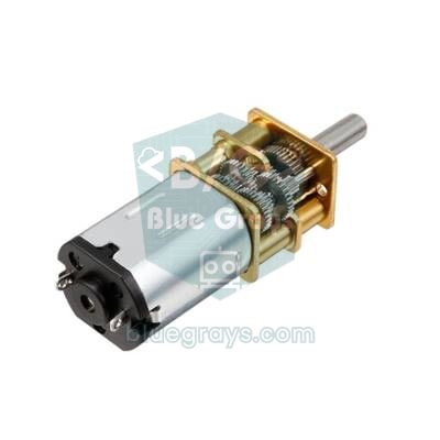
| Size | About 70 × 22 × 18 mm | About 12 × 10 mm cross-section, 25–35 mm long |
| Gears | Plastic | Metal |
| Voltage options | 3–6 V | 3 V, 6 V and 12 V versions |
| Gear ratio | Usually 1:48 (1:120, 1:220) | Wide choice from 1:10 to 1:1000 |
| Shaft | Plastic, with two flats | 3 mm metal D shaft |
| Encoder | Separate disc and slot sensor | Versions with a magnetic Hall encoder fitted at the back are common |
| Price and durability | Very cheap, gears wear over time | More expensive, more precise and longer-lasting |
| Suitable projects | Educational robots, robot car kits | Mini sumo, fast line followers, small mechanisms |
In short, the TT motor is the best start for a first robot car and school projects because it's cheap and easy to mount. If you need a smaller, more precise and durable mechanism, or you're building a competition robot, the N20 is preferred; N20s with encoders measure on the motor shaft, giving hundreds of pulses per wheel revolution and far more precise speed measurement. For an overview of which motor type suits which job, see the DC, servo and stepper motor differences article.
Project ideas with a gear motor
- Robot car: Build a Bluetooth-controlled car with two TT motors, a caster wheel and an L298N; every step is in the Arduino robot car article.
- Line-following robot: Follow a black line with infrared sensors; motor speed balance matters a lot here. See line-following robot.
- Obstacle-avoiding robot: Detect obstacles ahead with an HC-SR04 and change direction; setup in the obstacle-avoiding robot article.
- Measuring wheel: Roll an encoder wheel along the floor to make a digital tape measure for rooms; each pulse is about 1 cm.
- Automatic curtain: Open the curtain in the morning and close it in the evening with a 1:220 TT motor; trigger it by light with an LDR.
- Rotating display stand: Build a stand that slowly turns a small product or model with a slow motor.
Common mistakes and how to fix them
| Symptom | Likely cause | Fix |
|---|---|---|
| Motor hums but doesn't turn | PWM below the dead zone or a weak battery | Raise MIN_PWM, measure the battery voltage |
| Motor always at full speed | ENA/ENB jumper fitted or a non-PWM pin | Remove the jumper; use pins 3, 5, 6, 9, 10, 11 on the Uno |
| Car doesn't go straight | Manufacturing difference between the motors | Balance with a factor or build a closed loop with encoders |
| Arduino resets when the motor runs | Start-up current pulls the battery voltage down, brush noise | Add 100 nF across the motor terminals and 470 µF at the driver input; power the Arduino separately |
| One wheel turns backwards | Motor wires connected the wrong way | Swap that motor's two wires at the driver |
| Speed lower than expected | 2 V lost across the L298N | Use a higher-voltage battery or a MOSFET driver such as the TB6612FNG |
| Encoder counts too many pulses | Sensor chatter at the slot edge | Use a 2 ms dead-time filter in the interrupt, centre the disc in the sensor |
The TT gear motor is a cheap but very instructive part for learning the trade-off between speed and torque in a gear ratio, speed control with PWM and feedback with an encoder. With the right driver, a few capacitors and simple balancing code, your robot drives straight and reliably. In the BlueGrays app you'll find the Bluetooth-controlled car, the obstacle-avoiding robot and infrared sensor projects with step-by-step circuit diagrams and code, so you can turn these motors into a project right away.
Frequently asked questions
What is a DC gear motor?
A DC gear motor is a small high-speed DC motor with a gearbox fitted to its shaft. The gears lower the speed and raise the torque by the same ratio; at 1:48 the output shaft turns once for every 48 turns of the motor shaft. This lets a small motor move a robot car or a mechanism with ease.
What voltage does a TT motor run on?
Yellow TT motors run on 3–6 V, and the most common supply is 4 AA batteries. They turn at about 90–120 rpm at 3 V and about 200–250 rpm at 6 V. A voltage above 6 V makes the motor faster but causes it to heat up and its gears to wear quickly.
How much current does a TT motor draw?
About 150 mA with no load and 200–350 mA in a robot driving on a flat floor. When the wheel is blocked, the current can rise to 1.5 A at 6 V. That's why the motor driver and battery must be chosen for the stall current, and the motor must never be powered directly from an Arduino pin.
Why don't two DC motors turn at the same speed?
Cheap motors differ in their brushes, magnets, gear friction and lubrication; even at the same PWM their speeds can differ by 10–20%. Battery voltage and temperature also change the difference. Applying a factor to the faster motor in software, or measuring both wheel speeds with encoders and adjusting the PWM automatically, solves the problem.
Why is a capacitor fitted to a DC motor?
As brushed motors spin, small sparks at the brushes produce electrical noise. This noise can reset the Arduino, make sensors misread and drop wireless connections. A 100 nF ceramic capacitor soldered across the motor terminals suppresses the noise at its source.
How do you measure motor speed with an encoder disc?
A slotted disc fitted to the motor shaft passes through an optical slot sensor, and each slot produces a pulse. The Arduino counts these pulses with an interrupt; with a 20-slot disc, 20 pulses are one wheel revolution. Divide the number of pulses in one second by 20 and multiply by 60 to get revolutions per minute.
Projects to build after reading this
See all projects
Bluetooth Controlled Car with L298N
Turn your phone into a remote and drive your own robot car. The Arduino receives commands from a remote-control app on your phone through a Bluetooth module and spins the wheels with a motor driver…

Obstacle Avoidance Robot
How about building a smart vehicle that finds its own way? The Obstacle Avoidance Robot constantly scans its surroundings thanks to the ultrasonic sensor in front of it.

TCRT5000 Black and White Surface Detection
With the little sensor that acts as the eye of line-following robots, you can tell whether the floor is black or white.

Reading Reflection (Proximity) with TCRT5000
With a small sensor that sends out invisible light and measures how much bounces back, you can detect the surface in front of it.
Servo Control with Joystick
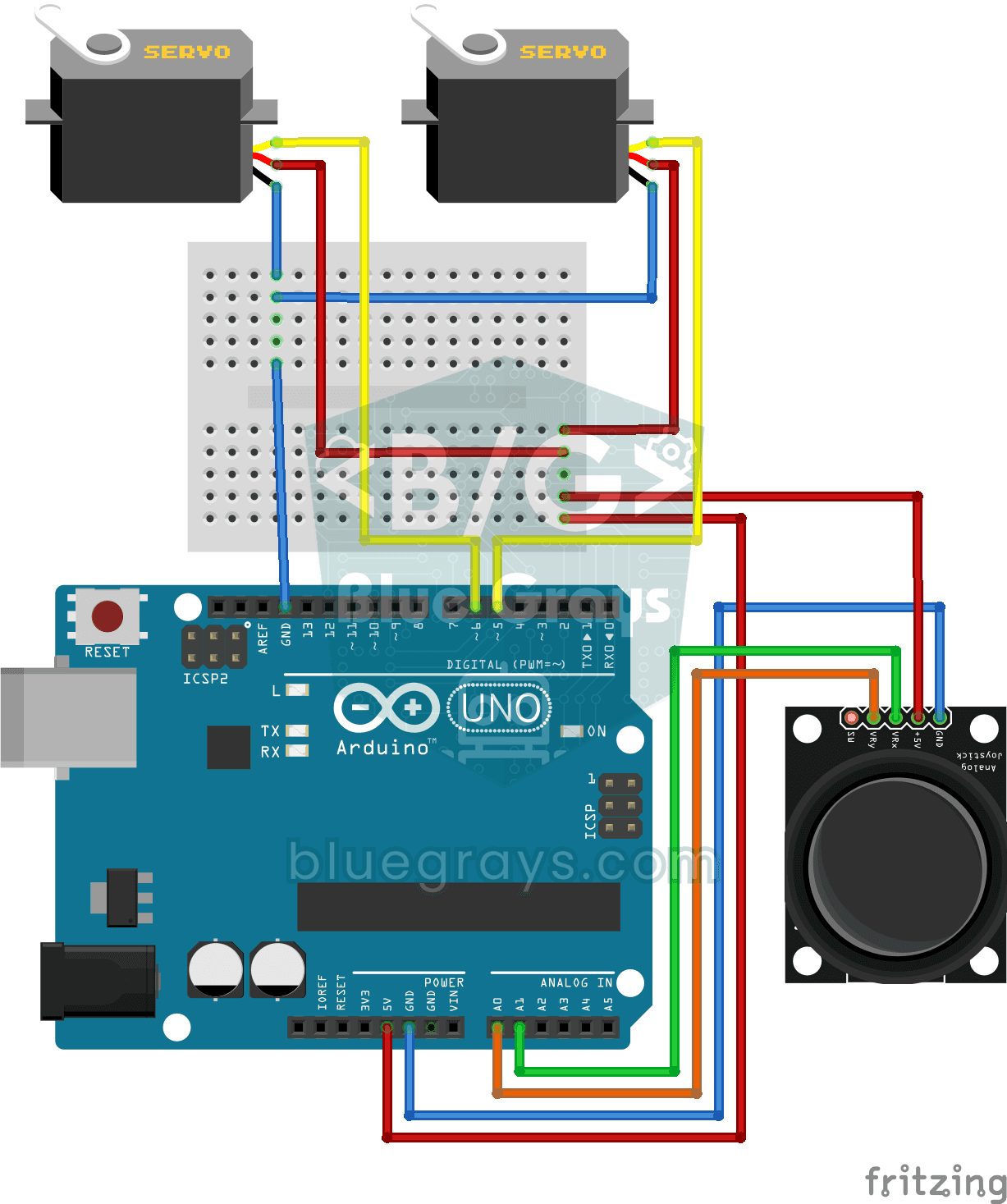
Steer two motors with a joystick, just like turning a security camera. Push the stick left or right and the bottom servo motor slowly turns, push it up or down and the top servo tilts up and down…

ESP32 LED Brightness Control with a Potentiometer (Analog → PWM)
In this project, we control the brightness of an LED analogically using a potentiometer. The ESP32's ADC pin reads the 0-3.3V voltage from the potentiometer, and this value is then converted into a PWM (Pulse Width Modulation) signal and sent to the LED. As a result, as you turn the potentiometer, the LED gradually brightens and dims. With Arduino Core 3.0+, analogWrite() can be used directly; on the ESP32-S2/S3, the ADC resolution is fixed at 12-bit.

ESP32 LED Fade with PWM
Smoothly changing the brightness of the LED from 0 to max, from max to 0. We control PWM with analogWrite() as in Arduino - the same syntax as ESP32 Arduino Core 3.0+ works without problems. Pin definition + pinMode + analogWrite is enough.
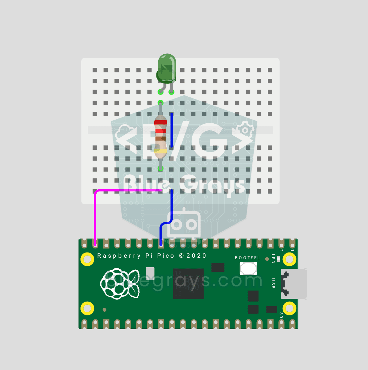
Raspberry Pi Pico PWM LED Fade (Breathing Effect)
The LED doesn't just blink anymore, it breathes! With the Raspberry Pi Pico's PWM (Pulse Width Modulation), the LED's brightness slowly rises and then slowly fades, a calm "breathing" effect like a sleeping laptop's light. You'll learn the machine.PWM class, the 16-bit brightness value from 0–65535 with duty_u16() and the PWM frequency.