
DC Motor vs Servo vs Stepper Motor: Differences and How to Choose
DC motor vs servo vs stepper motor: speed, torque and precision compared, L298N, ULN2003 and A4988 drivers, current draw, BLDC and ESC, and which to use where.
The difference between a DC motor, a servo motor and a stepper motor fits in one sentence: a DC motor spins continuously and fast as long as you power it, a servo moves to the angle you ask for and holds it, and a stepper motor turns in small, countable steps. So if you need to spin a wheel, you pick a DC motor; to open a lid by 90 degrees, a servo; to move a part with a tenth-of-a-millimetre precision, a stepper. Whenever something has to move in an Arduino, ESP32 or Raspberry Pi Pico project, you'll run into one of these three.
In this guide we compare what's inside each motor, real numbers for speed, torque and position accuracy from popular models (TT motor, SG90, MG996R, 28BYJ-48, NEMA 17), which driver each one needs (L298N, a PWM signal, ULN2003, A4988), how much current they draw and which one is used in which project. At the end you'll find Arduino, ESP32 and Pico code that drives all three at once, a short introduction to brushless motors (BLDC) and ESCs, and the most common mistakes.
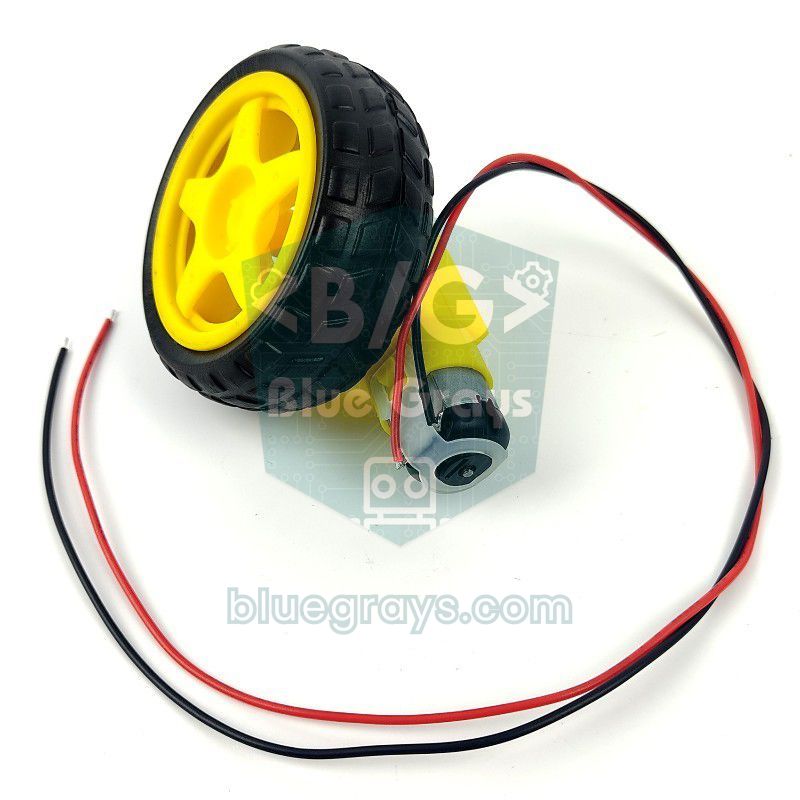
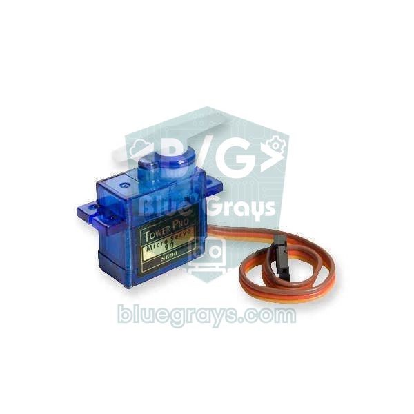
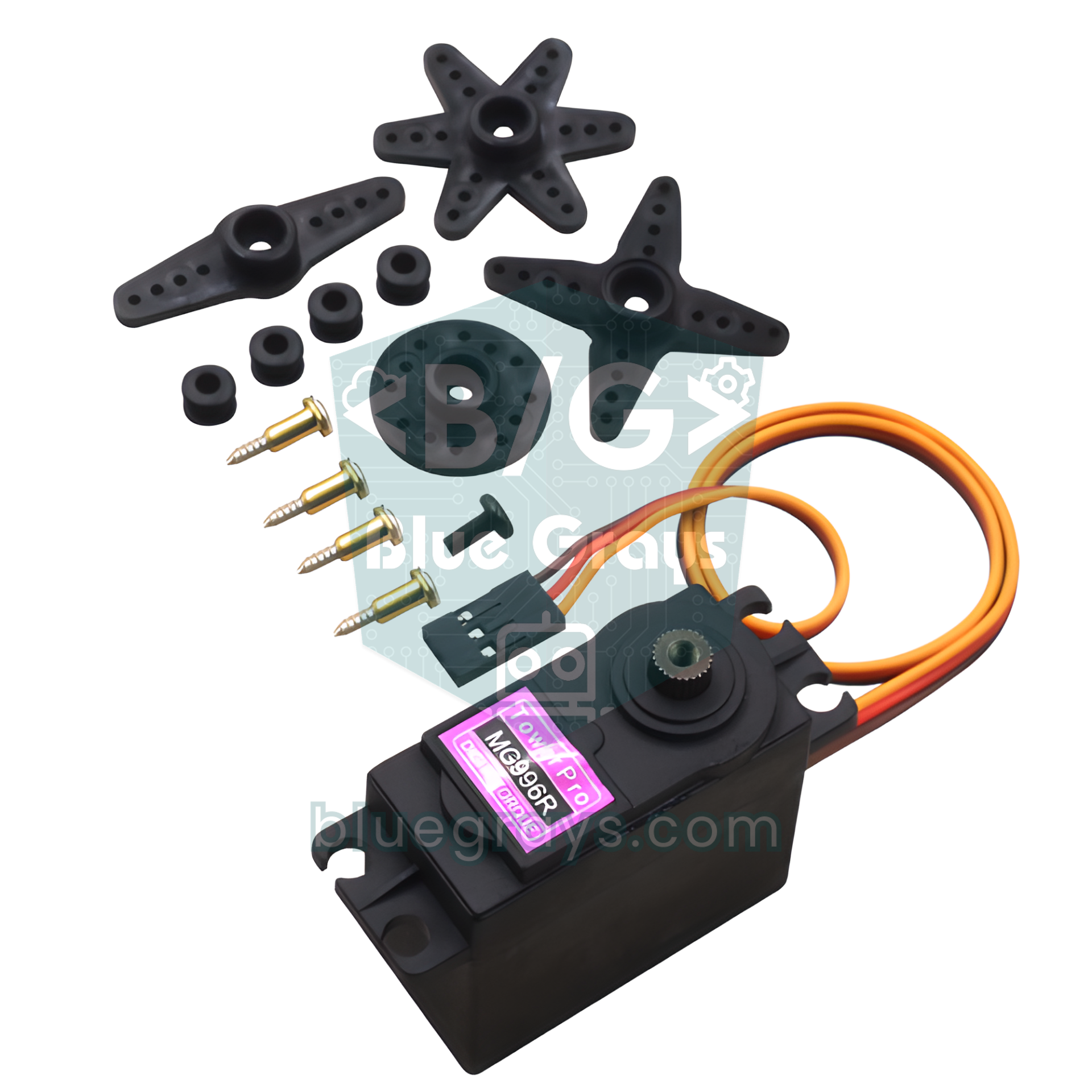
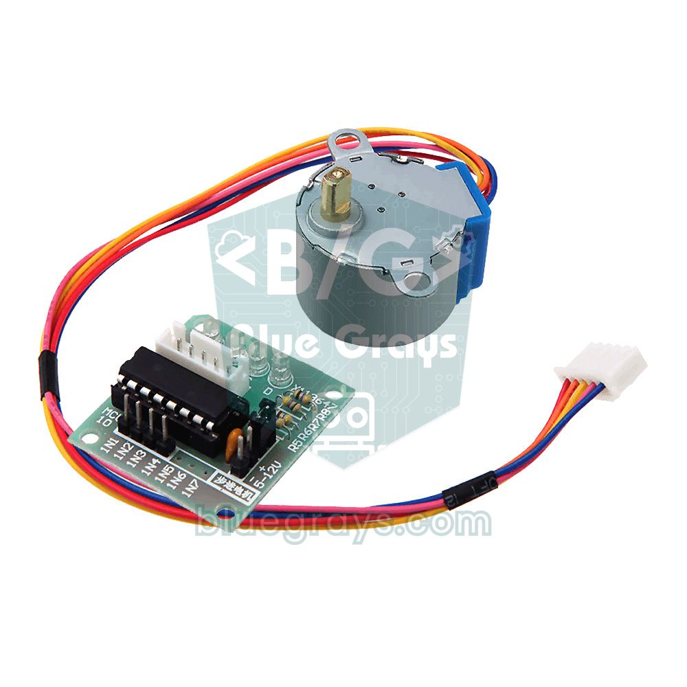
Short answer: the three motors compared in one table
| Feature | DC motor | Servo motor | Stepper motor |
|---|---|---|---|
| Motion | Spins continuously | Moves to a set angle and holds it (usually 0–180°) | Turns step by step, no turn limit |
| What you control | Speed and direction | Angle (position) | Number of steps and step rate |
| Feedback | None (added with an encoder) | Yes: the built-in potentiometer | None (open loop) |
| Speed | Very high (thousands of RPM without a gearbox) | Medium (SG90: 0.1 s/60°) | Low to medium, torque drops as speed rises |
| Torque | Depends on the gearbox | High for its size (thanks to the gearbox) | High at low speed, also holds when stopped |
| Position accuracy | None | About 1° | 1.8° (much finer with microstepping) |
| When stopped | Runs free | Actively holds its position | Locked as long as the coils are powered |
| Driver | H-bridge (L298N, L9110S) or MOSFET | Not needed, signal straight from a pin | ULN2003 or A4988, DRV8825 |
| Wires | 2 | 3 (GND, +, signal) | 4 or 5 (sometimes 6) |
| Typical use | Wheels, fans, pumps | Robot arms, door latches, radar | 3D printers, CNC, camera sliders |
The most important row in the table is feedback. A servo knows where it is thanks to its internal potentiometer, and when something pushes it, it returns to its position. A stepper doesn't know where it is; you simply count how many steps it has taken, and that count is correct as long as the motor isn't overloaded and doesn't skip steps. A DC motor has no idea how far it has turned; if you need position, you have to add an encoder to its shaft. Which motor you choose depends largely on whether your project needs this information.
How does a DC motor work?
Almost every DC motor in hobby projects is a brushed DC motor. Inside are fixed magnets and a rotating coil (the rotor); carbon brushes and a copper commutator flip the current direction as the rotor turns, so it keeps spinning. It has two wires: apply voltage and it turns, swap the wires and it turns the other way. The voltage sets the speed and the current it draws sets the torque. While the motor spins, the coils generate a counter-voltage called back EMF that limits the current; when the shaft is blocked, that back EMF disappears and the current jumps to the stall current.
A small DC motor without a gearbox spins at thousands of RPM but has very little torque, which is why robots always use geared motors. The 1:48 gearbox in a TT motor drops roughly 12,000 RPM at the motor shaft to 250 RPM at the wheel while multiplying the torque by about 48 (minus gear losses). You change speed with PWM and direction with an H-bridge; the details are in DC Motor Control with the L298N. The weak point of a DC motor is position: the same PWM value gives a different speed depending on battery voltage and load, so a "drive forward for 2 seconds" command covers a different distance every time. If you need exact distance, you add an encoder to the wheel.
How does a servo motor work?
A servo motor is really a complete system packed into a small box: a DC motor, a gear train that lowers the speed and raises the torque, a potentiometer attached to the output shaft, and a control board. The Arduino doesn't send the servo an angle directly but a pulse at 50 Hz (once every 20 ms); the width of the pulse describes the desired position. The control board compares that target with the actual position read from the potentiometer and drives the motor in that direction until the difference is zero. This is called closed-loop control, and it's why a servo resists when you try to turn it by hand.
| Device | What the pulse width means | Example |
|---|---|---|
| Standard servo (180°) | Angle: about 1 ms one end, 1.5 ms centre, 2 ms the other end | SG90, MG90S, MG996R |
| Continuous rotation servo (360°) | Speed and direction: 1.5 ms stop, shorter one way, longer the other way | FS90R |
| ESC + brushless motor | Throttle: 1 ms stop, 2 ms full throttle | Drone and RC model ESCs |
The standard RC range is 1–2 ms, but most cheap servos like the SG90 need roughly 0.5–2.4 ms for the full 180°, and the Arduino Servo library uses 544–2400 µs by default. The SG90's dead band, the smallest change it reacts to, is about 10 µs, which works out to roughly 1°; that's why the practical precision of a servo is around one degree. A continuous rotation servo (FS90R) is a servo with its feedback disabled: you control speed and direction instead of angle, and position information is lost. If you need more power, the metal-gear MG996R is the standard choice; for the basics, see What Is a Servo Motor?
How does a stepper motor work?
A stepper motor has no brushes. The coils in the housing are energised in a set order, and the magnetic rotor takes a single step towards the next coil each time. The most common hybrid steppers have 200 steps per revolution, or 1.8° per step. Send a number of pulses and it takes that many steps; send them faster and it turns faster. As long as the coils are powered, the motor stays locked in place; this is called holding torque. The key difference: a stepper is open loop. If the load exceeds its torque it skips steps, and the Arduino never notices. That's why 3D printers drive every axis to a limit switch at startup (homing).
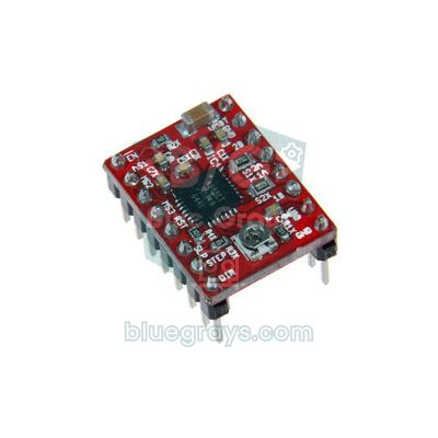
You'll come across two types of stepper. Unipolar motors (28BYJ-48, 5 wires) have a common wire shared by the coils and are driven by a simple transistor array such as the ULN2003. Bipolar motors (NEMA 17, 4 wires) need the coil current to be reversed, which is done by current-limiting drivers such as the A4988, DRV8825 or TMC2209. These drivers also do microstepping: the A4988 splits each full step into 16, raising the number of steps per turn to 3200 and making the motion much quieter and smoother. For details, see 28BYJ-48 and ULN2003 and A4988 stepper motor driver.
Speed, torque and position accuracy: the numbers
| Model | Supply | Speed | Torque | Precision | Current |
|---|---|---|---|---|---|
| TT DC motor (1:48) | 3–6 V | ≈ 200–250 RPM (6 V, no load) | 0.8 kg·cm (6 V, stall) | None (needs an encoder) | 150 mA idle, 1.5 A stalled |
| SG90 servo | 4.8–6 V | 0.1 s / 60° | 1.8 kg·cm | ≈ 1° | Very little when idle, can exceed 0.5 A when moving |
| MG996R servo | 4.8–7.2 V | 0.17 s / 60° (4.8 V) | 9.4–11 kg·cm | ≈ 1° | 0.5–0.9 A running, 2.5 A stalled |
| 28BYJ-48 stepper | 5 V | ≈ 10–15 RPM | ≈ 0.3 kg·cm | ≈ 0.18° (2048 steps/turn) | 150–200 mA, even when stopped |
| NEMA 17 stepper (17HS4401) | 12–24 V (with A4988) | A few hundred RPM | ≈ 4 kg·cm (0.4 N·m) holding | 1.8°; 0.1125° at 1/16 microstep | Up to 1.7 A per phase, set with Vref |
Torque is usually given in kg·cm: a 1 kg·cm motor can hold a 1 kg load 1 cm from its shaft, but only 0.5 kg at 2 cm (1 kg·cm ≈ 0.098 N·m). For example, an MG996R at 6 V delivers 11 kg·cm; at the end of a 15 cm arm it can theoretically hold 11 / 15 ≈ 0.73 kg. But that's the peak torque at the moment the motor stalls, and the weight of the arm itself adds to the load. A good rule for a long motor life is to stay below half that value, so in practice you can carry a few hundred grams at the end of that arm.
For speed, the ranking flips. The DC motor is by far the fastest. An SG90 servo completes a 180° move in about 0.3 seconds and can't go faster. A stepper's torque drops as speed rises, because the coil current doesn't have time to build up fully on each step; a 28BYJ-48 starts skipping steps above about 15 RPM. Powering a NEMA 17 on an A4988 from 24 V instead of 12 V gives more torque at high speed, because the driver limits the current anyway. For precision, though, the stepper wins: a NEMA 17 gives 1.8° in full-step mode and, on paper, 0.1125° at 1/16 microstepping. One small note: the 28BYJ-48's internal gear ratio isn't exactly 1:64 but about 1:63.68, so a real turn is about 2038 steps rather than 2048; in projects that turn continuously, like clocks, that difference adds up.
Which driver does each motor need?
An Arduino pin can supply at most 40 mA, and the safe limit is around 20 mA; even a small TT motor draws about 7 times that at idle and more than 70 times that when stalled. On top of that, a motor coil produces a high reverse voltage spike the moment its current is cut, which can destroy an unprotected pin. That's why there is always a driver between the motor and the board: the board only sends small control signals, while the motor current flows straight from the power supply through the driver. Drivers contain transistors and diodes that absorb the reverse voltage. For a fan or pump that only turns one way, a single MOSFET is enough.
| Motor | Driver | Arduino side | Note |
|---|---|---|---|
| DC motor, one direction | MOSFET (e.g. IRLZ44N) + diode | 1 PWM pin | Fans, pumps, vibration motors |
| DC motor, both directions | L298N, L9110S, TB6612FNG | 2 direction pins + 1 PWM pin | The H-bridge reverses direction, PWM sets speed |
| Servo motor | Not needed (built in) | 1 pin, 50 Hz signal | For many servos, a PCA9685 board (16 channels, I2C) |
| Unipolar stepper (28BYJ-48) | ULN2003 | 4 pins | Switches the coils in sequence, 500 mA per channel |
| Bipolar stepper (NEMA 17) | A4988, DRV8825, TMC2209 | 2 pins (STEP, DIR) | Current limit set with Vref, does microstepping |
| Brushless motor (BLDC) | ESC | 1 pin, servo signal | Current rating must suit the motor (e.g. 30 A) |
Power consumption: how much current does each motor draw?
The three motors behave very differently when it comes to current, and you need to choose your power supply accordingly. A DC motor draws more current as the load increases; at start-up and when a wheel jams, it approaches its stall current. Size your supply for that peak, not for the idle current. A servo draws very little while waiting but produces short, sharp current spikes with every move: even a single SG90 can briefly exceed 0.5 A, and an MG996R reaches 2.5 A when strained. These spikes pull the voltage down and reset the Arduino, or cause a brownout error on the ESP32. A stepper, on the other hand, has current flowing through its coils even when it isn't moving at all: a 28BYJ-48 draws 150–200 mA standing still and gets warm. In battery-powered projects, if you don't need holding torque, switching the coils off (setting the EN pin HIGH on an A4988) extends battery life considerably.
- Use a separate supply: Don't power motors from the Arduino's 5V pin. A USB port supplies about 500 mA and the board already uses part of that; apart from a single small servo, every motor needs its own supply.
- Connect the grounds: The negative terminal of the motor supply must be connected to the board's GND; otherwise the control signal has no reference (see common ground).
- Add capacitors: Put a 470–1000 µF electrolytic on the servo supply line, at least 47 µF on the A4988's VMOT input and a 100 nF ceramic capacitor across the terminals of a brushed DC motor. The first reduces voltage dips, the last reduces brush noise.
- Size the supply for peak current: For example, a robot arm with 4 servos needs a 5–6 V supply that can deliver at least 3 A, and a car with two TT motors needs a battery pack that can handle 2 × 1.5 A. You can work out how long the battery will last with the battery life calculator.
- Step the voltage down properly: If you need 5–6 V for servos from a 7.4 V pack, use a switching regulator such as the LM2596; linear regulators like the 7805 get very hot at currents in the amp range.
Driving all three motors from one Arduino: step by step
The best way to see the difference is to run all three side by side. In the circuit below, a TT motor is driven by an L298N, an SG90 straight from a pin, and a 28BYJ-48 by a ULN2003 board. The pin table works with all three code examples: Arduino Uno, ESP32 and Raspberry Pi Pico.
| Connection | Arduino Uno | ESP32 | Raspberry Pi Pico |
|---|---|---|---|
| L298N ENA (speed, PWM) | D5 | GPIO 25 | GP15 |
| L298N IN1 | D7 | GPIO 26 | GP14 |
| L298N IN2 | D8 | GPIO 27 | GP13 |
| Servo signal (orange) | D9 | GPIO 18 | GP16 |
| ULN2003 IN1 | D10 | GPIO 19 | GP2 |
| ULN2003 IN2 | D11 | GPIO 21 | GP3 |
| ULN2003 IN3 | D12 | GPIO 22 | GP4 |
| ULN2003 IN4 | D13 | GPIO 23 | GP5 |
| GND (all supplies) | GND | GND | GND |
- Remove the ENA jumper on the L298N; connect ENA, IN1 and IN2 to the pins in the table and the DC motor to the OUT1 and OUT2 terminals. Feed the motor supply (for example two 18650 cells in series, 7.4 V) into the 12V terminal.
- Connect the servo's brown wire to GND, the red one to a separate 5–6 V supply and the orange signal wire to D9.
- Plug the 28BYJ-48's white connector into the ULN2003 board, connect IN1–IN4 to D10–D13 and feed the board's + terminal from a 5 V supply.
- Connect the negative terminals of all supplies and the Arduino's GND together.
- Upload the code with the Arduino IDE; the Servo and Stepper libraries come with the IDE, so you don't need to install them.
- Switch on the motor supplies and watch how the three motors behave one after another.
1#include <Servo.h>
2#include <Stepper.h>
3
4// DC motor (L298N): ENA=5, IN1=7, IN2=8
5const int ENA = 5;                 // PWM; Servo kütüphanesi 9 ve 10'un PWM'ini kapatır / Servo library disables PWM on 9 and 10
6const int IN1 = 7;
7const int IN2 = 8;
8
9const int SERVO_PIN = 9;           // servo sinyali / servo signal
10Servo servo;
11
12const int STEPS_PER_REV = 2048;    // 28BYJ-48 tam tur / full revolution
13Stepper stepper(STEPS_PER_REV, 10, 12, 11, 13);   // sıra: IN1, IN3, IN2, IN4 / order: IN1, IN3, IN2, IN4
14
15void releaseStepper() {            // bobinleri bırak, boşta akım çekmesin / release coils, no idle current
16  for (int pin = 10; pin <= 13; pin++) {
17    digitalWrite(pin, LOW);
18  }
19}
20
21void setup() {
22  pinMode(ENA, OUTPUT);
23  pinMode(IN1, OUTPUT);
24  pinMode(IN2, OUTPUT);
25  servo.attach(SERVO_PIN);
26  stepper.setSpeed(10);            // devir/dakika, 28BYJ-48 için en fazla ~15 / RPM, max ~15 for 28BYJ-48
27}
28
29void loop() {
30  // 1) DC motor: hız ve yön, konum yok / speed and direction, no position
31  digitalWrite(IN1, HIGH);
32  digitalWrite(IN2, LOW);
33  analogWrite(ENA, 180);           // yaklaşık %70 güç / about 70% power
34  delay(2000);
35  analogWrite(ENA, 0);             // motoru serbest bırak / let the motor coast
36  delay(500);
37
38  // 2) Servo: açı ver, gidip orada kalsın / give an angle, it goes there and holds
39  servo.write(0);
40  delay(600);
41  servo.write(180);
42  delay(600);
43  servo.write(90);
44  delay(600);
45
46  // 3) Step motor: tam çeyrek tur ileri ve geri / exactly a quarter turn forward and back
47  stepper.step(STEPS_PER_REV / 4);   // 512 adım = 90° / 512 steps = 90°
48  delay(500);
49  stepper.step(-STEPS_PER_REV / 4);
50  releaseStepper();
51  delay(1000);
52}| Line | Motor | What it does |
|---|---|---|
| digitalWrite(IN1/IN2) | DC | Sets direction: HIGH-LOW forward, LOW-HIGH backward |
| analogWrite(ENA, 180) | DC | Sets speed: 180 / 255 ≈ 70% power; where the motor stops is unknown |
| servo.write(90) | Servo | Moves the servo to 90° and holds it there while the signal keeps coming |
| stepper.setSpeed(10) | Stepper | Sets the time between steps for 10 revolutions per minute |
| stepper.step(512) | Stepper | Takes exactly 512 steps (90°); blocks the code until it finishes |
| releaseStepper() | Stepper | Switches off all four coils; the motor runs free and draws no current |
When you run the code, the difference is obvious: the DC motor spins for two seconds, but its shaft stops at a different point every time. The servo snaps to 0°, 180° and 90°, and resists if you try to turn it by hand. The stepper slowly moves exactly a quarter turn and returns to the same point; after releaseStepper() is called, you can turn its shaft freely by hand. The Stepper library's step() function blocks the code until the move is finished; if you want to drive several motors at once with smooth acceleration, switch to the AccelStepper library.
DC, servo and stepper motors with the ESP32
The ESP32's pins output 3.3 V; the L298N and ULN2003 inputs read this level as HIGH, and servos work with a 3.3 V signal too. The motors still need their own supply. The difference is the servo: Arduino's standard Servo library doesn't support the ESP32. Either install the ESP32Servo library or, as below, generate the 50 Hz signal yourself with the ESP32's hardware PWM unit, LEDC. Because we use two different frequencies, 1 kHz for the DC motor and 50 Hz for the servo, we assign the channels to separate timers (channels 0 and 2) with ledcAttachChannel; in some core versions, neighbouring channels share the same timer. The code is for ESP32 Arduino core 3.x; in 2.x versions you use ledcSetup and ledcAttachPin instead. The Stepper library works unchanged on the ESP32; if you're new to the board, take a look at What Is the ESP32?
1#include <Stepper.h>
2
3// ESP32 Arduino çekirdeği 3.x / ESP32 Arduino core 3.x
4const int ENA = 25;                // L298N hız (PWM) / L298N speed (PWM)
5const int IN1 = 26;
6const int IN2 = 27;
7const int SERVO_PIN = 18;          // servo sinyali / servo signal
8
9const int STEPS_PER_REV = 2048;
10Stepper stepper(STEPS_PER_REV, 19, 22, 21, 23);   // sıra: IN1, IN3, IN2, IN4 / order: IN1, IN3, IN2, IN4
11
12void motor(int speed) {            // -255 … 255
13  digitalWrite(IN1, speed > 0);
14  digitalWrite(IN2, speed < 0);
15  ledcWrite(ENA, abs(speed));
16}
17
18void servoWrite(int angle) {       // 0 … 180
19  int us = map(angle, 0, 180, 500, 2400);              // açı → darbe (µs) / angle → pulse (µs)
20  ledcWrite(SERVO_PIN, (uint32_t)us * 65535 / 20000);  // 20 ms içindeki pay / share of the 20 ms period
21}
22
23void setup() {
24  pinMode(IN1, OUTPUT);
25  pinMode(IN2, OUTPUT);
26  ledcAttachChannel(ENA, 1000, 8, 0);        // kanal 0: 1 kHz, 8 bit (0–255) / channel 0: 1 kHz, 8-bit
27  ledcAttachChannel(SERVO_PIN, 50, 16, 2);   // kanal 2, ayrı zamanlayıcı: 50 Hz, 16 bit / channel 2, separate timer: 50 Hz, 16-bit
28  stepper.setSpeed(10);                      // devir/dakika / RPM
29}
30
31void loop() {
32  motor(200);         delay(2000);   // DC: ileri / forward
33  motor(0);           delay(500);    // DC: dur / stop
34  servoWrite(0);      delay(600);    // servo: 0°
35  servoWrite(180);    delay(600);    // servo: 180°
36  servoWrite(90);     delay(600);    // servo: 90°
37  stepper.step(512);  delay(500);    // step: çeyrek tur / quarter turn
38  stepper.step(-512); delay(1000);
39}
MicroPython code for the Raspberry Pi Pico
On the Pico, every GP pin can output PWM. In MicroPython you set the DC motor speed from 0 to 65535 with duty_u16() and the servo pulse width in nanoseconds with duty_ns(). The stepper is turned by writing the half-step sequence to four pins one after another; in half-step mode, one turn of the 28BYJ-48 is 4096 steps. If you're new to the Pico, start with What Is the Raspberry Pi Pico?
1from machine import Pin, PWM
2import time
3
4# DC motor (L298N): ENA=GP15, IN1=GP14, IN2=GP13
5ena = PWM(Pin(15))
6ena.freq(1000)
7in1 = Pin(14, Pin.OUT)
8in2 = Pin(13, Pin.OUT)
9
10# Servo: GP16, 50 Hz
11servo = PWM(Pin(16))
12servo.freq(50)
13
14# Step motor (ULN2003): IN1–IN4 = GP2–GP5
15coils = [Pin(n, Pin.OUT) for n in (2, 3, 4, 5)]
16SEQ = [(1,0,0,0), (1,1,0,0), (0,1,0,0), (0,1,1,0),
17       (0,0,1,0), (0,0,1,1), (0,0,0,1), (1,0,0,1)]   # yarım adım dizisi / half-step sequence
18
19def motor(speed):                    # -100 … 100
20    in1.value(speed > 0)
21    in2.value(speed < 0)
22    ena.duty_u16(int(abs(speed) * 655.35))
23
24def servo_angle(angle):              # 0 … 180
25    us = 500 + angle * 1900 // 180   # 500–2400 µs
26    servo.duty_ns(us * 1000)
27
28phase = 0                            # dizideki konum, çağrılar arasında korunur / position in the sequence, kept between calls
29
30def step(steps, delay_ms=2):         # yarım adımda 4096 adım = 1 tur / 4096 half-steps = 1 turn
31    global phase
32    d = 1 if steps > 0 else -1
33    for _ in range(abs(steps)):
34        phase = (phase + d) % 8
35        for pin, v in zip(coils, SEQ[phase]):
36            pin.value(v)
37        time.sleep_ms(delay_ms)
38    for pin in coils:
39        pin.value(0)                 # bobinleri bırak / release coils
40
41while True:
42    motor(70)                        # DC: %70 ileri / 70% forward
43    time.sleep(2)
44    motor(0)                         # DC: dur / stop
45    time.sleep(0.5)
46    for a in (0, 180, 90):           # servo: üç açı / three angles
47        servo_angle(a)
48        time.sleep(0.6)
49    step(1024)                       # step: çeyrek tur / quarter turn
50    time.sleep(0.5)
51    step(-1024)
52    time.sleep(1)
Which motor for which project?
| Project | Suitable motor | Why? |
|---|---|---|
| Robot car, line follower robot | Geared DC motor (TT, N20) | Spins continuously, cheap, PWM speed control is enough |
| Parking barrier, door latch, lock | Servo (SG90; MG996R for heavy lids) | Moves between two positions and stays there |
| Automatic sliding door, garage door | Geared DC motor + limit switch | Long travel and high force; the end points are detected with switches |
| 3D printer, CNC, laser engraver | NEMA 17 stepper + A4988 or TMC2209 | Repeatable position finer than a tenth of a millimetre |
| Robot arm | Servo (MG996R at the base, SG90 in the gripper) | Each joint has to stop at a specific angle |
| Camera slider, turntable, smart curtain | Stepper motor | Slow, smooth and repeatable motion |
| Radar, pan-tilt camera, solar tracker | Servo | A 0–180° sweep is enough and the code is very simple |
| Fan, water pump | DC motor + MOSFET | One direction is enough; just speed or on-off |
| Drone, RC plane, electric skateboard | Brushless motor (BLDC) + ESC | Very high speed, efficiency and power |
In some projects either motor will do, and the choice comes down to details. In a robot car, DC motors are fine for the wheels, but if you want the car to travel exactly 50 cm, you either add encoders or drive the wheels with steppers. In a robot arm, servos are the easiest route; heavy, precise arms use steppers with gearing at the joints. On a 3D printer it's easy to work out how many steps an axis needs per millimetre: with a 200-step motor, 1/16 microstepping and a 20-tooth GT2 pulley (2 mm tooth pitch), you get 200 × 16 / (20 × 2) = 80 steps/mm; with a T8 lead screw with an 8 mm lead, it becomes 200 × 16 / 8 = 400 steps/mm. For projects that sweep 0–180°, like a radar or a solar tracker, a servo is both the cheapest and the simplest solution.
A short introduction to brushless motors (BLDC) and ESCs
A brushless DC motor (BLDC) is built the other way round: the magnets are on the rotating part and the coils sit in the fixed housing. With no brushes or commutator, there's no friction, sparking or wear; the motor is more efficient, quieter and lasts much longer. The price is that the current direction now has to be switched by an electronic circuit instead of the brushes. That's why BLDC motors have 3 wires and won't spin if you connect them straight to a battery. For model motors, speed is given by the KV rating, the no-load RPM per volt. A 1000 KV motor (e.g. the A2212) on a 3-cell LiPo (11.1 V) spins at about 11,100 RPM with no load. Drones, RC planes, electric skateboards and scooters, computer fans and hard drives all use brushless motors.
To connect a BLDC motor to an Arduino you need an ESC (electronic speed controller). The ESC turns the battery's DC voltage into three-phase pulses for the motor; sensorless ESCs estimate the rotor position from the back EMF in the unpowered coil. The nice part is that the ESC's control input is the same as a servo's: in 50 Hz pulses, 1000 µs means stop and 2000 µs full throttle. The ESC's current rating (e.g. 30 A) must be higher than the maximum current the motor can draw, and most ESCs have a BEC output that supplies 5 V. For safety, an ESC wants to see minimum throttle first when it powers up; this is called arming, and it won't spin the motor until it gets that signal. In the code below, the ESC's signal wire goes to D9 and the wiper of the throttle potentiometer goes to A0.
1#include <Servo.h>
2
3Servo esc;                         // ESC bir servo gibi sürülür / an ESC is driven like a servo
4const int POT_PIN = A0;            // gaz potansiyometresi / throttle potentiometer
5
6void setup() {
7  esc.attach(9, 1000, 2000);       // 1000–2000 µs aralığı / 1000–2000 µs range
8  esc.writeMicroseconds(1000);     // en düşük gaz: ESC'yi kur (arming) / minimum throttle: arm the ESC
9  delay(3000);                     // bip seslerini bekle / wait for the beeps
10}
11
12void loop() {
13  int throttle = map(analogRead(POT_PIN), 0, 1023, 1000, 2000);   // pot → gaz / pot → throttle
14  esc.writeMicroseconds(throttle);
15  delay(20);                       // bir servo periyodu / one servo period
16}Common mistakes and how to fix them
- The Arduino resets when the motor runs: The motor or servo is powered from the board's 5V pin. Use a separate supply, connect the grounds and add a large capacitor to the supply.
- The servo jitters or jumps around: The supply is weak, the wires are thin and long, or the ground isn't shared. Connect the servo to a 5–6 V supply that can deliver at least 1 A.
- The DC motor speed doesn't change when a servo is used: On the Uno, ENA is connected to pin 9 or 10, and the Servo library disables PWM on those pins. Move ENA to 3, 5, 6 or 11.
- The DC motor doesn't turn at low PWM values, it only hums: There isn't enough power to overcome static friction. Start the motor with a high value for a moment and then lower the speed, or keep the minimum value around 80–100. Also allow for the L298N's voltage drop of about 2 V.
- The stepper vibrates but doesn't turn: The coil order is wrong or the speed is too high. For the 28BYJ-48, use the order Stepper(2048, IN1, IN3, IN2, IN4) and keep the speed below 15 RPM.
- The stepper skips steps: The load is too heavy, the acceleration too harsh or the A4988's current limit too low. Set Vref with the formula I = Vref / (8 × Rcs), where Rcs is the current sense resistor on the board, and use gentle acceleration with AccelStepper.
- The A4988 burned out: The motor cable was plugged in or unplugged while the driver was powered, Vref was too high or there was no capacitor on VMOT. Always connect the motor with the power off.
- The ESC doesn't spin the motor and keeps beeping: It didn't get a minimum throttle signal at power-up. Make sure setup() sends writeMicroseconds(1000) and waits a few seconds; if necessary, calibrate the ESC as described in its manual.
In short, a DC motor means speed, a servo means angle and a stepper means position; pair the right motor with the right driver and half of your project is solved. Starting with an SG90 and a TT motor and then moving on to a stepper is the easiest way to learn all three. In the BlueGrays app you'll find servo motor basics, servo control with a potentiometer, stepper motor basics, turning a stepper into a 360-degree servo, a Bluetooth-controlled car with the L298N and an obstacle-avoiding robot, each step by step with circuit diagrams and code.
Frequently asked questions
What is the difference between a servo and a stepper motor?
A servo knows its position thanks to its internal potentiometer and usually moves to the requested angle between 0 and 180° and stays there. A stepper can turn without limit and knows its position by counting steps, but if it's overloaded and skips steps, it doesn't notice. Choose a servo for short, quick angle moves and a stepper for precise positioning over many turns.
Can I connect a DC motor directly to an Arduino?
No. An Arduino pin can supply at most 40 mA, while a small DC motor draws hundreds of milliamps and produces a reverse voltage spike that can destroy the pin when the current is cut. Use a MOSFET and a diode for one-direction control, or an H-bridge driver such as the L298N or L9110S for forward and reverse.
Why does my stepper motor get hot?
Current flows through a stepper's coils continuously to provide holding torque, even when the motor is stopped, so it's normal for the housing to be warm or even hot. If it's too hot to keep your hand on for more than a few seconds, the A4988's current limit (Vref) is set too high. When you don't need to hold position, you can reduce heat and consumption by setting the EN pin HIGH or switching the coils off.
Can a servo motor rotate 360 degrees?
Standard servos usually turn only between 0 and 180° because of a mechanical stop inside. Continuous rotation (360°) servos such as the FS90R make full turns, but then you control speed and direction instead of angle and lose position information. If you need both full turns and precise position, a stepper motor is the better choice.
Why do 3D printers use stepper motors?
A stepper turns by a fixed angle for every pulse it receives, so it gives repeatable, precise positioning without any extra sensor. A NEMA 17 motor with 1/16 microstepping and a GT2 belt makes 80 steps per millimetre, which is about 0.0125 mm per step. Because they're cheap, robust and easy to control, steppers are the standard in hobby 3D printers and CNC machines.
How do you control a brushless (BLDC) motor with an Arduino?
A brushless motor can't be driven directly from a pin or with an L298N; you need an ESC in between. The ESC's signal wire connects to an Arduino pin, and with the Servo library writeMicroseconds(1000) means stop and writeMicroseconds(2000) means full throttle. At power-up you have to send minimum throttle for a few seconds to arm the ESC.
Projects to build after reading this
See all projects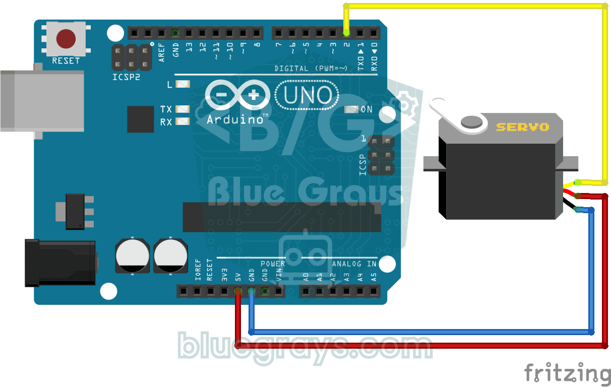
Using a Servo Motor
The arm of a small servo motor turns to three positions in turn: all the way to the start, right to the middle and all the way to the end, waiting two seconds at each stop. The Arduino tells the motor
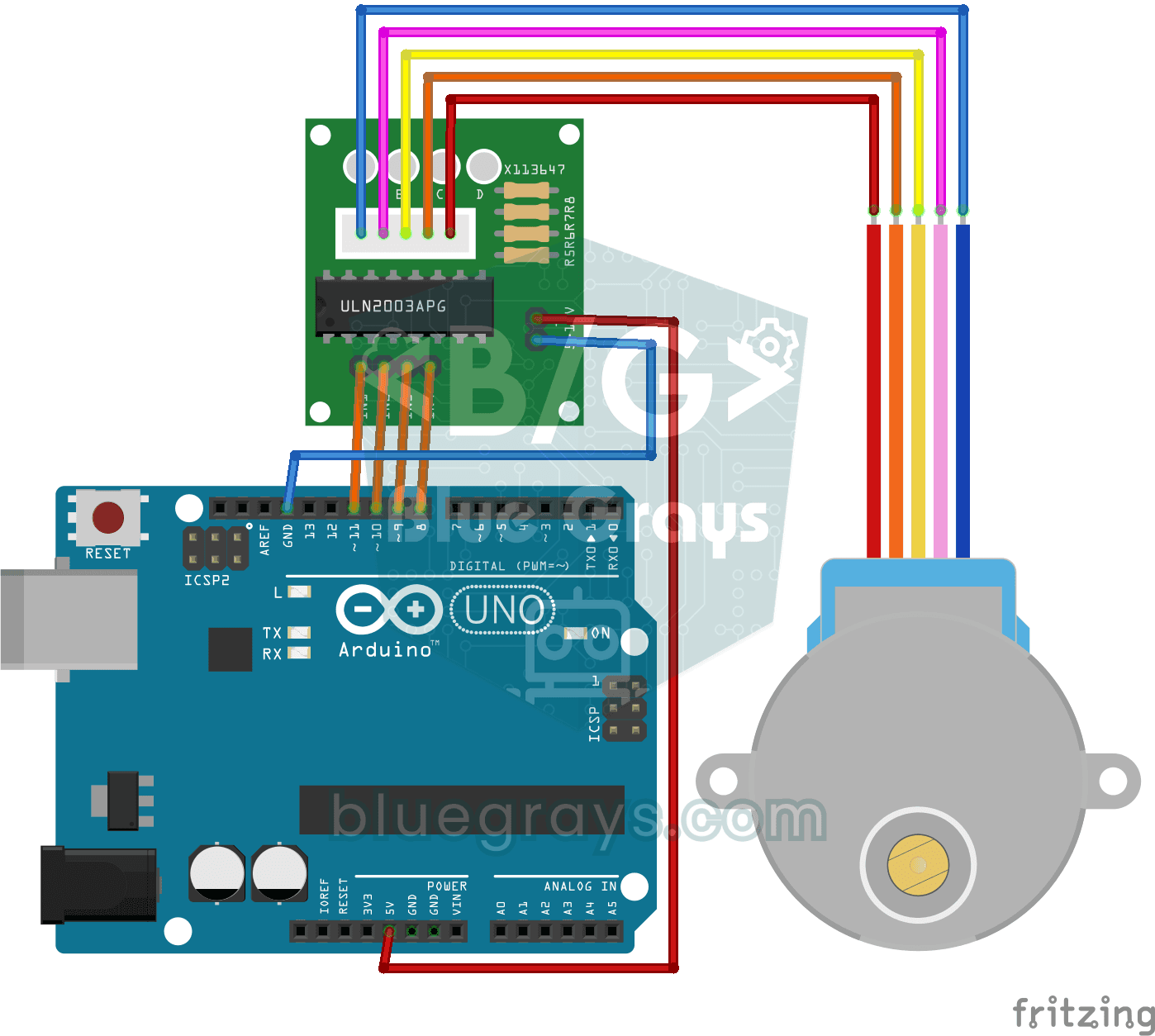
Using a Stepper Motor
A motor that turns step by step, exactly as far as you want, like the hand of a clock. Through a driver board, the Arduino turns a small stepper motor one full turn in one direction, waits a second, t

Bluetooth Controlled Car with L298N
Turn your phone into a remote and drive your own robot car. The Arduino receives commands from a remote-control app on your phone through a Bluetooth module and spins the wheels with a motor driver; t
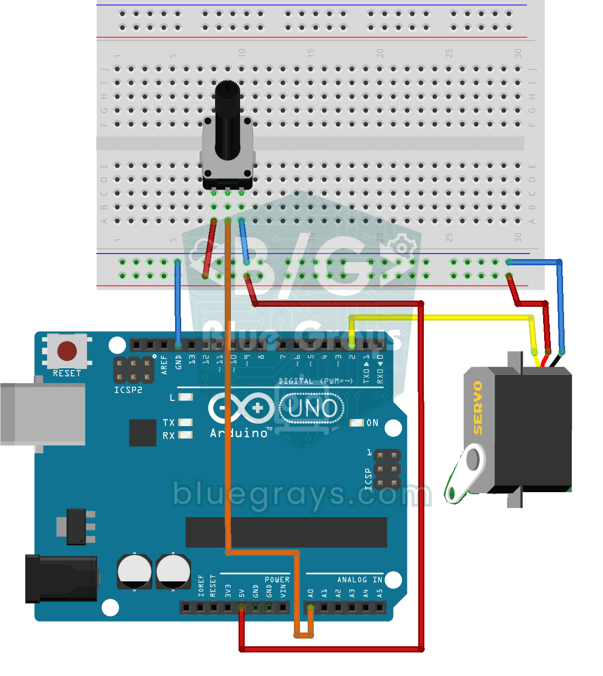
Servo Motor Operation with Potentiometer
As you turn the potentiometer knob, the servo motor's arm turns right along with it: one end of the knob means zero degrees, the other end means half a turn. The Arduino keeps reading the knob's posit
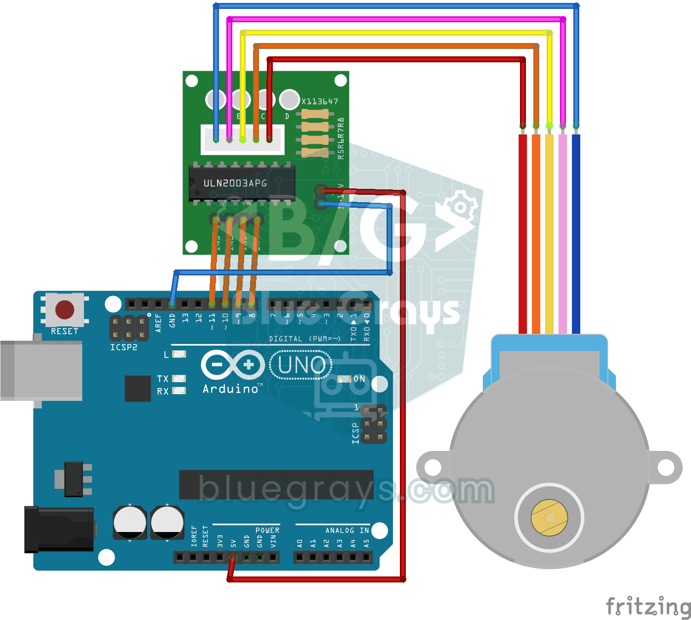
360-Degree Servo from a Stepper Motor
Teach an ordinary stepper motor to go to any angle you want, all the way around the circle. The Arduino works out how many steps each angle takes; the motor moves to 0, 90, 45, 180, 135 and 360 degree

Obstacle Avoidance Robot
How about building a smart vehicle that finds its own way? The Obstacle Avoidance Robot constantly scans its surroundings thanks to the ultrasonic sensor in front of it. When it encounters an obstacle

ESP32 Servo Motor (Potentiometer Control)
In this project, we control an SG90 servo motor using a potentiometer. We adjust the servo angle by mapping the analog value read from the potentiometer to the 0–180-degree range. The ESP32Servo library generates servo signals on suitable output-capable GPIO pins of the ESP32; this project uses GPIO 18. This is a fundamental control method for robotic arms, camera gimbals, and automatic door mechanisms.

ESP32 RFID Door Lock (RC522 + Servo + OLED + Buzzer + LED)
We’re building a smart door lock using an ESP32, an RC522 RFID module, an SG90 servo motor, an SSD1306 OLED display, an active buzzer, and 2 LEDs. When a card is scanned, its UID is compared to the list of authorized cards stored in the code—if authorized, the servo motor rotates to unlock the door (green LED + 2 short beeps), and the door automatically locks again after 5 seconds. For an unauthorized card, the red LED lights up, a warning is given with 3 rapid beeps, and the captured UID is dis