
VL53L0X Arduino Tutorial: Laser Distance Sensor, 2 m Range
How do you use the VL53L0X laser distance sensor with Arduino, ESP32 and Pico? I2C wiring, ranging profiles, multiple sensors with XSHUT and an HC-SR04 comparison.

The VL53L0X is a ToF (Time of Flight) laser distance sensor, one of the smallest and most precise ways to measure distance with Arduino. Made by STMicroelectronics, the chip sends out an invisible 940 nm laser pulse, measures how long the light takes to bounce off the target and return, and gives the result directly in millimetres. The stamp-sized module connects with just the two I2C data wires; it measures up to about 1.2 metres in the default mode and up to 2 metres in long-range mode.
In this guide you'll learn step by step how the VL53L0X works, how to connect it to an Arduino Uno, ESP32 and Raspberry Pi Pico, the difference between the four ranging profiles, and how to put several sensors on the same I2C bus using the XSHUT pin. You'll also compare it with the popular ultrasonic HC-SR04 distance sensor and see which one makes more sense for which project.
What is the VL53L0X and how does it work?
Inside the sensor there are two main parts: a VCSEL (vertical-cavity surface-emitting laser) that emits light, and an array of SPADs (single-photon avalanche diodes) that can detect even a single photon. The VCSEL sends very short light pulses, the SPAD array catches the returning photons and the chip measures the time in between. Distance comes from a simple formula: d = c × t / 2. Here c is the speed of light (about 300,000 km/s), and because the light travels the path twice, the result is divided by two. For an object 1 metre away, the round trip takes only 6.67 nanoseconds. Measuring such a short time with a single pulse is almost impossible, so the chip collects statistics from thousands of pulses and does the calculation internally; you simply read the finished result.
The laser is Class 1, so it isn't dangerous to the eye in normal use, and because it's infrared you can't see it. The sensor's field of view is about 25 degrees, so measurement happens inside a narrow cone. That lets you aim much better than with the wide sound wave of the HC-SR04; you can measure a small object at the edge of a table without picking up the wall beside it. Because the result depends on the speed of light, it's hardly affected by air temperature or humidity.
| Feature | Value |
|---|---|
| Chip | STMicroelectronics VL53L0X |
| Measuring principle | Time of flight (ToF), 940 nm VCSEL laser, Class 1 |
| Range | About 3 cm – 1.2 m (default), up to 2 m (long-range mode, dark environment, white target) |
| Resolution | 1 mm |
| Accuracy | About ±3% – ±5% depending on the mode |
| Field of view | About 25° |
| Measurement time | 20 ms – 200 ms (depending on the timing budget) |
| Supply | Chip 2.6–3.5 V; most modules have a regulator, 3.3–5 V |
| Current | About 19 mA while ranging, a few µA in standby |
| Interface | I2C, up to 400 kHz, default address 0x29 |
| Pins | VIN, GND, SCL, SDA, GPIO1 (interrupt), XSHUT (shutdown) |
VL53L0X or HC-SR04?
Both sensors measure distance, but their physics are completely different. The HC-SR04 sends a 40 kHz sound wave and listens for the echo; sound travels at about 343 m/s, so timing is easy and the range reaches 4 metres. However, the wide sound cone also picks up objects at the sides, and fabric, foam and angled surfaces absorb or deflect the sound. The VL53L0X measures with light: it's tiny, aims at the target with a narrow angle, is more stable at short distances, and thanks to I2C many sensors can share one bus. On the other hand, direct sunlight, very dark or mirror-like shiny surfaces and glass give it trouble. In short: if you need a small, fast measurement under 2 metres, choose the VL53L0X; if you need longer range and outdoor use, the HC-SR04 makes more sense. For other options, see the distance sensor comparison.
| Feature | VL53L0X | HC-SR04 |
|---|---|---|
| Measuring principle | Laser light time of flight (940 nm) | Ultrasonic sound echo (40 kHz) |
| Range | About 3 cm – 2 m | About 2 cm – 4 m |
| Measuring cone | About 25°, narrow and well defined | About 15° measuring angle, sound spreads wider |
| Resolution | 1 mm | About 3 mm (±1 cm in practice) |
| Connection | I2C (SDA, SCL) | 2 digital pins (Trig, Echo) |
| Multiple sensors | On the same I2C bus with XSHUT | A separate pin for each sensor, they can hear each other's echo |
| Supply | 3.3–5 V (module) | 5 V |
| Size | About 25 × 13 mm | About 45 × 20 mm |
| Struggles with | Black or mirror-like surfaces, glass, sunlight | Fabric, foam, angled surfaces, noisy environments |
VL53L0X wiring: Arduino Uno, ESP32 and Pico
Most modules on the market (such as the GY-530 and GY-VL53L0XV2) carry a 2.8 V regulator, pull-up resistors for the I2C lines and a pull-up resistor for XSHUT. That means you can connect the module to the Uno's 5V pin, or to the 3V3 pin on the ESP32 and Pico. Most cheap modules talk to the Uno without trouble; still, for projects that will run for a long time you can use a logic level converter to protect the I2C lines. If you're curious how the I2C bus works, read What is I2C. GPIO1 is an interrupt output that signals when a measurement is done; you don't need to connect it for basic use.
| VL53L0X pin | Arduino Uno | ESP32 | Raspberry Pi Pico |
|---|---|---|---|
| VIN | 5V (or 3.3V) | 3V3 | 3V3(OUT) |
| GND | GND | GND | GND |
| SCL | A5 | GPIO 22 | GP5 |
| SDA | A4 | GPIO 21 | GP4 |
| XSHUT (optional) | D4 (D5 for the 2nd sensor) | GPIO 25 | GP6 |
| GPIO1 (optional) | Not connected | Not connected | Not connected |
Step by step: your first measurement with Arduino
- Wire it up according to the table: VIN → 5V, GND → GND, SDA → A4, SCL → A5.
- If there's a yellow or orange protective tape on the sensor, peel it off carefully; the tape ruins the measurement completely.
- In the Arduino IDE open the Library Manager, type VL53L0X and install the library by Pololu. Adafruit_VL53L0X works too, but it includes ST's full API and takes much more memory on the Uno. If you get stuck installing it, see adding Arduino libraries.
- Upload the code below and open the Serial Monitor at 115200 baud.
- Move your hand towards and away from the sensor and watch the values change in millimetres and centimetres.
1#include <Wire.h>
2#include <VL53L0X.h>
3
4VL53L0X sensor;
5
6void setup() {
7  Serial.begin(115200);
8  Wire.begin();                          // Uno: SDA=A4, SCL=A5
9  sensor.setTimeout(500);                // 500 ms cevap bekle / wait 500 ms for a reply
10  if (!sensor.init()) {
11    Serial.println(F("VL53L0X bulunamadi / not found"));
12    while (1) {}
13  }
14  sensor.startContinuous();              // sürekli ölçüm / continuous ranging
15}
16
17void loop() {
18  uint16_t mm = sensor.readRangeContinuousMillimeters();
19  if (sensor.timeoutOccurred()) {
20    Serial.println(F("Zaman asimi / Timeout"));
21    return;
22  }
23  if (mm > 2000) {                       // geçerli yansıma yok / no valid return
24    Serial.println(F("Menzil disi / Out of range"));
25  } else {
26    Serial.print(mm);
27    Serial.print(F(" mm = "));
28    Serial.print(mm / 10.0, 1);
29    Serial.println(F(" cm"));
30  }
31  delay(100);
32}| Command | What it does |
|---|---|
| sensor.setTimeout(500) | Stops waiting if the sensor doesn't answer within 500 ms, so the code doesn't hang forever. |
| sensor.init() | Loads ST's setup sequence and runs SPAD calibration; if it returns false, the sensor wasn't found on the I2C bus. |
| sensor.startContinuous() | Makes the sensor measure back to back without pause. |
| sensor.readRangeContinuousMillimeters() | Returns the latest measurement in millimetres; with no target you get a value around 8190. |
| sensor.timeoutOccurred() | Returns true if the last read timed out (the value is then 65535). |
VL53L0X ranging modes
Three settings determine measurement quality on the VL53L0X: the timing budget (the time given to one measurement), the signal rate limit (the weakest return that counts as valid) and the VCSEL pulse period (the length of the laser pulses). The larger the budget, the more photons the sensor collects and the more stable the reading, but it gets slower; a 200 ms budget means only 5 measurements per second. Lowering the signal limit from the default 0.25 MCPS to 0.1 MCPS accepts weaker returns and extends range, but raises the risk of wrong readings. Raising the pulse periods from the default 14 and 10 to 18 and 14 sends more energy to distant targets. ST defines these settings as four ready-made profiles; in the code below you can pick the one you want by removing the comment marker at the start of its line. You can also combine the long-range setting with a speed or accuracy setting.
| Profile | Timing budget | Typical range | Accuracy | When to use |
|---|---|---|---|---|
| Default | About 30 ms | 1.2 m | About ±3–4% | General-purpose measurement |
| High accuracy | 200 ms | 1.2 m | Under ±3% | Level measurement, precise ruler |
| Long range | 33 ms | 2 m | About ±4% | Dark environment, distant target |
| High speed | 20 ms | 1.2 m | About ±5% | Fast robot, hand gesture detection |
1#include <Wire.h>
2#include <VL53L0X.h>
3
4VL53L0X sensor;
5
6// Profil seç: istediğin satırın yorumunu kaldır / Pick a profile: uncomment the line you want
7#define UZUN_MENZIL         // uzun menzil / long range
8//#define YUKSEK_HIZ        // yüksek hız / high speed
9//#define YUKSEK_DOGRULUK   // yüksek doğruluk / high accuracy
10
11void setup() {
12  Serial.begin(115200);
13  Wire.begin();
14  sensor.setTimeout(500);
15  if (!sensor.init()) {
16    Serial.println(F("Sensor yok / No sensor"));
17    while (1) {}
18  }
19
20#if defined UZUN_MENZIL
21  sensor.setSignalRateLimit(0.1);                                  // varsayılan 0.25 MCPS / default 0.25 MCPS
22  sensor.setVcselPulsePeriod(VL53L0X::VcselPeriodPreRange, 18);    // varsayılan 14 / default 14
23  sensor.setVcselPulsePeriod(VL53L0X::VcselPeriodFinalRange, 14);  // varsayılan 10 / default 10
24#endif
25
26#if defined YUKSEK_HIZ
27  sensor.setMeasurementTimingBudget(20000);    // 20 ms
28#elif defined YUKSEK_DOGRULUK
29  sensor.setMeasurementTimingBudget(200000);   // 200 ms
30#endif
31}
32
33void loop() {
34  Serial.print(sensor.readRangeSingleMillimeters());   // tek seferlik ölçüm / single-shot ranging
35  if (sensor.timeoutOccurred()) {
36    Serial.print(F(" ZAMAN ASIMI / TIMEOUT"));
37  }
38  Serial.println();
39}
Multiple VL53L0X sensors: changing the address with XSHUT
Every VL53L0X leaves the factory with the same 0x29 address, and this address can't be changed permanently. If you connect two sensors directly on the same bus, both answer at the same time and communication breaks. The solution is the XSHUT pin: while XSHUT is LOW the sensor is completely off and invisible on the I2C bus. At startup you wake the sensors one by one and give each a new address in software. The new address is only valid until power is cut or XSHUT goes LOW again, so this is done in setup() on every boot. With this method it's easy to fit a robot with three sensors, left, centre and right; in practice the limit is the number of free digital pins and the total cable length.
- Connect the VIN, GND, SDA and SCL pins of all sensors to the shared bus; connect each sensor's XSHUT pin to a separate digital pin (D4 and D5 in the example).
- At the start of setup(), set all XSHUT pins LOW to shut every sensor down.
- Wake sensor 1, start it with init() and give it its new address with setAddress(0x30).
- Wake sensor 2, start it and give it 0x31; if there are more sensors, continue with 0x32, 0x33 and so on.
- Start continuous ranging on all sensors and read each one through its own object.
1#include <Wire.h>
2#include <VL53L0X.h>
3
4const uint8_t XSHUT_1 = 4;
5const uint8_t XSHUT_2 = 5;
6
7VL53L0X sensor1;
8VL53L0X sensor2;
9
10void setup() {
11  Serial.begin(115200);
12  Wire.begin();
13
14  pinMode(XSHUT_1, OUTPUT);
15  pinMode(XSHUT_2, OUTPUT);
16  digitalWrite(XSHUT_1, LOW);    // iki sensörü de kapat / shut down both sensors
17  digitalWrite(XSHUT_2, LOW);
18  delay(10);
19
20  pinMode(XSHUT_1, INPUT);       // 1. sensörü aç, modülün pull-up direnci HIGH yapar / wake sensor 1, module pull-up pulls it HIGH
21  delay(10);
22  sensor1.setTimeout(500);
23  if (!sensor1.init()) {
24    Serial.println(F("Sensor 1 yok / Sensor 1 missing"));
25    while (1) {}
26  }
27  sensor1.setAddress(0x30);      // yeni adres / new address
28
29  pinMode(XSHUT_2, INPUT);       // 2. sensörü aç / wake sensor 2
30  delay(10);
31  sensor2.setTimeout(500);
32  if (!sensor2.init()) {
33    Serial.println(F("Sensor 2 yok / Sensor 2 missing"));
34    while (1) {}
35  }
36  sensor2.setAddress(0x31);
37
38  sensor1.startContinuous();
39  sensor2.startContinuous();
40}
41
42void loop() {
43  Serial.print(F("Sol / Left: "));
44  Serial.print(sensor1.readRangeContinuousMillimeters());
45  Serial.print(F(" mm   Sag / Right: "));
46  Serial.print(sensor2.readRangeContinuousMillimeters());
47  Serial.println(F(" mm"));
48  delay(100);
49}VL53L0X with the ESP32
On the ESP32 the same Pololu library works without changes. The default I2C pins are GPIO 21 (SDA) and GPIO 22 (SCL); stating them explicitly with Wire.begin(21, 22) saves you surprises on different boards. Because the ESP32's pins are 3.3 V, you can drive XSHUT HIGH directly; there's no need for the INPUT method used on the Uno. The example below measures with a 50 ms budget, averages the last 5 readings and turns on the board's built-in LED when an object comes closer than 15 cm. Averaging is the simplest way to smooth jumpy values; for more advanced methods, see sensor data filtering. If you want to watch the distance on your phone, you can combine the code with the ESP32 web server example.
1#include <Wire.h>
2#include <VL53L0X.h>
3
4const int SDA_PIN = 21;
5const int SCL_PIN = 22;
6const int LED_PIN = 2;            // çoğu DevKit'te dahili LED / onboard LED on most DevKits
7const uint16_t ESIK_MM = 150;     // uyarı eşiği / warning threshold
8const uint8_t N = 5;              // ortalama için örnek sayısı / samples for averaging
9
10VL53L0X sensor;
11uint16_t olcumler[N];
12uint8_t sira = 0;
13
14uint16_t olc() {
15  uint16_t mm = sensor.readRangeContinuousMillimeters();
16  if (mm > 2000) mm = 2000;       // menzil dışını sınırla / clamp out-of-range values
17  return mm;
18}
19
20void setup() {
21  Serial.begin(115200);
22  pinMode(LED_PIN, OUTPUT);
23  Wire.begin(SDA_PIN, SCL_PIN);
24  Wire.setClock(400000);          // hızlı I2C / fast-mode I2C
25  sensor.setTimeout(500);
26  if (!sensor.init()) {
27    Serial.println("VL53L0X bulunamadi / not found");
28    while (true) delay(1000);
29  }
30  sensor.setMeasurementTimingBudget(50000);   // 50 ms bütçe / 50 ms budget
31  sensor.startContinuous();
32  for (uint8_t i = 0; i < N; i++) olcumler[i] = olc();   // diziyi doldur / pre-fill the buffer
33}
34
35void loop() {
36  uint16_t mm = olc();
37  if (sensor.timeoutOccurred()) {
38    Serial.println("Zaman asimi / Timeout");
39    return;
40  }
41  olcumler[sira] = mm;
42  sira = (sira + 1) % N;
43
44  uint32_t toplam = 0;
45  for (uint8_t i = 0; i < N; i++) toplam += olcumler[i];
46  uint16_t ortalama = toplam / N;
47
48  digitalWrite(LED_PIN, ortalama < ESIK_MM ? HIGH : LOW);
49  Serial.printf("Ham / Raw: %u mm   Ortalama / Average: %u mm\n", (unsigned)mm, (unsigned)ortalama);
50  delay(50);
51}
Raspberry Pi Pico and VL53L0X with MicroPython
MicroPython has no built-in module for the VL53L0X; you need to copy the community-made vl53l0x.py driver file to the Pico with Thonny. These drivers port ST's initialisation sequence to Python and usually offer start(), read() and stop() functions; check the function names in your driver's file once. For wiring we use I2C0 on GP4 (SDA) and GP5 (SCL); a scan should show 0x29 (41 in decimal). The Pin("LED") expression used in the code selects the built-in LED on both the Pico and Pico W in MicroPython 1.20 and later. The same XSHUT logic applies when using several sensors on the Pico; since the Pico runs at 3.3 V, you can drive the XSHUT pins HIGH directly. If you're new to MicroPython, take a look at MicroPython basics first.
1from machine import Pin, I2C
2import time
3from vl53l0x import VL53L0X                  # vl53l0x.py Pico'da olmalı / must be on the Pico
4
5i2c = I2C(0, sda=Pin(4), scl=Pin(5), freq=400000)
6print("I2C:", [hex(a) for a in i2c.scan()])  # 0x29 görmelisin / you should see 0x29
7
8tof = VL53L0X(i2c)                           # varsayılan adres 0x29 / default address 0x29
9led = Pin("LED", Pin.OUT)                    # dahili LED (Pico ve Pico W) / onboard LED (Pico and Pico W)
10ESIK_MM = 150                                # uyarı eşiği / warning threshold
11
12tof.start()                                  # sürekli ölçüm / continuous ranging
13try:
14    while True:
15        mm = tof.read()
16        if mm > 2000:
17            print("Menzil disi / Out of range")
18        else:
19            print(mm, "mm")
20        led.value(1 if mm < ESIK_MM else 0)
21        time.sleep_ms(100)
22finally:
23    tof.stop()                               # ölçümü durdur / stop ranging
Tips for accurate measurements
- Target colour matters: White and matte surfaces reflect light well; on black, dark grey or velvet-like surfaces the range can drop to half or less.
- Avoid sunlight: Sunlight has a strong infrared component and raises the sensor's background noise. Outdoors, keep the sensor in the shade or choose the HC-SR04.
- Watch out for cover glass: If you put the sensor inside a box, glass or acrylic in front of it reflects part of the light back (crosstalk) and makes the reading too short. If you need a cover, choose a thin, IR-transparent material as close to the sensor as possible.
- Mirror-like shiny surfaces: Light can bounce off an angled shiny surface in another direction; keep the sensor as perpendicular to the surface as you can.
- Small targets: The 25-degree cone widens with distance; at 1 metre it sees an area about 44 cm across. When measuring a small object from far away, the wall behind it can also affect the result.
- Keep wires short: The I2C bus degrades on long wires; for connections over 30 cm, drop the speed to 100 kHz and route the wires away from motor cables.
VL53L0X project ideas
- Garage parking assistant: Measure the car's distance to the wall and change the LED colour as it gets closer. For a detailed example, see the Arduino parking system post.
- Touchless bin or soap dispenser: Have a servo open the lid when your hand comes within 10 cm; in the smart trash can project you can use the VL53L0X instead of an HC-SR04.
- Three-eyed obstacle-avoiding robot: Mount one sensor on the left, centre and right and put them on one bus with XSHUT; an obstacle-avoiding robot makes much smarter turns.
- Pet food or grain level gauge: Mount it in the hopper lid and show the remaining amount as a percentage; it pairs well with the automatic pet feeder project.
- Hand-gesture dimmer: Turn the distance of your hand to the sensor into LED brightness with PWM; for example 5 cm is full brightness and 30 cm is off.
- Digital ruler: Print the measured distance in big digits on an OLED display and turn it into a desktop measuring tool.
Common mistakes and how to fix them
| Symptom | Likely cause | Fix |
|---|---|---|
| init() returns false, sensor not found | SDA and SCL swapped, no power, or wrong pin | Look for address 0x29 with an I2C scanner; check that on the Uno SDA = A4 and SCL = A5 |
| Values stuck around 8190 | Target out of range, protective tape not removed, or the surface is too dark | Remove the tape, bring the target closer, try the long-range profile |
| Measurement off by a few centimetres | Module offset or a cover glass in front | Measure at a known distance and subtract the difference in code; remove or change the cover |
| Values keep jumping | Short timing budget, ambient light, small target | Raise the budget to 50–200 ms, average several readings |
| 65535 and a timeout message | Long or loose I2C wire, sensor was reset | Shorten the wires, tighten the connections, restart the sensor |
| One of two sensors doesn't respond at all | Address clash or missing XSHUT connection | Check the XSHUT pins, wake the sensors in turn and give them different addresses |
| Readings too short outdoors | Infrared noise from sunlight | Keep the sensor in the shade, use the high-accuracy profile, or switch to the HC-SR04 |
With its small size, narrow field of view and millimetre resolution, the VL53L0X adds a precise eye to projects from robots to touchless switches; once you pick the right profile and correct the offset, you get far more stable results at the short distances where ultrasonic sensors struggle. In the BlueGrays app you can explore distance measuring, parking sensor, height meter and obstacle-avoiding robot projects with step-by-step circuit diagrams and code, and easily adapt the same logic to your own project with the VL53L0X.
Frequently asked questions
How far can the VL53L0X measure?
With default settings the reliable range is about 1.2 metres. In the long-range profile, in a dark environment and with a white, well-reflecting target, it can measure up to 2 metres. On grey or dark surfaces and in sunlight this range drops noticeably.
Is the VL53L0X or the HC-SR04 better?
It depends on where you use it. The VL53L0X is small, narrow-angle and more stable under 2 metres, and thanks to I2C several sensors connect easily on one bus. The HC-SR04 measures up to 4 metres, isn't affected by sunlight and detects glass, but struggles with soft surfaces like fabric.
What is the VL53L0X I2C address and how do you change it?
The default 7-bit address is 0x29; in 8-bit notation it's also written as 0x52. You change the address in software with setAddress(), but it isn't permanent; it returns to 0x29 when power is cut or XSHUT goes LOW. With multiple sensors you need to wake them in turn with XSHUT and assign addresses on every boot.
Why does the VL53L0X show 8190?
The Pololu library returns a value like 8190 or 8191 when the sensor finds no valid return in its field of view. The target may be out of range, the surface may be too dark, or the protective tape on the sensor may not have been removed. A value of 65535 means an I2C timeout; check the wiring and power.
Does the VL53L0X work in sunlight?
It works, but performance drops. Sunlight contains a strong infrared component, which raises the sensor's background noise and can cut the range to half or less. Keeping the sensor in the shade outdoors, choosing the high-accuracy profile and using it at short distances all help.
What is the difference between the VL53L0X and the VL53L1X?
The VL53L1X is a newer member of the same family; it measures up to 4 metres and lets you choose only part of the field of view (ROI). The VL53L0X is limited to 2 metres but is cheaper and more than enough for short-range projects. The two sensors use different libraries, so code can't be transferred one to one.
Projects to build after reading this
See all projects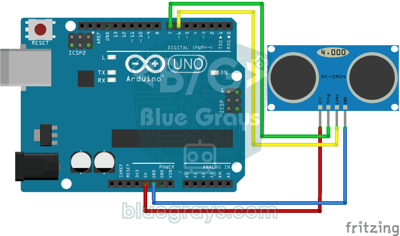
HC-SR04 Distance Measurement (Serial Display)
The HC-SR04 sensor works just like a bat finding its way in the dark: it sends out a sound you cannot hear, listens for the echo and measures how far away the object in front of it is.
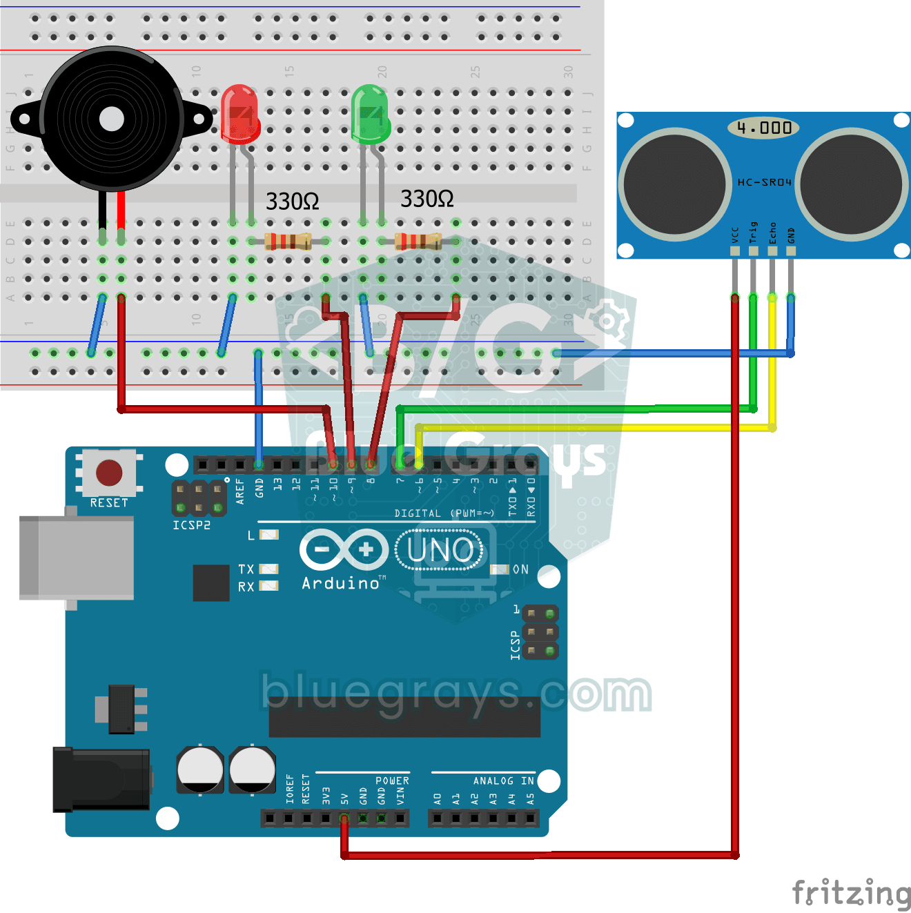
Parking Sensor with HC-SR04
A mini version of a car's parking sensor: the closer something gets, the faster the beeps.
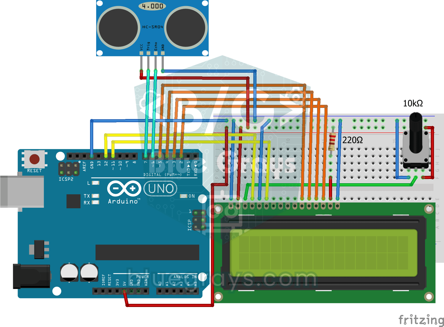
Measuring Distance Using LCD Display
A tool that measures distance without a ruler: move your hand back and forth in front of the sensor and watch the number change.
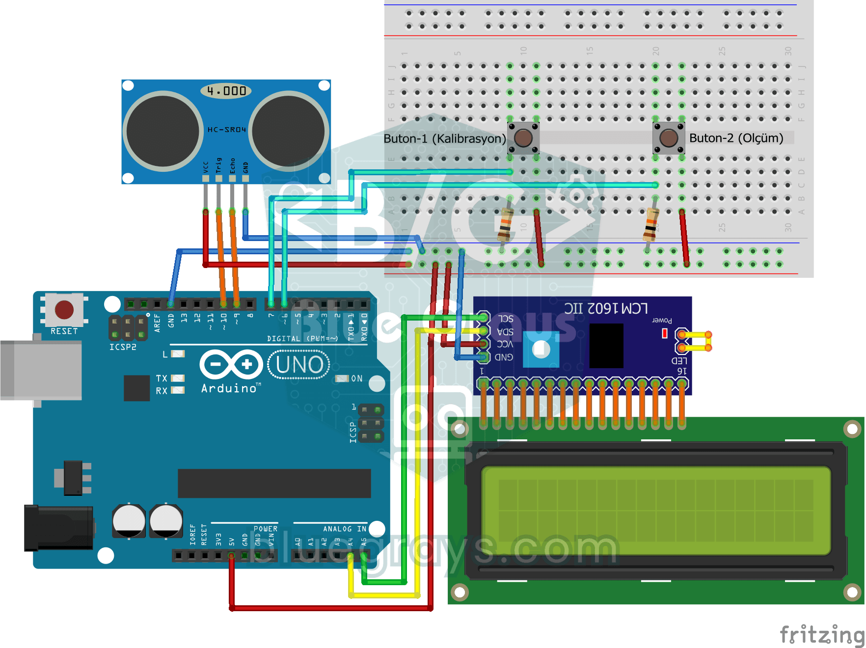
Height Measurement Project
A height meter that hangs from a door frame and tells you, in centimetres, how tall the person standing under it is.

Reading Reflection (Proximity) with TCRT5000
With a small sensor that sends out invisible light and measures how much bounces back, you can detect the surface in front of it.

Obstacle Avoidance Robot
How about building a smart vehicle that finds its own way? The Obstacle Avoidance Robot constantly scans its surroundings thanks to the ultrasonic sensor in front of it.

ESP32 HC-SR04 Ultrasonic Distance Sensor
The HC-SR04 ultrasonic sensor measures distance by timing how long its sound pulse takes to bounce off an object and return (time of flight). In this project the ESP32 sends a 10-microsecond pulse to the TRIG pin and reads the echo time from the ECHO pin with pulseIn(). The distance is shown in cm on a 16x2 I2C LCD. The HC-SR04 runs on 5V, so the ECHO pin needs a voltage divider, or the ESP32's 3.3V GPIO gets damaged.

ESP32 Parking Sensor (HC-SR04 + 5-LED Bar + Buzzer + OLED)
The ESP32 version of a car parking sensor! The HC-SR04 ultrasonic sensor measures the distance to the object in front. As it gets closer, a 5-LED bar fills up (green → yellow → red) and the buzzer beeps faster. Very close (under 10 cm), a continuous alarm sounds and all LEDs light up. The SSD1306 OLED display shows the live distance in cm in large text, plus a status message.