
433MHz RF Module Arduino Guide: Transmitter, Receiver, Antenna
433MHz RF module Arduino guide: wire the FS1000A transmitter and XY-MK-5V receiver, add a 17.3 cm antenna, send RadioHead messages, clone remotes with RCSwitch.
A 433MHz RF module is the cheapest way to add a wireless link to an Arduino project: a set made of a transmitter (FS1000A) and a receiver (XY-MK-5V) costs very little, connects with a single data wire and, with a 17 cm wire antenna, carries a signal tens of metres. Remote-controlled sockets, wireless doorbells, shutter remotes, door and window sensors and the outdoor sensors of weather stations mostly use the same frequency too. That means these modules let you send data between two Arduinos and also read the codes of the ready-made remotes in your home and send them again from an Arduino.
In this guide you'll learn how the modules work with ASK (OOK) modulation, why the antenna should be 17.3 cm long and how to wire them to an Arduino Uno, an ESP32 and a Raspberry Pi Pico. Then you'll send text and sensor data between two Arduinos with the RadioHead library, read and clone a socket's remote code with the RCSwitch library, see how to increase the range and compare the module with the nRF24L01.
What is a 433MHz RF module and how does it work?
The set consists of two separate boards. The small, square FS1000A transmitter (also sold as XY-FST) switches a 433.92 MHz carrier wave on and off according to the signal on its DATA pin. The longer XY-MK-5V receiver picks up that signal from the air and outputs it again as 0s and 1s on its DATA pin. In other words, the modules themselves have no protocol, address or error checking; their only job is to carry a digital signal wirelessly to the other side. Packing, verifying and decoding the data is the job of the library on the Arduino. Communication is one-way: the transmitter only sends, and the receiver only listens.
| Feature | FS1000A (transmitter) | XY-MK-5V (receiver) |
|---|---|---|
| Frequency | 433.92 MHz (a 315 MHz version also exists) | 433.92 MHz |
| Supply voltage | 3–12 V | 5 V |
| Current | About 9–40 mA while transmitting (depends on voltage) | About 4 mA |
| Modulation | ASK / OOK | ASK / OOK, super-regenerative receiver |
| Data rate | Up to ~10 kbps (1–4 kbps in practice) | Same limit as the transmitter |
| Output power / sensitivity | About 10 mW, rises with voltage | About −105 dBm |
| Pins | DATA, VCC, GND + ANT solder pad | VCC, DATA, DATA, GND + ANT solder pad |
| Size | About 19 × 19 mm | About 30 × 14 mm |
The receiver's two DATA pins are connected together on the board, so it doesn't matter which one you use. The XY-MK-5V is a cheap but not very selective super-regenerative receiver: its frequency is set by an adjustable coil on the board and it's easily affected by nearby interference. Don't turn the screw in that coil; if the factory setting is lost, the receiver stops hearing the transmitter. For more stable results, superheterodyne receivers such as the RXB6 are more sensitive and also run on 3.3 V. The set is also sold in a 315 MHz version; the transmitter and receiver must be on the same frequency, and the metal resonator on the transmitter board usually has the frequency printed on it.
ASK (OOK) modulation: why do you need a library?
In OOK (On-Off Keying), the simplest form of ASK (Amplitude Shift Keying), the carrier is switched on for a 1 bit and off for a 0 bit. It sounds easy, but the receiver has a quirk: its automatic gain control (AGC) turns the gain all the way up when there's no signal, mistakes the noise in the air for data and outputs random pulses on the DATA pin all the time. That's why connecting the transmitter straight to the Arduino's TX pin and the receiver to the RX pin and trying to communicate with Serial.print usually ends in garbage characters.
The RH_ASK driver in the RadioHead library solves this problem as follows: before each packet it sends a 36-bit preamble and a 12-bit start symbol so the receiver's gain can settle. It then turns every byte into two DC-balanced 6-bit symbols (4-to-6 encoding) and adds a 16-bit CRC to the end of the packet. The receiver silently drops packets whose CRC doesn't match, so only intact data gets through. RCSwitch, on the other hand, decodes the pulse-width coding used by remote control chips: each bit is represented by pulses that stay HIGH and LOW for set lengths of time.
433MHz antenna length: why 17.3 cm?
The modules have no antenna fitted; there's only a solder pad marked ANT. Without an antenna, a set only works over 1–3 metres. The most efficient simple antenna is a straight wire a quarter of a wavelength long: λ = c / f = 300,000,000 / 433,920,000 ≈ 0.69 m, and a quarter of that is about 17.3 cm. For 315 MHz modules the same calculation gives 23.8 cm. Solder one end of a single-core wire to the ANT pad and keep the wire straight and vertical; solder a wire of the same length to the receiver too and point both antennas in the same direction.
| Antenna | Length | Approximate range (open air) | Note |
|---|---|---|---|
| No antenna | — | 1–3 m | Only for testing on the desk |
| Straight wire (λ/4), transmitter at 5 V | 17.3 cm | 20–50 m | The easiest and most efficient option |
| Straight wire (λ/4), transmitter at 9–12 V | 17.3 cm | 50–100 m and more | Line of sight and height make a big difference |
| Ready-made helical (spring) antenna | 2–4 cm long | Shorter than with a straight wire | Fits inside an enclosure |
433MHz RF module wiring: Arduino Uno, ESP32 and Pico
| Module pin | Arduino Uno (RadioHead) | Arduino Uno (RCSwitch) | ESP32 | Raspberry Pi Pico |
|---|---|---|---|---|
| FS1000A VCC | 5V or external 9–12 V | 5V | VIN (5 V) | VBUS (5 V) |
| FS1000A DATA | D12 | D10 | GPIO 26 | GP15 |
| FS1000A GND | GND | GND | GND | GND |
| XY-MK-5V VCC | 5V | 5V | VIN (5 V) | VBUS (5 V) |
| XY-MK-5V DATA | D11 | D2 (interrupt pin) | GPIO 27 (through a voltage divider) | GP14 (through a voltage divider) |
| XY-MK-5V GND | GND | GND | GND | GND |
The transmitter works fine with a 3.3 V signal on its DATA pin, so on the ESP32 and Pico you can power it from 5 V and connect DATA straight to a GPIO. The transmitter voltage has the biggest effect on range: at 3.3 V the range drops noticeably, while at 9–12 V it increases several times over. Placing a 100 nF ceramic and a 10 µF electrolytic capacitor right next to the receiver's VCC and GND pins reduces supply noise and visibly improves reception.
Sending messages between two Arduinos with RadioHead
- Open the Library Manager in the Arduino IDE, search for RadioHead and install Mike McCauley's library. For details, see How to add a library to Arduino.
- Connect the transmitter to the first Arduino: DATA → D12, VCC → 5V, GND → GND.
- Connect the receiver to the second Arduino: DATA → D11, VCC → 5V, GND → GND.
- Solder a 17.3 cm wire to the ANT pad of each module.
- Upload the transmitter code to the first board and the receiver code to the second, then open the Serial Monitor on the receiver side at 9600 baud.
1#include <RH_ASK.h>
2#include <SPI.h>                  // RadioHead derlemesi için / needed for RadioHead to compile
3
4RH_ASK rf(2000, 11, 12);          // hız (bps), RX pini, TX pini / speed (bps), RX pin, TX pin
5unsigned int sayac = 0;
6
7void setup() {
8  Serial.begin(9600);
9  if (!rf.init()) Serial.println("RF init hatasi / failed");
10}
11
12void loop() {
13  char mesaj[24];
14  snprintf(mesaj, sizeof(mesaj), "Merhaba %u", sayac++);
15  rf.send((uint8_t *)mesaj, strlen(mesaj));
16  rf.waitPacketSent();            // paket bitene kadar bekle / wait until the packet is sent
17  Serial.print("Gonderildi / sent: ");
18  Serial.println(mesaj);
19  delay(1000);
20}1#include <RH_ASK.h>
2#include <SPI.h> // RadioHead derlemesi için / needed for RadioHead to compile
3
4RH_ASK rf(2000, 11, 12); // vericiyle aynı hız / same speed as the transmitter
5
6void setup() {
7 Serial.begin(9600);
8 if (!rf.init()) Serial.println("RF init hatasi / failed");
9}
10
11void loop() {
12 uint8_t buf[RH_ASK_MAX_MESSAGE_LEN + 1]; // +1: metin sonu için / +1 for the string terminator
13 uint8_t len = RH_ASK_MAX_MESSAGE_LEN; // her turda yeniden ayarla / reset on every pass
14 if (rf.recv(buf, &len)) { // yalnız CRC doğruysa true / true only if the CRC is valid
15 buf[len] = '\0';
16 Serial.print("Alindi / received: ");
17 Serial.println((char *)buf);
18 }
19}| Command | What it does |
|---|---|
| RH_ASK rf(2000, 11, 12) | Speed 2000 bps, receiver on D11, transmitter on D12; the speed must match on both sides |
| rf.init() | Sets up the timer and pins; returns false if something is wrong |
| rf.send(data, length) | Starts sending a packet of up to 60 bytes |
| rf.waitPacketSent() | Waits until the packet has been fully transmitted |
| rf.recv(buf, &len) | If there's a new packet with a valid CRC, copies it into buf, updates len and returns true |
| RH_ASK_MAX_MESSAGE_LEN | The largest amount of data a single packet can carry: 60 bytes |
In the receiver code it's important to reset the len variable on every pass: recv() writes the size of the incoming packet into it, and on the next call that value is taken as the buffer size; if you don't reset it, longer messages get truncated. If everything is fine, you'll see the lines "Merhaba 0", "Merhaba 1" once a second in the Serial Monitor. If numbers are skipped, some packets were lost on the way; in that case check the antenna and the power supply.
Sending sensor data: a packet with a struct
In real projects, sending numbers is more efficient than sending text. You can gather your readings in a struct and send its bytes as they are. The transmitter below sends the value of an LDR or potentiometer on A0 and the state of the button on D2 five times a second. The receiver lights the LED on D13 when the remote button is pressed and notices lost packets.
1#include <RH_ASK.h>
2#include <SPI.h>
3
4struct __attribute__((packed)) Paket {   // iki tarafta birebir aynı olmalı / must be identical on both sides
5  uint16_t no;                           // paket numarası / packet number
6  int16_t deger;                         // analog değer / analog value
7  uint8_t buton;                         // 1 = basılı / 1 = pressed
8};
9
10RH_ASK rf;                               // varsayılan: 2000 bps, RX 11, TX 12 / defaults
11Paket p = {0, 0, 0};
12
13void setup() {
14  pinMode(2, INPUT_PULLUP);              // buton D2-GND / button D2-GND
15  rf.init();
16}
17
18void loop() {
19  p.no++;
20  p.deger = analogRead(A0);              // örneğin LDR ya da potansiyometre / e.g. LDR or potentiometer
21  p.buton = (digitalRead(2) == LOW);
22  rf.send((uint8_t *)&p, sizeof(p));
23  rf.waitPacketSent();
24  delay(200);
25}1#include <RH_ASK.h>
2#include <SPI.h>
3
4struct __attribute__((packed)) Paket {
5 uint16_t no;
6 int16_t deger;
7 uint8_t buton;
8};
9
10RH_ASK rf;
11const int LED = 13;
12uint16_t sonNo = 0;
13
14void setup() {
15 Serial.begin(9600);
16 pinMode(LED, OUTPUT);
17 rf.init();
18}
19
20void loop() {
21 Paket p;
22 uint8_t len = sizeof(p);
23 if (rf.recv((uint8_t *)&p, &len) && len == sizeof(p)) {
24 digitalWrite(LED, p.buton ? HIGH : LOW); // uzaktaki buton LED'i yakar / remote button lights the LED
25 if (sonNo != 0 && p.no != (uint16_t)(sonNo + 1)) {
26 Serial.println("Paket kaybi / packet lost");
27 }
28 sonNo = p.no;
29 Serial.print(p.no);
30 Serial.print(" A0 = ");
31 Serial.println(p.deger);
32 }
33}The __attribute__((packed)) keyword stops the compiler from adding padding between the fields. This matters: the same struct can take up 5 bytes on an Arduino Uno and 6 bytes on an ESP32, and the data gets shifted when two different boards talk to each other. Thanks to the packet number, the receiver can count the packets lost in between. Since 433MHz modules have no acknowledgement, it's a good habit to repeat important commands a few times. If you fit both a transmitter and a receiver on each side, you can also set up acknowledged communication with retries using RadioHead's RHReliableDatagram class.
Reading the codes of ready-made remotes with RCSwitch
Many remote-controlled sockets, wireless doorbells, shutter and garden gate remotes, as well as door, window and PIR alarm sensors, use code chips such as the EV1527 or PT2262. Each time a button is pressed, these chips send the same 12–24-bit code over and over with sync gaps in between. The RCSwitch library (called rc-switch in the Library Manager) decodes these codes. On the Uno, connect the receiver's DATA pin to an interrupt pin, that is D2 or D3, and upload the code below:
1#include <RCSwitch.h>
2
3RCSwitch rf = RCSwitch();
4
5void setup() {
6  Serial.begin(9600);
7  rf.enableReceive(digitalPinToInterrupt(2));   // alıcı DATA -> D2 (kesme pini) / receiver DATA -> D2 (interrupt pin)
8  Serial.println(F("Kumandanin tusuna bas / press a remote button"));
9}
10
11void loop() {
12  if (rf.available()) {
13    Serial.print(F("Kod / code: "));
14    Serial.print(rf.getReceivedValue());
15    Serial.print(F("  Bit: "));
16    Serial.print(rf.getReceivedBitlength());
17    Serial.print(F("  Protokol / protocol: "));
18    Serial.print(rf.getReceivedProtocol());
19    Serial.print(F("  Darbe / pulse: "));
20    Serial.print(rf.getReceivedDelay());
21    Serial.println(F(" us"));
22    rf.resetAvailable();                         // bir sonraki koda hazırlan / get ready for the next code
23  }
24}
Open the Serial Monitor and press a button on the remote; you'll see a line like "Kod / code: 5393 Bit: 24 Protokol / protocol: 1 Darbe / pulse: 350 us". Note down each button's code, bit length, protocol and pulse length; you'll need all four when cloning. On remotes with an EV1527, the first 20 of the 24 bits are the remote's ID and the last 4 are the button pressed, which is why the button codes of the same remote are very close to each other. In protocol 1 one unit lasts about 350 µs: a 0 bit is 1 unit HIGH and 3 units LOW, a 1 bit is 3 units HIGH and 1 unit LOW, and the sync is 1 unit HIGH and 31 units LOW.
| Remote chip | Code structure | Can RCSwitch clone it? |
|---|---|---|
| EV1527 (learning code) | 20-bit ID + 4-bit button, 24 bits in total | Yes |
| PT2262 / SC2262 | 12 tri-state (0, 1, F) bits; the address is set with DIP switches | Yes |
| HT6P20B | Fixed code, RCSwitch protocol 6 | Yes |
| Rolling code chips such as the HCS301 (KeeLoq) | Encrypted code that changes with every press | No |
Sending the remote code from an Arduino
To send the code you read, connect the transmitter's DATA pin to D10 and two buttons between D4 and D5 and GND. Every time you press a button, the Arduino repeats the code 10 times, just like the remote does; the socket's on and off buttons now live on your Arduino:
1#include <RCSwitch.h>
2
3RCSwitch rf = RCSwitch();
4const int BTN_AC = 4;            // "aç" butonu D4-GND / "on" button D4-GND
5const int BTN_KAPAT = 5;         // "kapat" butonu D5-GND / "off" button D5-GND
6
7void setup() {
8  pinMode(BTN_AC, INPUT_PULLUP);
9  pinMode(BTN_KAPAT, INPUT_PULLUP);
10  rf.enableTransmit(10);         // verici DATA -> D10 / transmitter DATA -> D10
11  rf.setProtocol(1);             // önce protokol... / protocol first...
12  rf.setPulseLength(350);        // ...sonra okuduğun darbe süresi / ...then the pulse length you read
13  rf.setRepeatTransmit(10);      // her gönderim 10 kez tekrarlanır / each send is repeated 10 times
14}
15
16void loop() {
17  if (digitalRead(BTN_AC) == LOW) {
18    rf.send(5393, 24);           // okuduğun "aç" kodu ve bit sayısı / the "on" code and bit length you read
19    delay(300);
20  }
21  if (digitalRead(BTN_KAPAT) == LOW) {
22    rf.send(5396, 24);           // okuduğun "kapat" kodu / the "off" code you read
23    delay(300);
24  }
25}
Because setProtocol() resets the pulse length to that protocol's default, always call setPulseLength() after it. If the socket doesn't respond, first enter the exact pulse length you read (e.g. 320 or 420 µs), then raise the repeat count to 15. Learning-code sockets offer one more shortcut: if you put the socket into learning mode and send any 24-bit code from the Arduino, the socket stores that code in its memory. So you can create your own codes without cloning any remote at all.
433MHz receiver with the ESP32: controlling a relay with a remote
The ESP32 is a great bridge for connecting 433MHz remotes to the Wi-Fi world. RCSwitch works on the ESP32 too, and since every ESP32 GPIO can take interrupts, you can connect the receiver to any safe pin you like. The code below reads the codes from a receiver connected to GPIO 27 (through a voltage divider); when your own remote's code arrives, it toggles the LED on GPIO 2 or a relay module. Because a remote sends its code many times for a single press, the program won't toggle again until the code has stopped for 600 ms:
1#include <RCSwitch.h>
2
3RCSwitch rf = RCSwitch();
4const int RX_PIN = 27;              // alıcı DATA, gerilim bölücüyle / receiver DATA, through a divider
5const int ROLE_PIN = 2;             // dahili LED ya da röle girişi / onboard LED or relay input
6const unsigned long KOD = 5393;     // kendi kumandanın kodu / your own remote's code
7bool durum = false;
8unsigned long sonGorulme = 0;
9
10void setup() {
11  Serial.begin(115200);
12  pinMode(ROLE_PIN, OUTPUT);
13  rf.enableReceive(digitalPinToInterrupt(RX_PIN));   // ESP32'de her GPIO kesme alır / every GPIO takes interrupts on the ESP32
14}
15
16void loop() {
17  if (rf.available()) {
18    unsigned long kod = rf.getReceivedValue();
19    Serial.printf("Kod / code: %lu  %u bit  protokol %u\n", kod, rf.getReceivedBitlength(), rf.getReceivedProtocol());
20    if (kod == KOD) {
21      // kumanda kodu art arda tekrarlar; yalnız yeni basışta değiştir / the remote repeats the code; toggle only on a new press
22      if (millis() - sonGorulme > 600) {
23        durum = !durum;
24        digitalWrite(ROLE_PIN, durum ? HIGH : LOW);
25      }
26      sonGorulme = millis();
27    }
28    rf.resetAvailable();
29  }
30}
You can build a lot on this foundation: forward incoming codes to Home Assistant over MQTT to add cheap 433MHz door sensors to your smart home, or control sockets from your phone with a transmitter on GPIO 26. RadioHead supports the ESP32 as well; the only difference is that you write the pins explicitly in the constructor: RH_ASK rf(2000, 27, 26, 25); (receiver 27, transmitter 26 and 25 as a free pin for PTT). If you're new to the ESP32, have a look at What is the ESP32?.
433MHz transmitter with the Raspberry Pi Pico and MicroPython
MicroPython has no ready-made equivalent of RCSwitch, but protocol 1's timing is so simple that you can write it yourself in a few lines. Connect the FS1000A's VCC to the Pico's VBUS (5 V) pin, DATA to GP15 and a button between GP16 and GND. When you press the button, the Pico sends the 24 bits starting from the most significant bit, just like RCSwitch, adds the sync pulse at the end and repeats the whole packet 10 times. If you don't know how to install MicroPython on the Pico yet, start with What is the Raspberry Pi Pico?.
1from machine import Pin
2import time
3
4tx = Pin(15, Pin.OUT, value=0)        # FS1000A DATA -> GP15
5buton = Pin(16, Pin.IN, Pin.PULL_UP)  # buton GP16-GND / button GP16-GND
6T = 350                               # darbe süresi µs (RCSwitch protokol 1) / pulse length µs (RCSwitch protocol 1)
7
8def darbe(yuksek, dusuk):             # süreler T cinsinden / durations in units of T
9    tx.value(1)
10    time.sleep_us(yuksek * T)
11    tx.value(0)
12    time.sleep_us(dusuk * T)
13
14def gonder(kod, bit=24, tekrar=10):
15    for _ in range(tekrar):
16        for i in range(bit - 1, -1, -1):   # en anlamlı bitten başla / start from the most significant bit
17            if (kod >> i) & 1:
18                darbe(3, 1)                # "1" biti: 3T HIGH, 1T LOW / bit "1"
19            else:
20                darbe(1, 3)                # "0" biti: 1T HIGH, 3T LOW / bit "0"
21        darbe(1, 31)                       # senkron: 1T HIGH, 31T LOW / sync
22
23while True:
24    if buton.value() == 0:                 # butona basıldı / button pressed
25        gonder(5393)                       # okuduğun kodu yaz / put the code you read here
26        time.sleep_ms(300)
For the Pico's 125 MHz processor, 350 µs pulses are a comfortable speed; Python's small delays stay well below the 60% timing tolerance of RCSwitch receivers. You can test the code straight away by placing an Arduino running the RCSwitch reader code next to it: the number you sent should appear in the Serial Monitor. On the receiving side you'd have to measure and decode the pulse lengths with timestamps; for that job an Arduino or ESP32 running RCSwitch is more practical.
Range and interference: carrying the signal further
- Don't forget the antenna: solder a straight 17.3 cm wire to both sides; this has the biggest effect on range.
- Raise the transmitter voltage: powering the FS1000A from 9–12 V noticeably increases its output power and range. Don't forget the common ground.
- Lower the speed: using 1000 bps instead of 2000 in RadioHead makes every bit last longer and lets the receiver decode weaker signals. Set the same speed on both sides.
- Line of sight and height: reinforced concrete walls, metal boxes and mounting close to the ground can halve the range; move the antennas outside metal enclosures and as high as possible.
- Clean up the power supply: motors, relays and switching adapters deafen the receiver. Give the receiver a filtered supply and keep the wires short.
- Use a better receiver: a superheterodyne receiver such as the RXB6 instead of the XY-MK-5V often reaches noticeably further with the same transmitter.
- Send it again: since there's no acknowledgement, send important commands 3–5 times and filter out the duplicates on the receiver with the packet number.
Remember that 433 MHz is a shared band: your neighbour's weather station, car keys and doorbells all transmit on the same frequency. In Europe and Turkey, the 433.05–434.79 MHz range is open for licence-free use by short-range devices, but the transmit power is limited to 10 mW (ERP) and you mustn't keep the channel busy all the time; rules vary by country, and in the US remotes more often use 315 MHz. Sending data at intervals or only when something changes, rather than continuously, keeps you within the rules and also extends battery life; for a battery-powered transmitter you can use the battery life calculator.
433MHz RF module or nRF24L01?
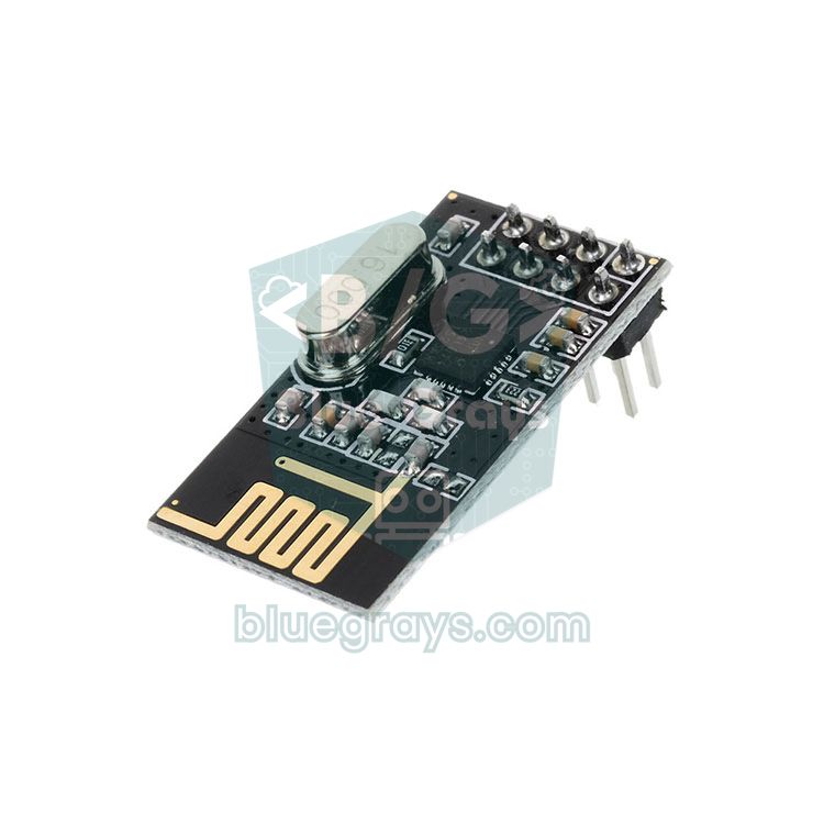
| Feature | 433MHz RF (FS1000A + XY-MK-5V) | nRF24L01 |
|---|---|---|
| Frequency | 433.92 MHz | 2.4 GHz |
| Modulation | ASK / OOK | GFSK |
| Direction | One-way (separate transmitter and receiver boards) | Two-way (one transceiver module) |
| Data rate | 1–4 kbps in practice (RadioHead default 2 kbps) | 250 kbps – 2 Mbps |
| Connection | A single data pin | SPI (7 wires) |
| Supply | Transmitter 3–12 V, receiver 5 V | 1.9–3.6 V |
| Error checking | In software (RadioHead CRC) | Hardware CRC, auto-acknowledge and retransmission |
| Range | 20–100 m with a 17.3 cm antenna | 50–100 m, ~1 km with the PA+LNA version |
| Wall penetration | Better (lower frequency) | Weaker |
| Works with off-the-shelf devices | Socket, doorbell and sensor remotes | No |
| Price | Very cheap | Cheap |
In short, if you need to send one-way, infrequent, small pieces of data (a button, a temperature value, the fact that a door has opened) or work with off-the-shelf sockets and sensors, the 433MHz module is the cheapest and simplest solution. For an RC car, a joystick or multi-node sensor networks that need fast, two-way, acknowledged communication, the nRF24L01 is the better choice. If you need a range of kilometres, look at LoRa modules; to see all the options side by side, read Arduino wireless communication modules.
433MHz RF module project ideas
- Wireless doorbell: play a melody inside the house when the button at the garden gate sends a signal; a buzzer is enough for the sound.
- Controlling sockets from an Arduino: clone the codes of remote-controlled sockets and switch lamps on and off by time or light level.
- Wireless door sensor: put a reed switch and a small Arduino with a transmitter on the door; when the door opens, the receiving side sounds an alarm.
- Home alarm system: build an Arduino alarm system that gathers off-the-shelf 433MHz PIR and door sensors in one central unit.
- Garden sensor station: send soil moisture or temperature to the house every few minutes with a battery-powered transmitter.
- 433MHz to Wi-Fi bridge: control every 433MHz device in your home from your phone and smart home system with an ESP32.
Common mistakes and how to fix them
| Symptom | Likely cause | Fix |
|---|---|---|
| No packets reach the receiver (RadioHead) | Speed or pins differ between the two sides, no antenna | Use the same constructor on both sides (2000, 11, 12) and solder a 17.3 cm wire to both modules |
| It only works a few centimetres apart | No antenna, or low voltage on the transmitter | Add an antenna and power the transmitter from 5–12 V |
| multiple definition of `__vector_11' error | RadioHead and the Servo library can't share Timer1 | Use RH_ASK_ARDUINO_USE_TIMER2 or ServoTimer2 |
| PWM on D9 and D10 doesn't work, the device on D10 behaves oddly | RH_ASK uses Timer1 and D10 (PTT) | Leave these pins free or choose another PTT pin in the constructor |
| RCSwitch shows no codes at all | The receiver's DATA is on a pin without an interrupt | Use D2 or D3 on the Uno and Nano |
| Codes you don't recognise appear on the screen | Neighbours' weather stations, sensors or noise | Only react to known codes, bit lengths and protocols |
| The cloned code doesn't switch the socket | Pulse length or protocol differs, or the remote uses rolling codes | Put the getReceivedDelay() value into setPulseLength() and raise the repeat count |
| The ESP32 receives no codes or behaves erratically | The 5 V receiver output is connected straight to a GPIO | Use a voltage divider or a 3.3 V receiver |
| Data drops out when a motor runs | Supply noise and voltage drops | Give the receiver a separate supply and add 100 nF + 10 µF capacitors |
433MHz RF modules give your projects a wireless arm for very little money, and they're among the few modules that can talk to the ready-made remote-controlled devices in your home. Once you understand the logic of wireless control, you can easily learn other methods such as IR remotes and Bluetooth. In the BlueGrays app you'll find projects such as communication between two Arduinos, switching a 220 V bulb with a remote, a door sensor with a reed switch and an ESP32 motion alarm, with circuit diagrams and step-by-step code.
Frequently asked questions
What is the range of a 433MHz RF module?
Without an antenna, a set only works over 1–3 metres. With a 17.3 cm wire antenna soldered to both sides and the transmitter powered from 5 V, 20–50 metres in open air is possible, and more than 100 metres with the transmitter at 9–12 V. Indoors, walls and interference reduce these figures noticeably.
How long should a 433MHz antenna be?
The most efficient simple antenna is a quarter-wave straight wire: about 17.3 cm for 433 MHz and 23.8 cm for 315 MHz. Solder the wire to the module's ANT pad and keep it straight and vertical; the receiver and transmitter antennas should point in the same direction.
Can a 433MHz transmitter and receiver communicate both ways?
With a single pair, communication only goes from the transmitter to the receiver. If you fit both a transmitter and a receiver on each side, you can work in both directions, and RadioHead's RHReliableDatagram class even adds acknowledgements and retries in that setup. Still, modules that are two-way from the start, such as the nRF24L01 or HC-12, are more practical for this.
Can a car or garage remote be cloned with a 433MHz module?
Car keys and modern garage remotes use rolling codes: the code changes with every press and a recorded code is rejected, so RCSwitch can't clone them. Fixed-code socket, doorbell and sensor remotes, however, can be cloned. Only use this method on your own devices; trying to access other people's systems leads to legal trouble.
Does a 433MHz RF module work with the ESP32?
Yes. You can power the FS1000A transmitter from 5 V and connect its DATA pin straight to a GPIO; a 3.3 V signal is enough. Because the XY-MK-5V receiver's output is 5 V, you should add a voltage divider or choose a receiver that runs on 3.3 V, such as the RXB6. The RCSwitch and RadioHead libraries both support the ESP32.
What is the difference between 433MHz and 315MHz modules?
Both versions are built the same way; only the operating frequency differs. In Europe and Turkey remotes mostly use 433.92 MHz, while 315 MHz is common in the US and some Asian countries. The transmitter and receiver, or the remote you want to clone, must be on exactly the same frequency.
Projects to build after reading this
See all projects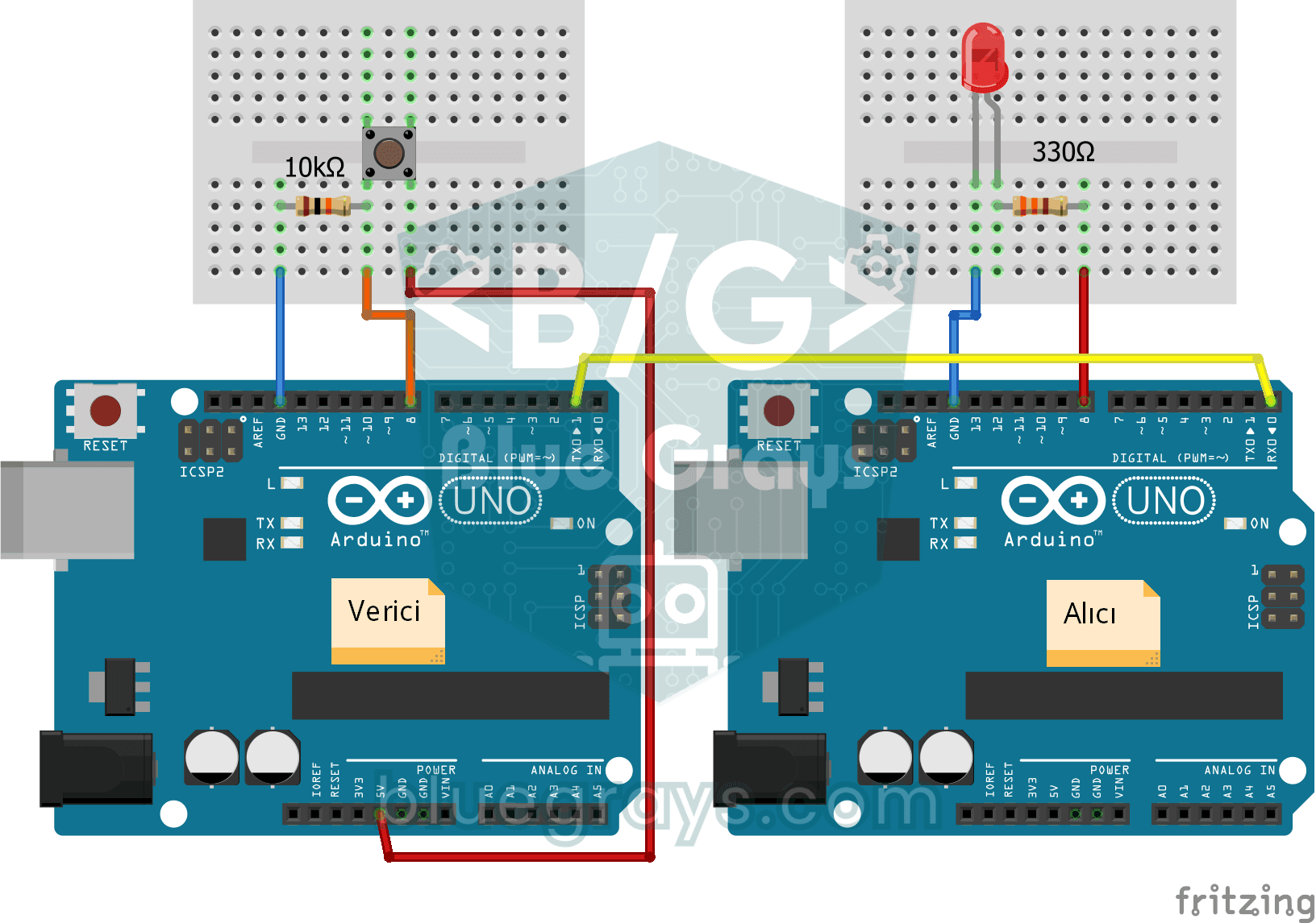
One-Way Communication Between 2 Arduinos
You get two Arduinos talking over a single wire: press the button on one and the LED on the other lights up, press it again and it goes off. The sending board reports the button press with a short mes
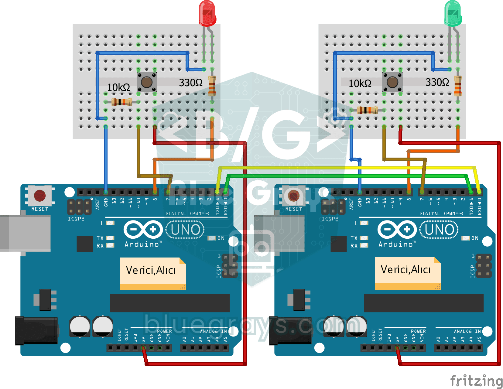
Two-Way Communication Between 2 Arduinos
Two Arduinos are wired together and talk to each other: press the button on one and the light on the other comes on, press it again and it goes off. Both boards run the same program, so each one both
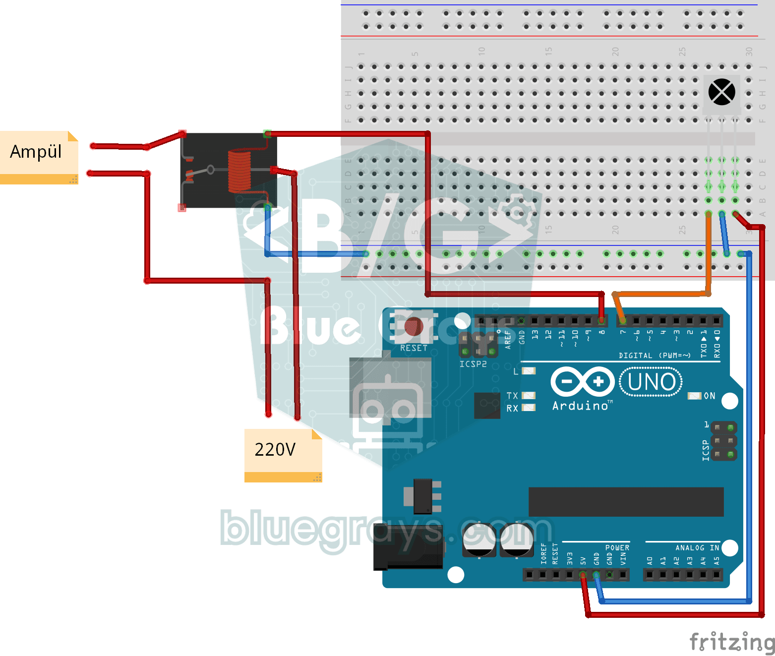
Lighting 220V Bulb with Remote Control
Switch a real light bulb in your home on and off with a TV remote, without getting up from the sofa. The Arduino reads the invisible light signal from the remote; the power button clicks the relay and
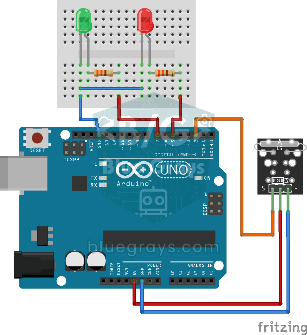
Reed Switch Door Sensor
Tell whether your door is open or closed just by looking at a light. You attach a small magnet to the door and a magnet-sensing switch to the frame; when the door is closed they sit side by side and t
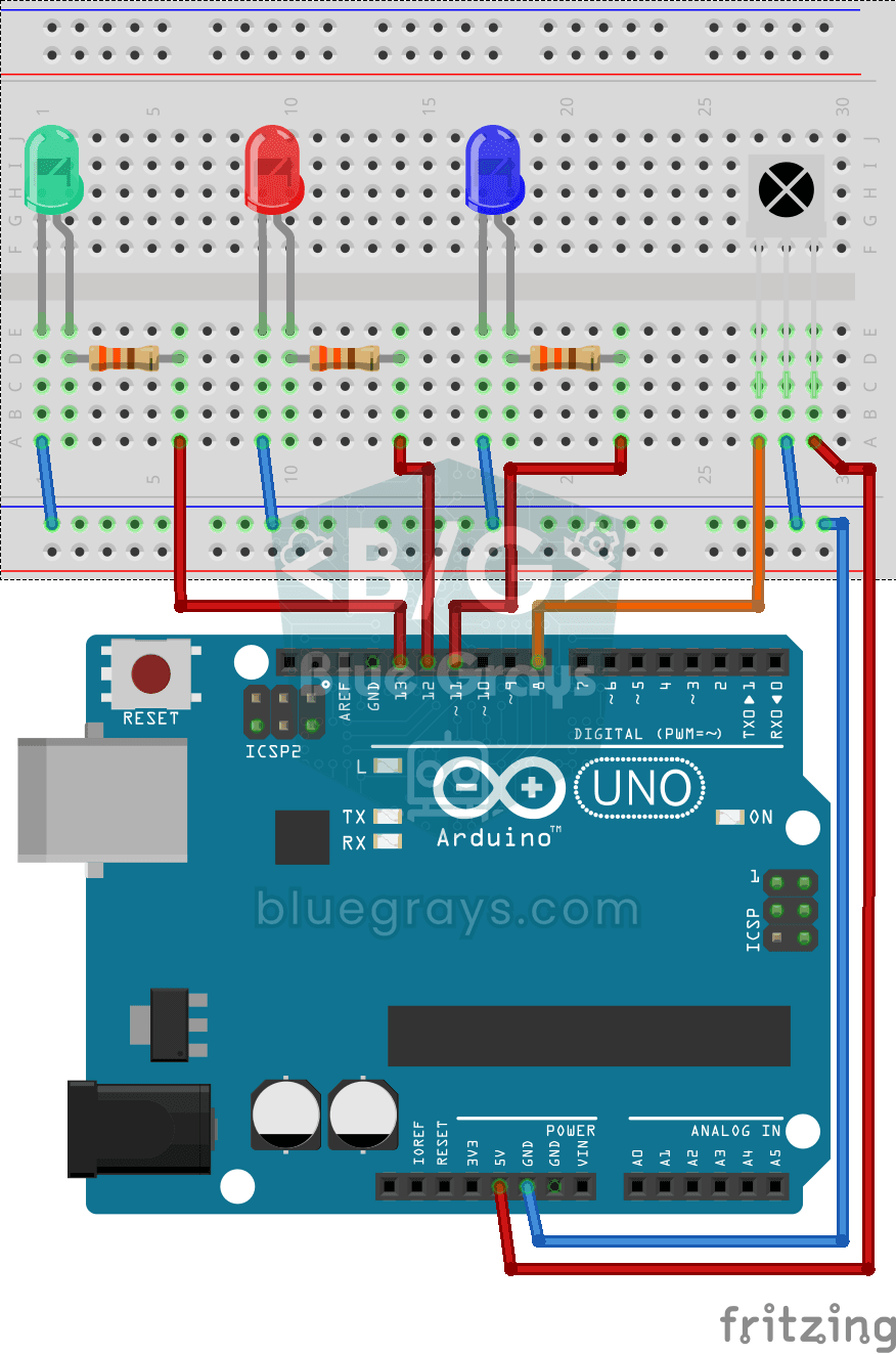
Led On/Off with IR Receiver and Remote Control
Like controlling three separate lamps without leaving your armchair: keys 1, 2 and 3 on the remote turn on the blue, red and green LEDs, and keys 4, 5 and 6 turn them off in the same order. The power

ESP32 IR Universal Remote (IR Receiver + Remote Control + 3 LEDs + Buzzer + OLED)
With the ESP32, you can read a standard IR remote control and use it to control your own device! In this project, we use an infrared receiver (NEC protocol, 38 kHz) to capture the signals from a 20-button IR remote. We’ve defined different actions for each button: buttons 1, 2, and 3 toggle three separate LEDs; the PWR button turns them all off; and the numbers 4–9 display special characters on the OLED. The SSD1306 OLED display shows the last button pressed in large font, along with a descripti
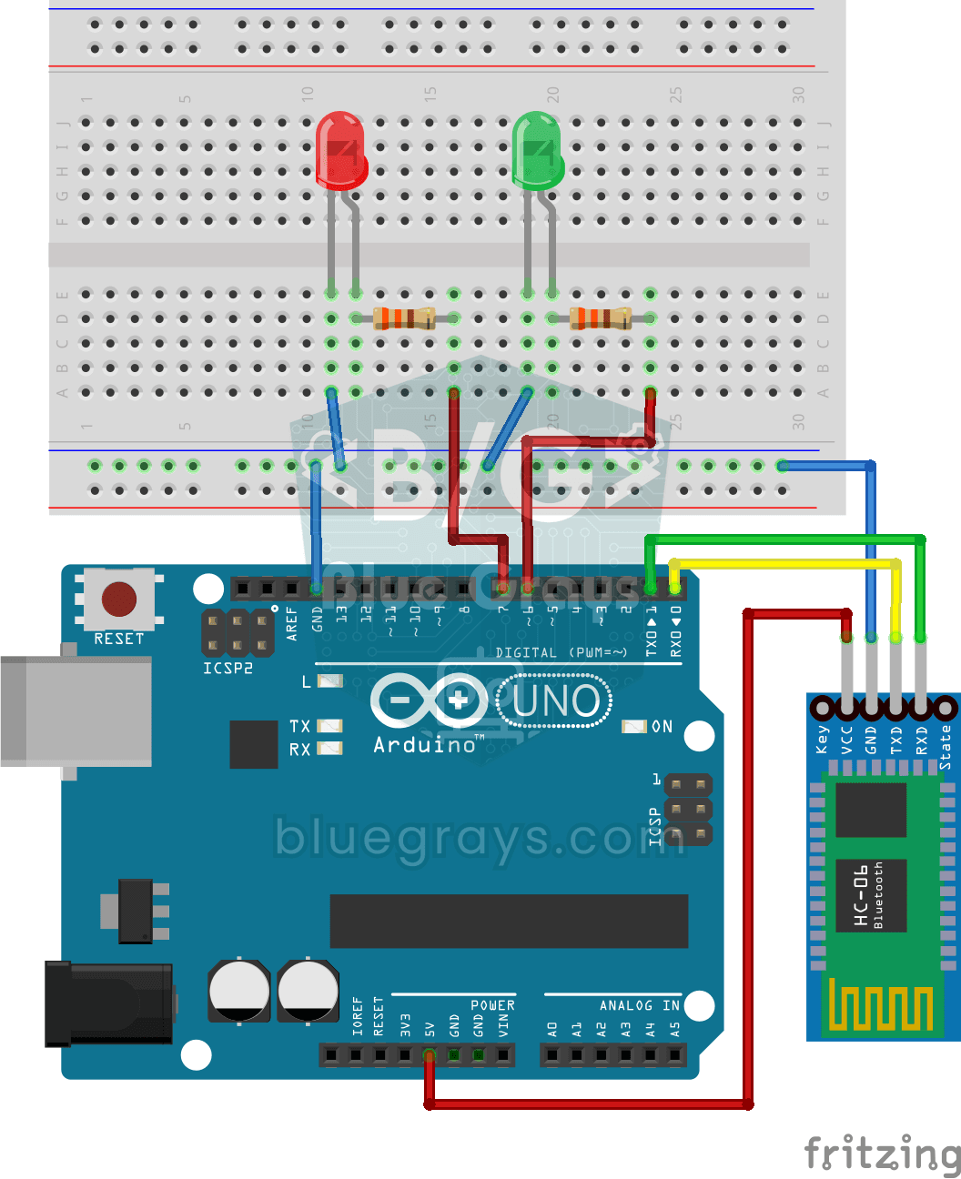
Control an LED from Your Phone via Bluetooth
A small rehearsal for switching the lights in your room on and off from your phone. The Bluetooth module passes the letters sent from your phone to the Arduino; one letter turns on the red LED, anothe