
Block Coding to MicroPython: Sensors and Raspberry Pi Pico
Block coding to MicroPython: read an LDR and HC-SR04 with blocks next to the C++, use the Serial Monitor, then switch to MicroPython on the Raspberry Pi Pico.
Going from block coding to MicroPython is easiest once you can read a sensor with blocks. Reading a sensor with blocks means getting a value without typing code: the "analog read A0" block grabs the light level from an LDR, and the "serial print" block sends that number to the Serial Monitor on your computer. In this article you'll first read sensors with blocks on Arduino using the LDR and HC-SR04 projects, comparing each block with its analogRead(), Serial.begin(), Serial.println() and pulseIn() line. Then you'll take the step from blocks to MicroPython on the Raspberry Pi Pico and see what changes when the same blocks become Python code.
So far every program in the series made something happen in the outside world: we lit LEDs, checked a button and built a counter with a loop. Reading a sensor works the other way round: the board measures the world and you get to see the number. That's why the serial port joins in here, since the easiest way to understand what a sensor measures is to watch its value on your screen. In the second half, the Raspberry Pi Pico block coding projects map to MicroPython instead of C++. Every project used here is free in BlueGrays, and the code quoted below is exactly the project code.
What reading a sensor means: digital and analog inputs
A button only reports two states: pressed or not. You read it with the digital pin read block (digitalRead) and the result is 0 or 1. Parts such as an LDR, a potentiometer or a soil moisture sensor give you every value in between: the voltage on the pin changes smoothly between 0 and 5 V. The circuit that turns this voltage into a number is the ADC (analog-to-digital converter). The Arduino Uno's ADC is 10-bit, so it splits the voltage into 1024 steps and returns a number from 0 to 1023; each step is about 4.9 mV. The ESP32 and the Pico have 12-bit ADCs that run at 3.3 V. This difference between boards is one of the most common sources of confusion when moving from blocks to code; you'll find the details in the ADC and analog-to-digital conversion article.
| Board | ADC | Value range | Reference voltage | Code |
|---|---|---|---|---|
| Arduino Uno | 10-bit | 0–1023 | 5 V | analogRead(A0) |
| ESP32 | 12-bit | 0–4095 | About 3.3 V | analogRead(34) |
| Raspberry Pi Pico | 12-bit (scaled to 16-bit by read_u16) | 0–65535 | 3.3 V | ADC(26).read_u16() |
Reading an LDR with blocks on Arduino
Our first example is the Measuring Light Intensity with an LDR project. An LDR is a resistor whose resistance drops as the light gets brighter; on its own it doesn't produce a voltage. To measure it, we put it in series with a fixed 10 kΩ resistor to build a voltage divider and connect the midpoint to A0. With the wiring below, the LDR sits on the 5V side, so more light means a higher voltage on A0 and a bigger reading; swap the LDR and the resistor and the direction flips. You can work out the divider output for different LDR values with the voltage divider calculator, and see how many ohms an LDR has in the dark and in bright light in the LDR light sensor article. We'll use the Pico column of the table in the MicroPython example near the end.
| Connection | Arduino Uno | Raspberry Pi Pico |
|---|---|---|
| LDR leg 1 | 5V | 3V3(OUT), physical pin 36 |
| LDR leg 2 + one end of the 10 kΩ (midpoint) | A0 | GP26 / ADC0, physical pin 31 |
| Other end of the 10 kΩ | GND | GND, physical pin 38 (or AGND, pin 33) |
| Reading range | 0–1023 | 0–65535 |
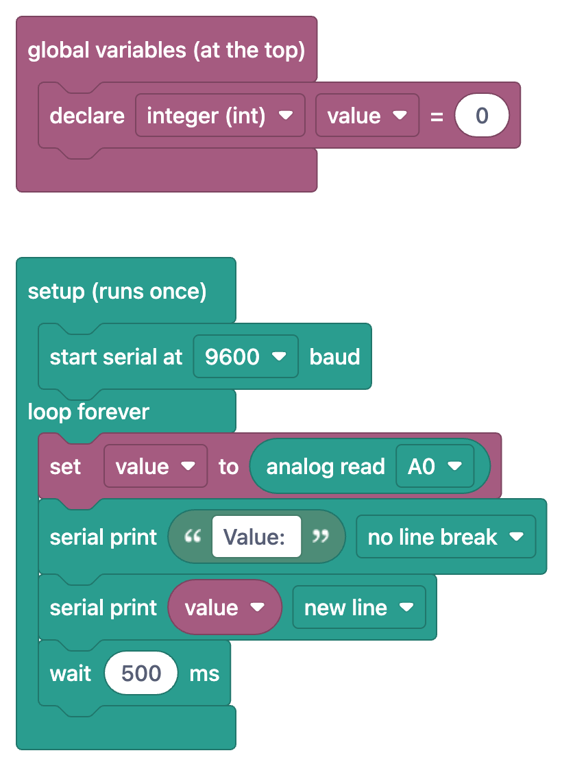
Read the blocks from top to bottom. The "declare integer (int) value = 0" block inside global variables (at the top) is the int value; line at the top of the code. The setup (runs once) section holds a single block, "start serial at 9600 baud", which is Serial.begin(9600);. Inside loop forever, "set value to analog read A0" comes first; that's the value = analogRead(A0); line. Then there are two "serial print" blocks. The first prints the text "Value:" with the no line break option and becomes Serial.print(); the second prints value with the new line option and becomes Serial.println(). That way each measurement shows up as a single line such as "Value: 512". The last block, "wait 500 ms", is delay(500);, so you get two readings per second. To turn the reading into a voltage, use value × 5.0 / 1023: 512 is roughly 2.5 V. In a dark room the value drops to a few hundred, and with a flashlight on the LDR it climbs above 900; the exact numbers depend on your LDR and the room.
1int value;   // Işık değeri / Light reading (0-1023)
2
3void setup() {
4  Serial.begin(9600);   // Seri port 9600 baud / Serial at 9600 baud
5}
6
7void loop() {
8  value = analogRead(A0);   // LDR gerilimini oku / Read the LDR voltage
9  Serial.print("Value: ");
10  Serial.println(value);
11  delay(500);               // 0,5 sn bekle / Wait 0.5 s
12}Opening the Serial Monitor and watching the values
- Paste the code into the Arduino IDE, select your board and port, then click Upload.
- When the upload finishes, click the magnifier icon at the top right or open Tools > Serial Monitor (shortcut Ctrl+Shift+M).
- Set the Serial Monitor's baud rate box to the value in the code: 9600 baud for this project.
- A "Value: …" line scrolls by every half second. Cover the LDR with your hand and watch the number drop.
- To see the change as a graph, open Tools > Serial Plotter; the same data is drawn as a timeline.
- Line ending settings and sending data from the Serial Monitor to the board are covered in detail in the Arduino Serial Monitor article.
Distance with the HC-SR04: the µs wait and pulse length blocks
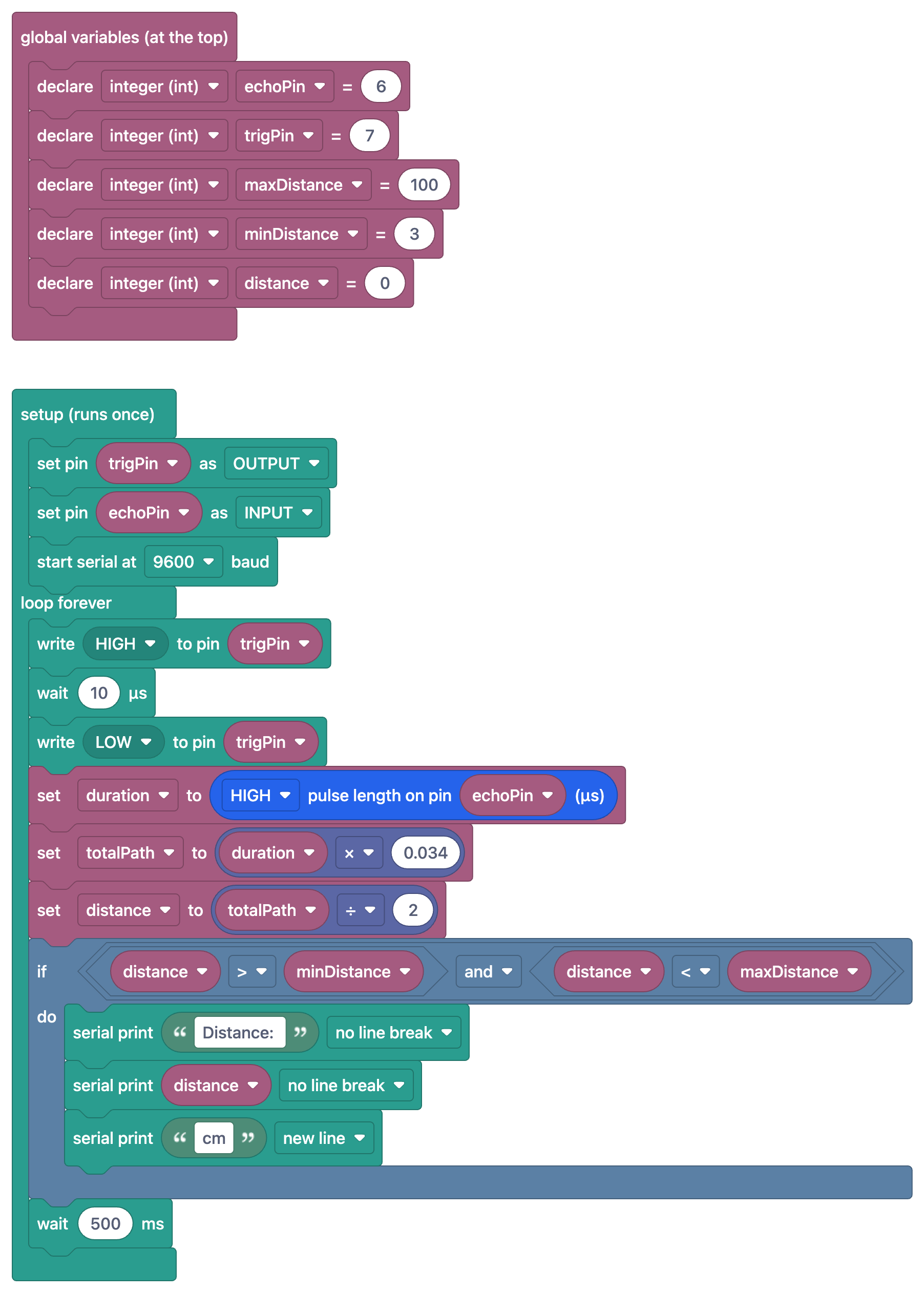
The second sensor project is HC-SR04 Distance Measurement (Serial Display). It adds two new blocks. The trio that starts with "write HIGH to pin trigPin" tells the sensor to send a burst of sound: the "wait 10 µs" block in the middle is delayMicroseconds(10);, a wait a thousand times shorter than "wait … ms". Next comes "set duration to HIGH pulse length on pin echoPin (µs)", which is the unsigned long duration = pulseIn(echoPin, HIGH); line and measures how many microseconds the Echo pin stays HIGH. Sound travels through air at about 0.034 cm/µs, and that time covers the round trip. So "set totalPath to duration × 0.034" calculates the whole path and "set distance to totalPath ÷ 2" the one-way distance. A 1000 µs pulse, for example, means a 34 cm path, so the object is 17 cm away; since distance is an int, the decimals are dropped. Finally, the block "if distance > minDistance and distance < maxDistance" becomes if (distance > minDistance && distance < maxDistance) and only prints readings between 3 and 100 cm. If the sensor gets no echo, pulseIn() returns 0, and this check keeps those bogus zeros off the screen as well. In the code the pins are trigPin = 7 and echoPin = 6. For the sensor's range and accuracy, see the HC-SR04 distance sensor article.
Same idea on the ESP32: a 12-bit ADC
The ESP32 version of the same LDR logic is the Reading Light Intensity with the ESP32 LDR Module project. The blocks still map to C++ and read just like on Arduino, with three differences. First, setup() locks the ADC to 12 bits with analogReadResolution(12), so analogRead() returns 0–4095 instead of 0–1023, and a threshold written for Arduino such as "dark below 500" doesn't mean the same thing on the ESP32. Second, the serial port runs at 115200 baud instead of 9600, so set the Serial Monitor to 115200 as well. Third, on the LDR module's AO output the voltage and the raw value drop as the light gets brighter. That's why the code uses the calibration values RAW_DARK = 4000 and RAW_LIGHT = 100, keeps the reading in that range with constrain() and turns it into 0% for dark and 100% for bright with map(). On a classic ESP32 DevKit the LDR goes to GPIO 34, an input-only pin on ADC1. Since ADC2 pins can't be read while Wi-Fi is on, wiring analog sensors to ADC1 pins is a good habit. For the board's general features, see What is the ESP32.
From blocks to MicroPython on the Raspberry Pi Pico
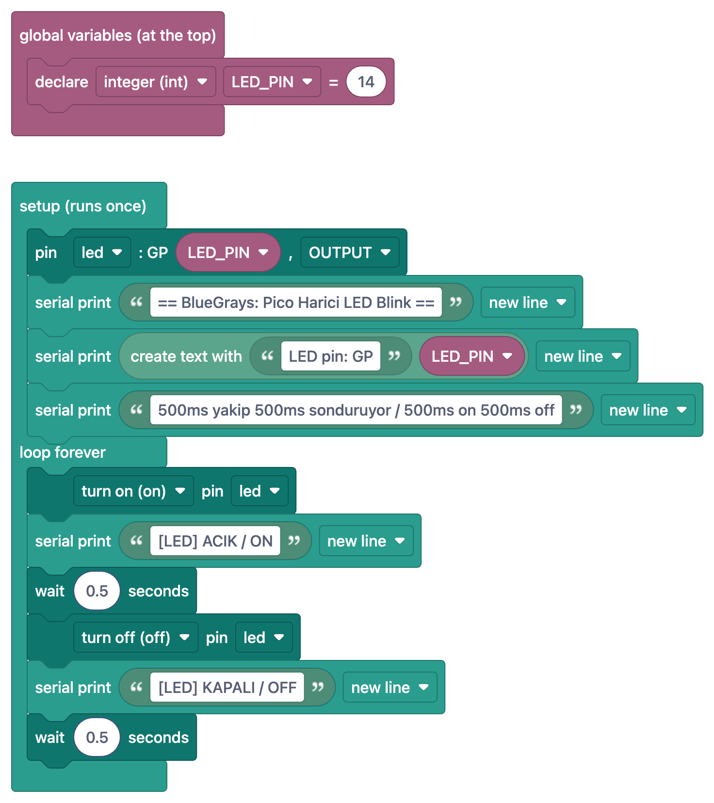
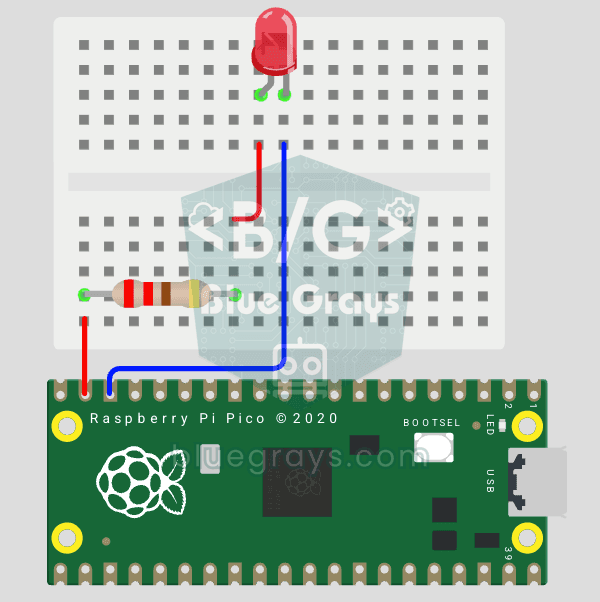
In Pico projects the blocks map to MicroPython instead of C++. The blocks look familiar, but the language underneath is different: no curly braces or semicolons, code blocks are marked by indentation, and there are no setup() or loop() functions. Let's make the switch with the simplest project, Raspberry Pi Pico: Controlling an External LED (GP14 + Breadboard). The circuit is tiny: GP14 (physical pin 19) goes through a 220–330 Ω resistor to the LED's long leg, and the LED's short leg goes to GND (for example physical pin 18). The program turns the LED on for half a second, off for half a second, and prints a line to Thonny's Shell at each step. If the Pico is new to you, start with What is the Raspberry Pi Pico.
1from machine import Pin
2import time
3
4# ============ PIN / PIN ============
5LED_PIN = 14                    # Boştaki herhangi bir GPIO / Any free GPIO
6led = Pin(LED_PIN, Pin.OUT)
7
8print("== BlueGrays: Pico Harici LED Blink ==")
9print("LED pin: GP" + str(LED_PIN))
10print("500ms yakip 500ms sonduruyor / 500ms on 500ms off")
11
12# ============ ANA DÖNGÜ / MAIN LOOP ============
13while True:
14    led.on()                    # LED'i yak / Turn the LED on
15    print("[LED] ACIK / ON")
16    time.sleep(0.5)
17
18    led.off()                   # LED'i söndür / Turn the LED off
19    print("[LED] KAPALI / OFF")
20 time.sleep(0.5)| Block | MicroPython | Note |
|---|---|---|
| global variables (at the top) → declare integer (int) LED_PIN = 14 | LED_PIN = 14 | Python has no type names; the word int doesn't appear in the code |
| setup (runs once) | Every line before while True | There's no separate setup(); the file runs once from top to bottom |
| pin led : GP LED_PIN, OUTPUT | led = Pin(LED_PIN, Pin.OUT) | Pin comes from the from machine import Pin line |
| serial print "…" new line | print("…") | print() always adds a line break |
| create text with "LED pin: GP" LED_PIN | "LED pin: GP" + str(LED_PIN) | A number can't be added to text until str() turns it into text |
| loop forever | while True: | The lines inside are indented by 4 spaces |
| turn on (on) pin led | led.on() | Sets the pin to 3.3 V, the LED lights up |
| wait 0.5 seconds | time.sleep(0.5) | The time is in seconds; 500 ms = 0.5 |
| turn off (off) pin led | led.off() | Sets the pin to 0 V, the LED goes off |
Four things stand out in that table. First, the from machine import Pin and import time lines have no block; in Python you import the modules you need at the top, and the blocks assume that for you. Second, Arduino's "start serial at 9600 baud" block has no counterpart here: on the Pico, print() output goes straight over USB to Thonny's Shell, with no baud rate to set. Third, the unit of waiting has changed: on Arduino "wait 500 ms" is delay(500), while on the Pico "wait 0.5 seconds" is time.sleep(0.5). Fourth, and most important, indentation: every block that sits inside the "loop forever" block is written four spaces in under the while True: line. Delete a line's indentation and that line falls out of the loop; in Python, spaces do the job that curly braces do in C++. You'll find the other core rules of MicroPython in the MicroPython basics article.
The same operations in three languages: blocks, C++ and MicroPython
| Operation | Block | Arduino C++ | MicroPython (Pico) |
|---|---|---|---|
| Runs once | setup (runs once) | void setup() { … } | Lines before while True |
| Repeat forever | loop forever | void loop() { … } | while True: (indented) |
| Variable | declare integer (int) LED_PIN = 14 | int LED_PIN = 14; | LED_PIN = 14 |
| Output pin | set pin … as OUTPUT / pin led : GP LED_PIN, OUTPUT | pinMode(14, OUTPUT); | led = Pin(14, Pin.OUT) |
| Turn the LED on | write HIGH to pin … / turn on (on) pin led | digitalWrite(14, HIGH); | led.on() |
| Wait | wait 500 ms / wait 0.5 seconds | delay(500); | time.sleep(0.5) |
| Short wait | wait 10 µs | delayMicroseconds(10); | time.sleep_us(10) |
| Analog read | analog read A0 | analogRead(A0) → 0–1023 | ADC(26).read_u16() → 0–65535 |
| Start serial | start serial at 9600 baud | Serial.begin(9600); | Not needed |
| Print with a new line | serial print … new line | Serial.println(x); | print(x) |
| Print, same line | serial print … no line break | Serial.print(x); | print(x, end="") |
| Join text | create text with | Two separate Serial.print() calls | "LED pin: GP" + str(x) |
Your own example: reading an LDR on the Pico with MicroPython
Now let's move the Arduino LDR project to the Pico. The wiring follows the Pico column of the table above: one LDR leg to the 3V3(OUT) pin, the other leg to both GP26 and one end of the 10 kΩ resistor, and the other end of the resistor to GND. The Pico has three pins that can read analog values: GP26 (ADC0), GP27 (ADC1) and GP28 (ADC2). In MicroPython you create an ADC(26) object and call read_u16(); although the Pico's ADC is 12-bit in hardware, this function scales the result to 0–65535. To get the voltage, multiply the value by 3.3 and divide by 65535. The program follows the same flow as the Arduino version: measure, print, wait half a second. On top of that we added a threshold: when the room gets dark, the onboard LED turns on. Thinking in blocks, the lines before while True are the "setup (runs once)" section, while True: is "loop forever", the if/else is the if block from part 3 of the series, led.on() is "turn on (on) pin led", time.sleep(0.5) is "wait 0.5 seconds", and the + str() inside print() is the "create text with" block. The ADC(26).read_u16() line does the job of Arduino's "analog read A0" block. Tune THRESHOLD to the numbers you see in the Shell in your own room.
1from machine import Pin, ADC
2import time
3
4# ============ PIN / PIN ============
5ldr = ADC(26)                   # GP26 = ADC0, bölücünün orta noktası / divider midpoint
6led = Pin(25, Pin.OUT)          # Dahili LED; Pico W'de Pin("LED") / Onboard LED; Pico W: Pin("LED")
7THRESHOLD = 20000               # Karanlık eşiği, odana göre ayarla / Darkness threshold, tune for your room
8
9print("== BlueGrays: Pico LDR ==")
10
11# ============ ANA DÖNGÜ / MAIN LOOP ============
12while True:
13    value = ldr.read_u16()                      # 0-65535
14    voltage = value * 3.3 / 65535               # Volt / Volts
15    print("Value: " + str(value) + "  Voltage: " + str(round(voltage, 2)) + " V")
16
17    if value < THRESHOLD:                       # Az ışık = küçük değer / Little light = small value
18        led.on()
19    else:
20        led.off()
21
22    time.sleep(0.5)                             # 0,5 sn = 500 ms / 0.5 s = 500 ms
Uploading to the Pico with Thonny and main.py
- Install Thonny on your computer. If the Pico doesn't have MicroPython yet, hold the BOOTSEL button while plugging in the USB cable; Thonny offers to install MicroPython on the first connection.
- In Thonny's bottom right corner, choose MicroPython (Raspberry Pi Pico) as the interpreter. If you see the >>> prompt in the Shell at the bottom, you're connected.
- Copy the project code from BlueGrays and paste it into Thonny's editor.
- Click the green Run button or press F5. The code runs on the Pico and the print() output appears in the Shell. Use the Stop button (Ctrl+F2) to stop it.
- If you want the code to run without a computer, choose File > Save as, pick Raspberry Pi Pico in the dialog and name the file main.py. The Pico runs this file automatically every time it gets power, so a USB charger or a power bank is all you need.
- If Thonny doesn't see the board, check the cable and drivers in the order given in the Raspberry Pi Pico not recognized article.
More free Pico block projects
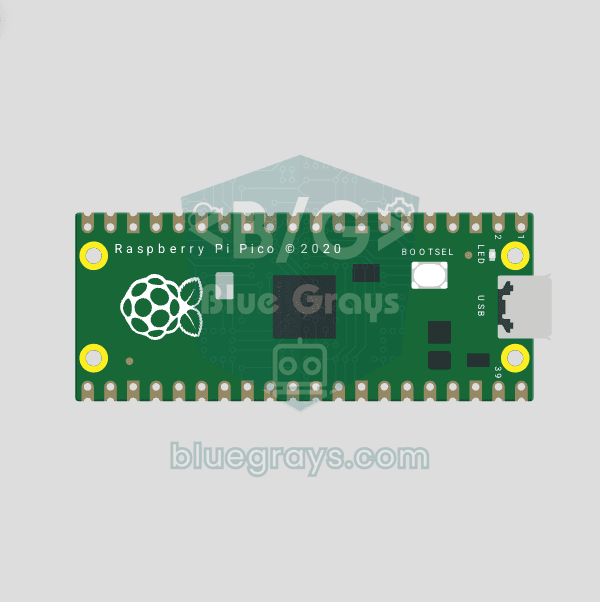
- Raspberry Pi Pico Onboard LED Blink (GP25): no wiring at all; it blinks the LED on the board with LED_PIN = 25. The code is almost identical to the project above, so open the two side by side and you'll see that only the pin number changes. On the Pico W the onboard LED is wired to the Wi-Fi chip, so you use Pin("LED").
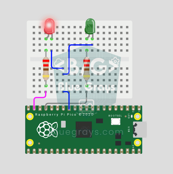
- Raspberry Pi Pico Alternating Two LEDs (GP14 + GP13): it starts from opposite states with led1.value(1) and led2.value(0), then calls toggle() on both LEDs in the loop. Because the code says from time import sleep, the wait appears as sleep(0.5) instead of time.sleep(0.5).
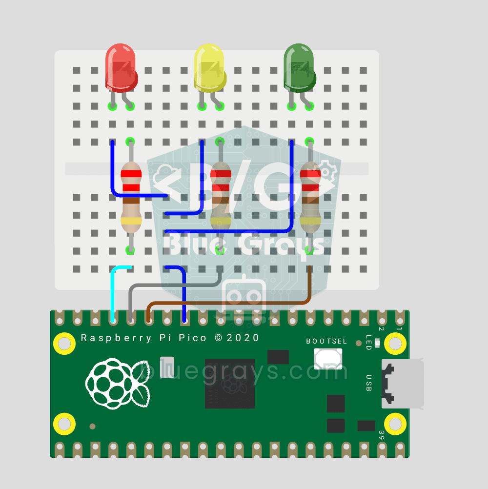
- Raspberry Pi Pico Traffic Light Simulator (GP11/GP12/GP13): a function called all_off() switches every LED off; green stays on for 4, yellow for 1.5 and red for 3 seconds, followed by a 1-second red+yellow starting phase.
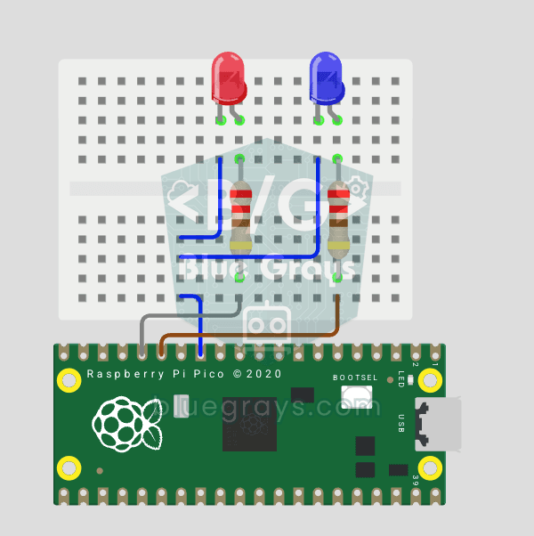
- Raspberry Pi Pico Police Strobe Light Effect (GP11 + GP12): this time the wait is in milliseconds with sleep_ms(WAIT_MS), where WAIT_MS = 300. Seeing the seconds and milliseconds functions side by side in two projects is the best way to avoid the most common mistake below.
Common mistakes and how to fix them
| Mistake | Symptom | Fix |
|---|---|---|
| Writing time.sleep(500) | The LED turns on and stays that way for over 8 minutes | In MicroPython the time is in seconds: write time.sleep(0.5) or time.sleep_ms(500) |
| Shifting the indentation | IndentationError, or lines that don't run in the loop | Start every line under while True: with the same 4 spaces and don't mix tabs and spaces |
| Adding a number to text without str() | TypeError: can't convert 'int' object to str implicitly | Write "LED pin: GP" + str(LED_PIN) |
| Feeding 5 V to a Pico ADC pin | Wrong readings and a risk of permanent damage | The Pico uses 3.3 V logic; power the divider from the 3V3(OUT) pin |
| Copying an Arduino threshold to the Pico | The "value < 500" condition always gives the same result | Account for the range: Uno 0–1023, ESP32 0–4095, Pico read_u16() 0–65535 |
| Serial Monitor baud rate doesn't match | Garbage characters | Match the monitor to the rate in the code: 9600 or 115200 |
| Using an ADC2 pin on the ESP32 | Readings stop working once Wi-Fi is on | Wire analog sensors to ADC1 pins such as GPIO 32–39 |
| Not saving the file as main.py | The code runs from Thonny but not after unplugging USB | Save the file to the Pico as main.py |
Keep going with blocks in the BlueGrays app
Every project in this article is free in the BlueGrays app. Turn on the Show as blocks switch in a project's code section and the code is replaced by the same program as blocks; tap the image to open it full screen. The Understand the blocks tab walks you through the program step by step, showing only the blocks for each step and what they do. That's where you can see exactly what the pulse length block measures in the HC-SR04 project, or why the setup part of a Pico project comes before while True. All the Arduino and MicroPython command examples in the Code guide are shown as blocks too. To test what you've learned, Daily questions gives you 5 questions a day from A1 to C2, a weekly leaderboard and badges. Keep in mind that blocks are never uploaded to the board directly: the board always gets the project's real code, which you copy into the Arduino IDE for Arduino and ESP32 or into Thonny for the Pico. You can filter the project list for projects with the block badge and find every block project for Arduino, ESP32 and Pico on the block coding page.
With the serial port and sensor reading under your belt, you can now read every basic part of a project both as blocks and as code. The last part of the series takes these steps into the classroom: a robotics coding lesson plan with block coding for teachers. Until then, you can go through the circuit diagrams and code of the LDR, HC-SR04 and Pico LED projects step by step in the BlueGrays app, switch to the block version of the same program with Show as blocks, and follow what each step does with Understand the blocks.
Frequently asked questions
How do I move from block coding to MicroPython?
The easiest way is to look at a program's blocks and its MicroPython code side by side. Once you've seen in a few projects that "loop forever" is while True:, "turn on (on) pin led" is led.on() and "wait 0.5 seconds" is time.sleep(0.5), you start reading the code without the blocks. Then edit the code yourself with small changes such as the wait time or the pin number.
Can you program a Raspberry Pi Pico with block coding?
In BlueGrays, 10 Pico projects come with a block version, and those blocks map one to one to MicroPython code; 5 of them are completely free. What goes onto the board is the project's MicroPython code, not the blocks: you paste it into Thonny and run it. That way you understand the logic with blocks and program the board with real code.
Why does Arduino analogRead return values from 0 to 1023?
The Arduino Uno's ADC is 10-bit and splits the 0–5 V range into 1024 steps. 0 V reads as 0 and 5 V as 1023, with each step about 4.9 mV. To turn a reading into a voltage, use value × 5.0 / 1023.
Why does read_u16 go up to 65535 on the Raspberry Pi Pico?
The Pico's ADC is 12-bit in hardware, but MicroPython's read_u16() scales the result to 16 bits so that the range is the same across different boards. So 0 V reads as 0 and 3.3 V as about 65535. Any threshold you bring over from Arduino has to be recalculated for this range.
Is time.sleep in MicroPython in seconds or milliseconds?
time.sleep() works in seconds: time.sleep(0.5) waits half a second. For milliseconds use time.sleep_ms(500), and for microseconds time.sleep_us(10). If you mix it up with Arduino's delay(500) and write time.sleep(500), the program waits for more than 8 minutes.
How do I make my Thonny code run permanently on the Pico?
Save the code to the Raspberry Pi Pico as main.py with File > Save as. The Pico runs main.py automatically every time it gets power, with no computer needed. If you only press Run, the code isn't saved on the Pico and won't run after a restart.
Projects to build after reading this
See all projects
Measuring Light Intensity with an LDR
Want to see how bright your room is as a number? The LDR, a small part that reacts to light, measures the light around it, and the Arduino writes the value to your computer screen every half second. C
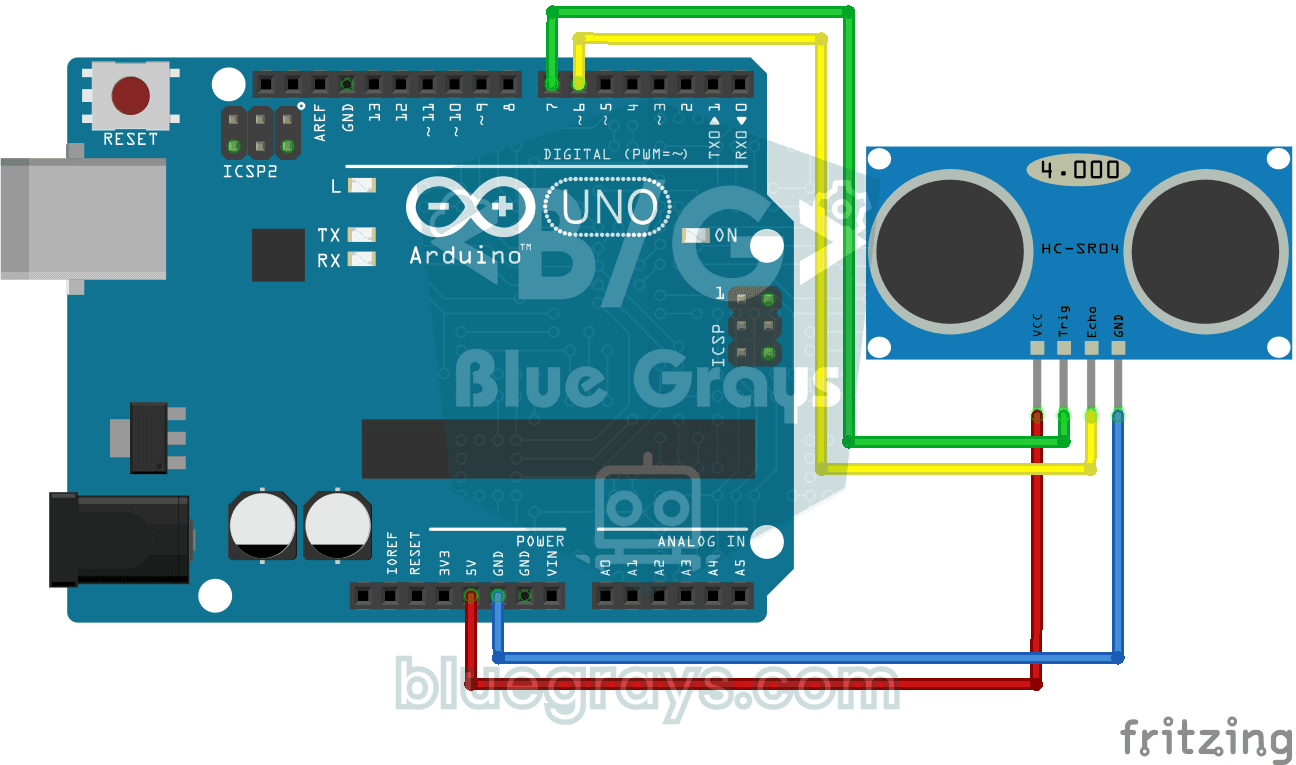
HC-SR04 Distance Measurement (Serial Display)
The HC-SR04 sensor works just like a bat finding its way in the dark: it sends out a sound you cannot hear, listens for the echo and measures how far away the object in front of it is. The Arduino wri

Reading Light Intensity with the ESP32 LDR Module
Real-time monitoring of the LDR module's raw ADC value and relative light percentage calculated from dark and light reference values in the Serial Monitor. This percentage is not a lux measurement. Teaches the module’s calibration logic. It is ideal to complete this before Project 10, as it is used to determine the threshold value.
Raspberry Pi Pico: Controlling an External LED (Breadboard)
The next step after Pico’s built-in LED: connecting an external LED to the breadboard and controlling it via the GP14 pin. In this project, you’ll learn how to use any of the Pico’s general-purpose GPIO pins as an output, the LED’s polarity (long leg = anode/+, short leg = cathode/–), and why a current-limiting resistor (220Ω) is required. If you don’t include the resistor, excessive current will flow through the LED and it may burn out. The circuit is very simple: Pico GP14 → 220Ω resistor → LE
Raspberry Pi Pico Onboard LED Blink (Pico and Pico W)
The opening project of the Raspberry Pi Pico series! We blink the green onboard LED to verify the board works — a classic "Hello World" first experiment. NO external components, just Pico and USB cable. Code is written in MicroPython (the official language backed by Raspberry Pi Foundation). Learn machine.Pin class, Pin.OUT mode, led.on()/off() methods, and time.sleep() in Thonny IDE. Follow every toggle live in the Serial (REPL) output. Also perfect to verify
Raspberry Pi Pico Alternating Two LEDs (Blink-Flip Pattern)
The next step after single LED on Pico: two LEDs blink alternately in a classic flip-flop pattern. When one turns off, the other lights up — the most basic example of multi-GPIO coordination. In this project two different color LEDs (red on GP14, green on GP13) swap states every 500ms. MicroPython's Pin.toggle() method makes the code short and clear. The same core logic is the foundation of traffic lights, police strobes, chasing LEDs and all multi-LED animations. Very simple circuit: 220Ω res
Raspberry Pi Pico Traffic Light Simulator (3 LEDs Sequential)
We simulate a real traffic light with red, yellow and green LEDs — the first 3-LED project of the Pico series! Green 4 sec "go", yellow 1.5 sec "ready", red 3 sec "stop" and red+yellow 1 sec "starting" (European traffic light pattern). Learn function definition (def all_off()), state machine logic (sequence) and multi-GPIO synchronization. Very simple circuit: 3 LEDs on GP11 (Green), GP12 (Yellow), GP13 (Red), each with a 220Ω current-limiting resistor. GP11-GP12-GP13 are ad
Raspberry Pi Pico Police Strobe Light Effect (Red + Blue)
We simulate a police car's light bar with a Raspberry Pi Pico in its simplest form! The red and blue LEDs take turns (flip-flop): while red is on, blue is off, and they swap every 0.3 seconds, forever. The code writes the two steps directly in a single while True loop; the speed is set with the WAIT_MS constant.