
Transistor Flip-Flop: Two-LED Flasher Circuit
The classic flip-flop circuit that everyone starting out in electronics builds: with two BC547 transistors, two capacitors and four resistors, two LEDs flash in turn. No IC, no code. The real name of this circuit is the astable multivibrator; the transistors turn each other off in turn. You see how a capacitor silences a transistor and how the time is set by R × C.
Video
Circuit Diagram
Breadboard Layout
Build Steps
- 1
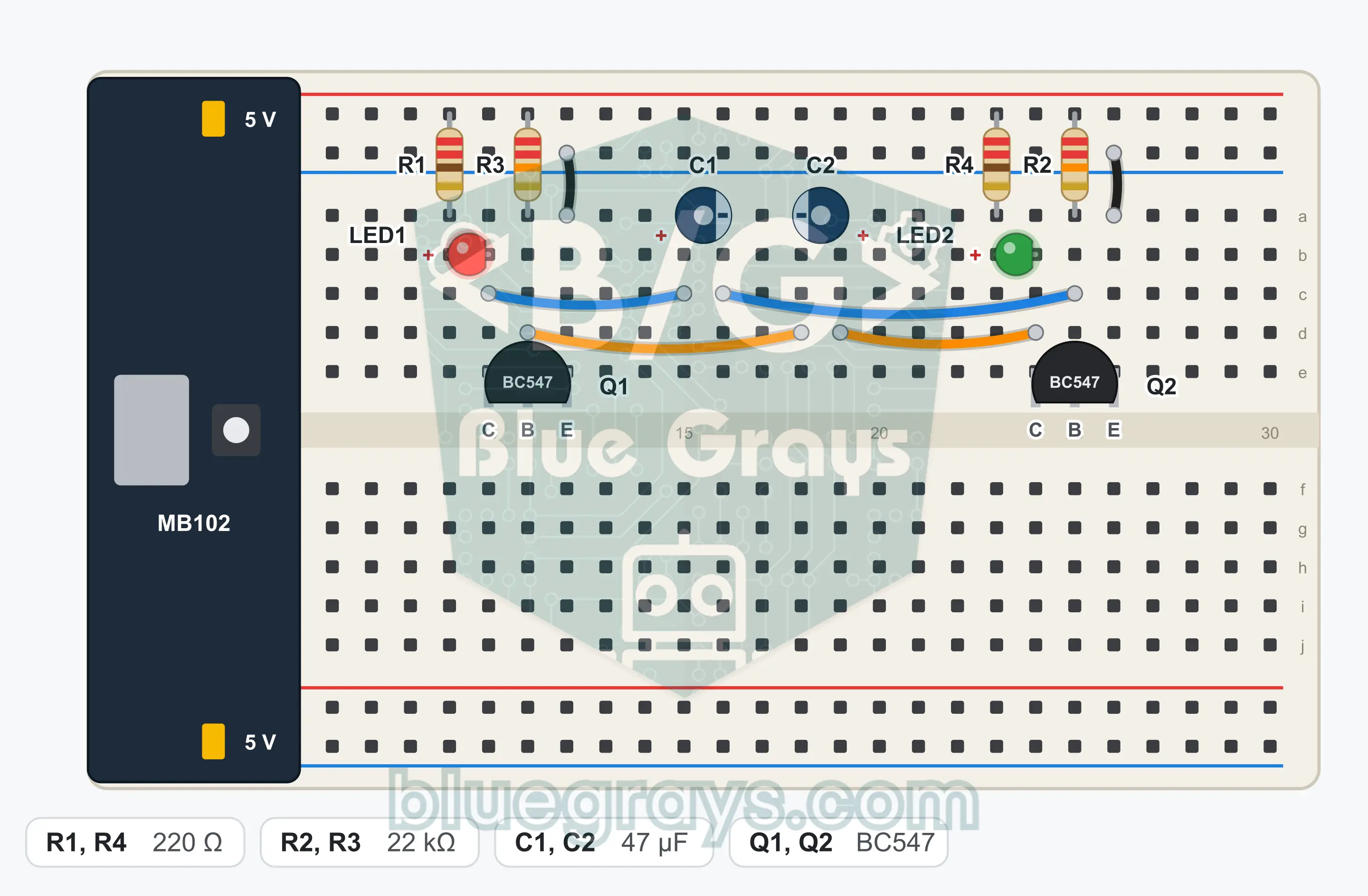
Plug the MB102 power module onto the end of the breadboard and set both jumper caps to the 5 V position. Leave the module's switch off for now.
- 2
Plug in Q1 (BC547) with its flat face toward you, so that its three legs land in three separate rows. From left to right the legs are collector, base, emitter.
- 3
Plug in Q2 (BC547) a few rows to the right of Q1, facing the same way.
- 4
Connect the emitter of Q1 to the GND (−) rail with a jumper wire.
- 5
Connect the emitter of Q2 to the GND rail with a jumper wire.
- 6
Fit R1 (220 Ω): one end into the + rail, the other end into an empty row.
- 7
Fit LED1 (red): long leg (anode) into the row of R1's free end, short leg (cathode) into the collector row of Q1.
- 8
Fit R4 (220 Ω): one end into the + rail, the other end into an empty row.
- 9
Fit LED2 (green): long leg (anode) into the row of R4's free end, short leg (cathode) into the collector row of Q2.
- 10
Fit R2 (22 kΩ) between the + rail and the base of Q2.
- 11
Fit R3 (22 kΩ) between the + rail and the base of Q1.
- 12
Fit C1 (47 µF): long leg (positive) into the collector row of Q1, the short leg on the striped side (negative) into the base row of Q2.
- 13
Fit C2 (47 µF): long leg (positive) into the collector row of Q2, the short leg on the striped side (negative) into the base row of Q1.
- 14
Compare the connections with the schematic, then switch on the power module.
Tip: keep the battery or power supply disconnected while wiring.
Test Steps
- 1
Switch on the power module: the LEDs must start flashing in turn. If both stay lit together, switch the power off and on again.
- 2
Count 10 flashes of the red LED: it must take about 11 to 14 seconds.
- 3
Observe that only one LED is at full brightness at a time. A very short overlap at the moment of transition is normal.
- 4
Switch the power off and on: the circuit must restart by itself every time.
How It Works
Two BC547s turn each other off in turn through cross-coupled capacitors; the red and green LEDs swap places about every 0.6 seconds. The time is set by the 22 kΩ resistors and the 47 µF capacitors.
Two switches, cross-coupled
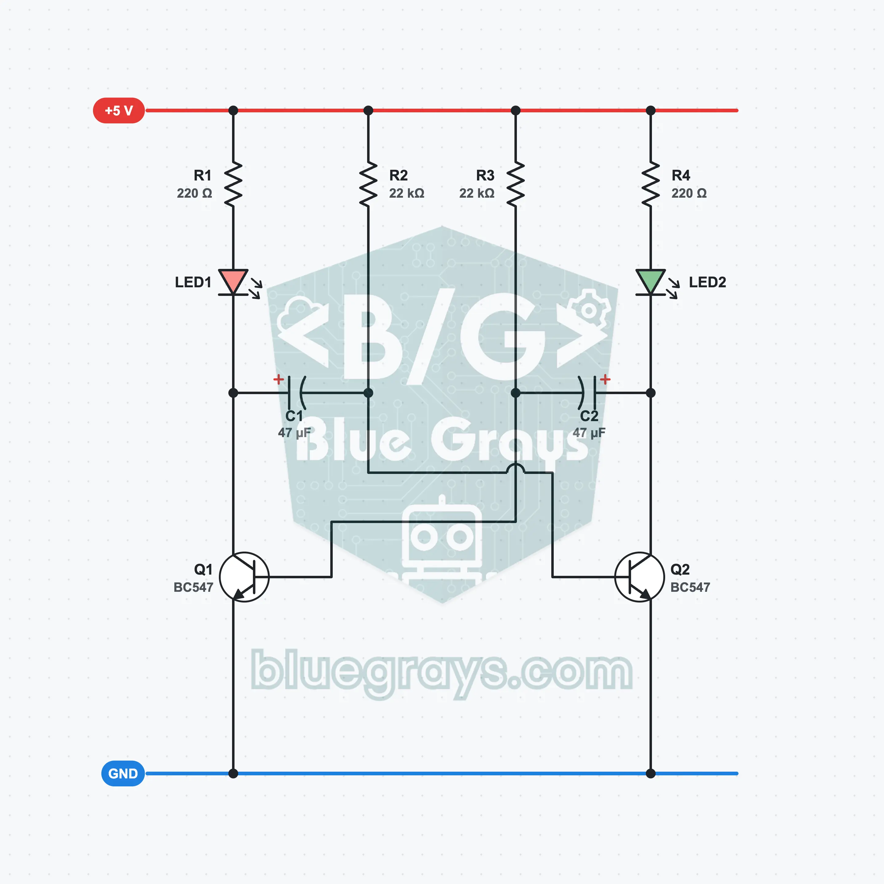
Each transistor is a switch that lights its own LED. LED1 lights while Q1 is conducting, LED2 while Q2 is conducting. The trick is the capacitors: the collector of each transistor goes to the base of the other through a capacitor.
How does one transistor turn the other off?
When Q1 turns on, its collector drops from about 3.3 V to 0 V. Because the voltage across C1 cannot change in an instant, its other end, that is, the base of Q2, is pulled down by the same amount and falls to about −2.5 V. Q2 turns off and LED2 goes out.
The capacitor charges, the roles swap
While Q2 is off, C1 charges toward the + rail through R2 and the base voltage of Q2 rises slowly. When it reaches 0.7 V, Q2 turns on; this time C2 pulls the base of Q1 negative and Q1 turns off. The cycle goes on like this.
What sets the time?
The time one LED stays lit depends on the product of the resistor at the base of the opposite transistor and the capacitor connected to that base. The ideal calculation gives 0.72 seconds; because the LEDs prevent the capacitor from charging fully, in practice you measure about 0.6 seconds.
How were the resistors chosen?
The 220 Ω resistors hold the LED current at 13 mA. The 22 kΩ resistors give the base 0.2 mA; because the BC547 amplifies this at least 110 times, it carries the LED current comfortably and turns fully on.
Formulas
Time one LED stays lit (ideal)
t ≈ 0.693 × R2 × C1
Example: 0.693 × 22 kΩ × 47 µF = 0.72 s (in practice about 0.6 s because of the voltage drop of the LEDs)
Full period and frequency (ideal)
T ≈ 0.693 × (R2 × C1 + R3 × C2), f = 1 / T
Example: 0.693 × (22 kΩ × 47 µF + 22 kΩ × 47 µF) = 1.43 s, f ≈ 0.7 Hz
LED current
I = (Vcc − VLED − VCE) / R1
Example: (5 V − 2 V − 0.1 V) / 220 Ω ≈ 13 mA
Base current
IB = (Vcc − 0.7 V) / R3
Example: (5 V − 0.7 V) / 22 kΩ ≈ 0.2 mA; with a gain of at least 110 it drives up to 21 mA, enough for 13 mA
Common Mistakes
Both LEDs are lit all the time.
Switch the power off and on. If that does not fix it, check that the capacitors go crosswise: C1 from the collector of Q1 to the base of Q2, C2 from the collector of Q2 to the base of Q1.
One LED is always lit, the other never lights.
The transistor on the side that does not light is fitted backwards, or its base resistor is not connected to the + rail. Check the direction of the LED too.
The LEDs are very fast or very dim.
The base resistors have the wrong value. The colors of 22 kΩ are red, red, orange.
A capacitor heats up.
The electrolytic capacitor is fitted backwards. The long leg must be on the collector side, the striped short leg on the base side.
FAQ
Why is this circuit called a flip-flop?
Because the two transistors keep swapping places, that is, one turns on while the other turns off, it is popularly known as the flip-flop circuit. Its technical name is the astable multivibrator: it has no stable state and oscillates by itself. The real flip-flop that holds memory is the bistable circuit.
Can I run the circuit from a 9 V battery?
I do not recommend it. At every transition the capacitors pull the base of the opposite transistor to a negative voltage. With a 5 V supply this is about −2.5 V and is safe. At 9 V it goes beyond −6 V; because the base-emitter reverse voltage limit of the BC547 is 6 V, the transistor slowly wears out.
Can I use another transistor instead of the BC547?
Yes, any small NPN transistor such as the BC548, BC337, 2N3904 or 2N2222 will do. Just pay attention to the leg order: on the 2N3904 and 2N2222 the order is emitter, base, collector, that is, the reverse of the BC547. Check the leg order of the part you have before fitting it.
How do I change the flashing speed?
If you make the capacitors smaller it speeds up, if you make them larger it slows down. If you make both capacitors 22 µF the speed roughly doubles, if you make them 100 µF it halves. Keep the resistors between 10 kΩ and 47 kΩ; with a larger resistor the transistor cannot drive the LED fully.