
Transistor as a Switch: Lighting an LED with a Small Current
A transistor is an electronic switch that turns a large current on and off with a small one. In this circuit only 0.43 mA passes through the button; the BC547 takes this small base current and carries the LED's 13 mA through itself. When you press the button the LED lights, when you release it the LED goes out. Relay, motor and sensor circuits all start from this idea: you drive the base, the transistor carries the load.
Video
Circuit Diagram
Breadboard Layout
Build Steps
- 1
Plug the MB102 power module onto the end of the breadboard and set both jumper caps to the 5 V position. Leave the module's switch off for now.
- 2
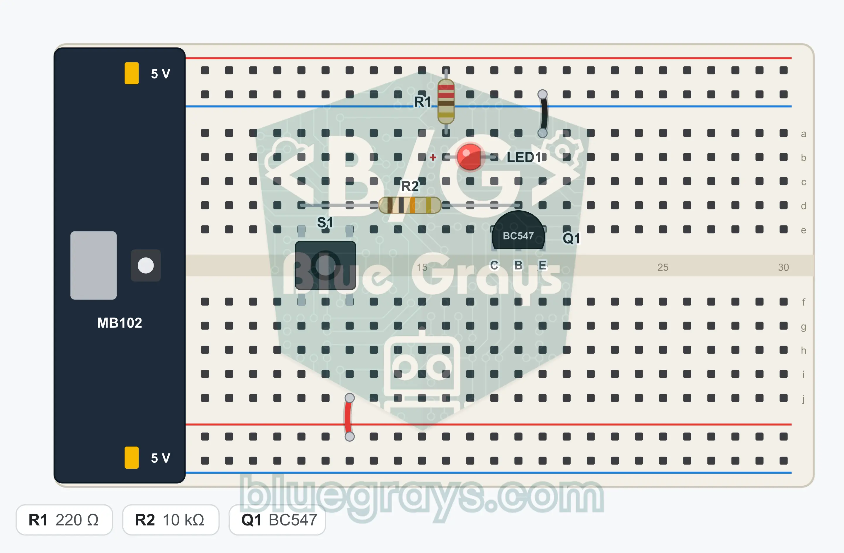
Plug Q1 (BC547) into the top half above the gap with its flat face toward you: its legs go into rows 18, 19 and 20. From left to right the legs are collector, base, emitter.
- 3
Connect the top half of row 20 to the top GND (−) rail with a jumper wire. This takes the emitter down to GND.
- 4
Plug one leg of R1 (220 Ω; red, red, brown) into the top + rail and the other leg into the top half of row 16.
- 5
Plug the long leg of LED1 into the top half of row 16, the same row as the leg of R1. Plug its short leg into row 18, that is, the collector row of Q1.
- 6
Place the S1 button over the center gap: its left legs go into row 10 and its right legs into row 12. Two legs stay in the top half, two legs in the bottom half.
- 7
Plug one leg of R2 (10 kΩ; brown, black, orange) into the top half of row 10 and the other leg into the top half of row 19, that is, the base row of Q1.
- 8
Connect the bottom half of row 12 to the bottom + rail with a jumper wire. The button gets 5 V from this corner.
- 9
Compare the connections with the schematic, then switch on the power module.
Tip: keep the battery or power supply disconnected while wiring.
Test Steps
- 1
Switch on the power module: the LED must stay off. With no base current the transistor is off.
- 2
Press and hold S1: the LED lights at full brightness.
- 3
Release S1: the LED goes out at once.
- 4
Press the button quickly several times in a row: the LED follows every press without delay. A transistor can switch on and off thousands of times a second.
How It Works
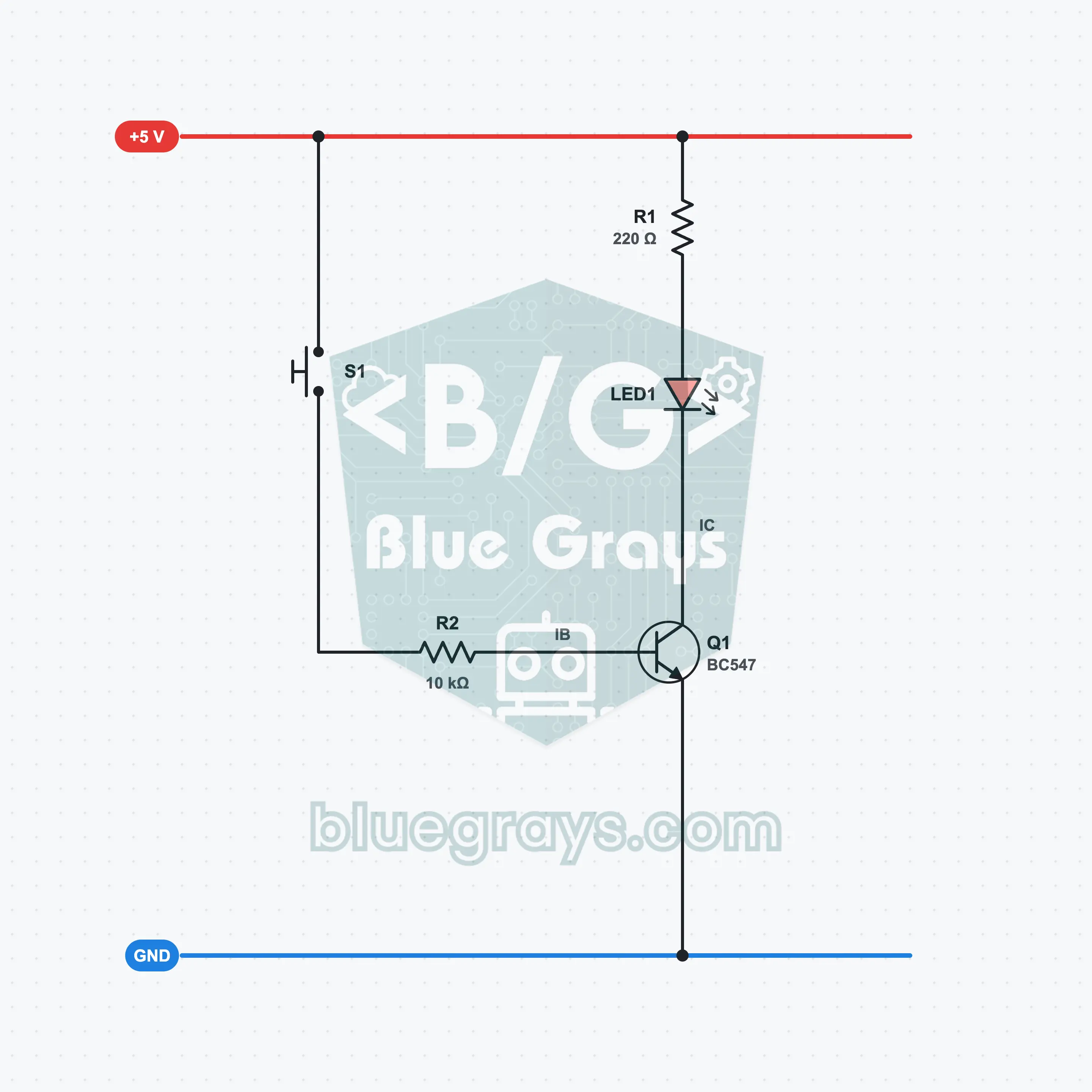
The button feeds a small current into the base of the BC547 through the 10 kΩ resistor; the transistor turns the LED's 13 mA current on and off.
The three legs of a transistor
The BC547 has three legs called base, collector and emitter. The base is the control input; the switch itself is between the collector and the emitter. When no current reaches the base, the path from collector to emitter is like an open switch and no current passes through the LED.
What happens when you press the button?
The button connects the base to 5 V through R2. About 0.7 V stays between base and emitter, the remaining 4.3 V drops across R2 and 0.43 mA flows into the base. This current turns the transistor on: the collector drops to 0.1 V and 13 mA flows from the + rail through R1, LED1 and the transistor to GND.
A small current controls a large one
The BC547 can amplify the base current at least 110 times. A base current of 0.43 mA is enough for up to 47 mA, while the LED needs only 13 mA. This is why the transistor turns on all the way. This is called saturation, and it is the state you want in switching circuits: the base current is chosen to be several times what is needed.
Why is the load on the collector?
The LED and its resistor are connected between the + rail and the collector, and the emitter goes straight to GND. This way the turn-on voltage of the base stays at 0.7 V whatever the load is, and the transistor turns fully on with ease. This layout is standard when you switch with an NPN transistor; you will see the same thing in relay and motor circuits.
Truth Table
| S1 | Base current | Q1 | LED1 |
|---|---|---|---|
| Not pressed | 0 mA | Off (cutoff) | 0 |
| Pressed | 0.43 mA | On (saturation) | 1 |
The current through the button is 0.43 mA and the current through the LED is 13 mA: the transistor switches about 30 times the current that drives it.
Formulas
Base current
IB = (Vcc − VBE) / R2
Example: (5 V − 0.7 V) / 10 kΩ = 0.43 mA
LED (collector) current
IC = (Vcc − VLED − VCE) / R1
Example: (5 V − 2 V − 0.1 V) / 220 Ω ≈ 13 mA
Smallest base current needed
IB(min) = IC / hFE
Example: 13 mA / 110 ≈ 0.12 mA; the 0.43 mA in the circuit is about 3.5 times this
Upper limit of the base resistor
R2(max) = (Vcc − VBE) × hFE / IC
Example: 4.3 V × 110 / 13 mA ≈ 36 kΩ; 10 kΩ is comfortably below this limit
Power dissipated in the transistor
P = VCE × IC
Example: 0.1 V × 13 mA ≈ 1.3 mW; the limit of the BC547 is 500 mW
Common Mistakes
The LED does not light at all.
The LED is reversed, or the flat face of the transistor is facing the back. The long leg of the LED must be in row 16, the short leg in row 18.
The LED lights without the button being pressed.
The short leg of the LED is plugged into GND or into the emitter row. The short leg goes into the collector row (18).
The LED is dim.
R2 has the wrong value. The colors of a 10 kΩ resistor are brown, black, orange.
The transistor heats up.
R2 has been left out and the base goes directly to the + rail. Switch off the power and fit R2 between the button and the base.
FAQ
Can't I just connect the button directly to the LED?
You can, and the LED still lights. But then all of the LED's current passes through the button. In this circuit only 0.43 mA passes through the button, and the transistor carries the 13 mA. With loads such as a relay or a motor this difference matters: thanks to the transistor, a weak signal turns a powerful load on and off.
What happens without the base resistor (R2)?
When you press the button, the base is connected directly to 5 V. The base-emitter junction behaves like a diode and starts conducting at about 0.7 V. With nothing left to limit the current, a very large current flows through the base and the transistor is destroyed. R2 holds this current at 0.43 mA.
Can I use another transistor instead of the BC547?
Most small NPN transistors will do: the BC548, BC337, 2N2222 or 2N3904. But pay attention to the leg order. On the 2N2222 and 2N3904, with the flat face toward you the order is emitter, base, collector, that is, the reverse of the BC547. PNP transistors such as the BC557 do not work with this wiring.
Does the transistor get hot?
No. A transistor that is fully on has about 0.1 V left between its collector and emitter. The power it dissipates is 0.1 V × 13 mA ≈ 1.3 mW, while the limit of the BC547 is 500 mW. If the transistor is heating up, a connection is wrong: switch off the power and check the base resistor and the leg order.