
Transistor Memory: Two-Button Flip-Flop Circuit
Two BC547 transistors latch each other and become a 1-bit memory: when you press S1 the red LED lights, when you press S2 the green LED lights, and it stays that way even after you release the button. No capacitor, no IC. This circuit is the bistable multivibrator, that is, the transistor version of the real flip-flop. You see how the smallest piece of computer memory works by building it with your own hands.
Video
Circuit Diagram
Breadboard Layout
Build Steps
- 1
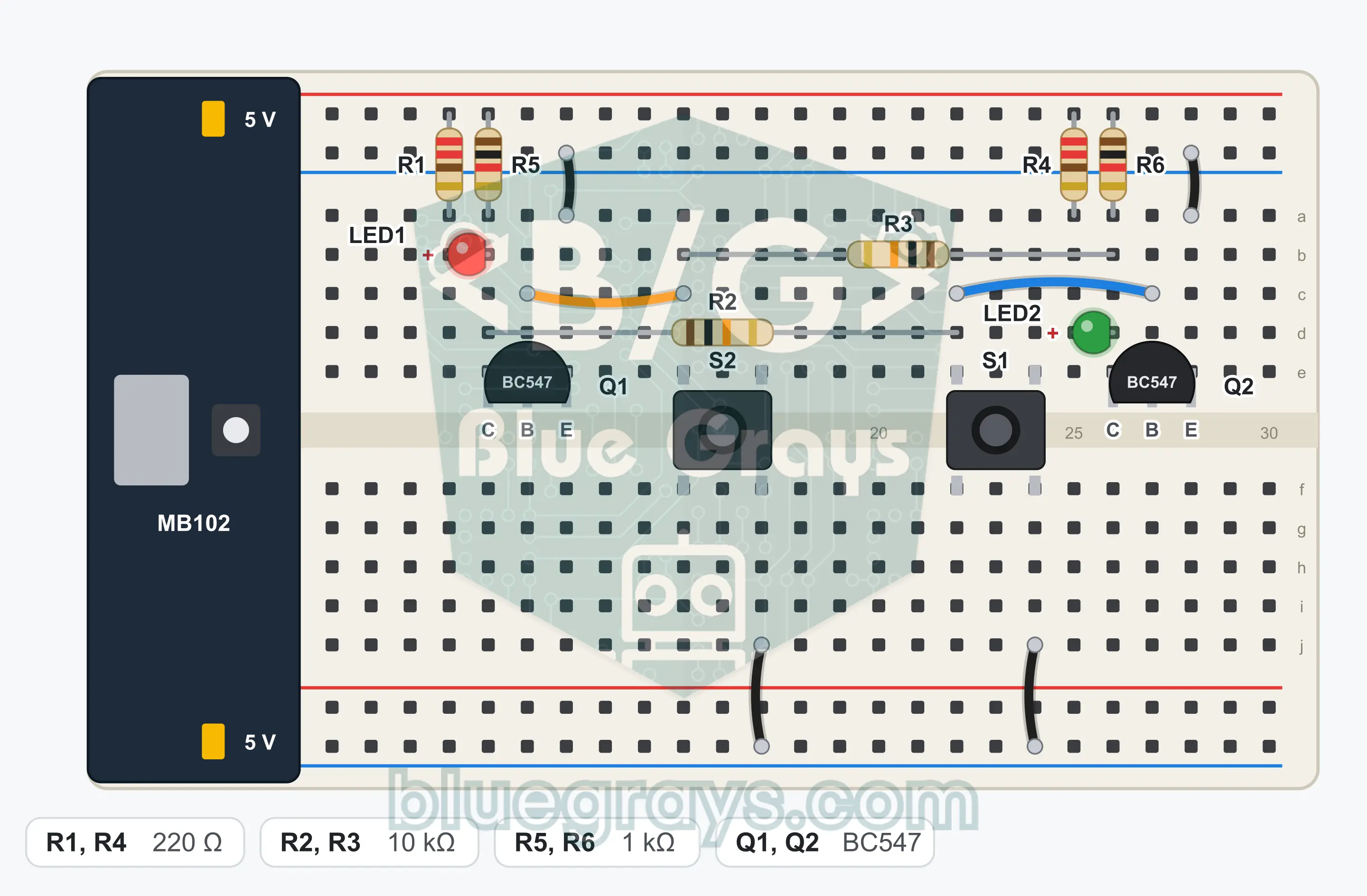
Plug the MB102 power module onto the end of the breadboard and set both jumper caps to the 5 V position. Leave the module's switch off for now.
- 2
Plug in Q1 (BC547) with its flat face toward you, so that its three legs land in three separate rows. From left to right the legs are collector, base, emitter.
- 3
Plug in Q2 (BC547) a few rows to the right of Q1, facing the same way.
- 4
Connect the emitter of Q1 to the GND (−) rail with a jumper wire.
- 5
Connect the emitter of Q2 to the GND rail with a jumper wire.
- 6
Fit R1 (220 Ω): one end into the + rail, the other end into an empty row.
- 7
Fit LED1 (red): long leg (anode) into the row of R1's free end, short leg (cathode) into the collector row of Q1.
- 8
Fit R5 (1 kΩ) between the + rail and the collector of Q1.
- 9
Fit R4 (220 Ω): one end into the + rail, the other end into an empty row.
- 10
Fit LED2 (green): long leg (anode) into the row of R4's free end, short leg (cathode) into the collector row of Q2.
- 11
Fit R6 (1 kΩ) between the + rail and the collector of Q2.
- 12
Fit R2 (10 kΩ) between the collector of Q1 and the base of Q2.
- 13
Fit R3 (10 kΩ) between the collector of Q2 and the base of Q1.
- 14
Place the S1 button over the center gap; connect the leg at one corner to the base of Q2 with a jumper wire and the leg at the diagonally opposite corner to the GND rail.
- 15
Place the S2 button over the center gap; connect the leg at one corner to the base of Q1 with a jumper wire and the leg at the diagonally opposite corner to the GND rail.
- 16
Compare the connections with the schematic, then switch on the power module.
Tip: keep the battery or power supply disconnected while wiring.
Test Steps
- 1
Switch on the power module: only one of the LEDs must light. Which one lights cannot be known in advance.
- 2
Press S1 briefly once and release it: the red LED must light, the green must go out, and it must stay that way.
- 3
Press S2 briefly once and release it: the green LED must light, the red must go out, and it must stay that way.
- 4
Press the same button several times in a row: the state must not change.
- 5
Press both buttons together: both LEDs go out. When you let go, the LED of the button you released last lights.
How It Works
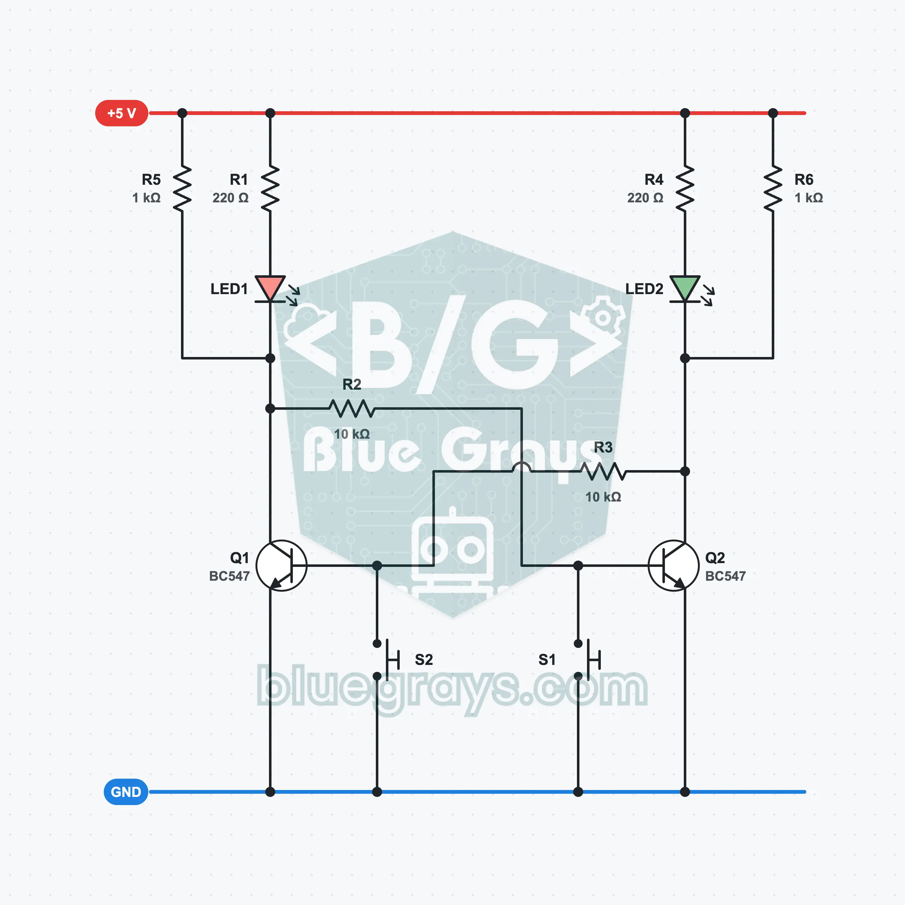
Two BC547s latch each other through cross-coupled resistors: S1 lights the red LED, S2 lights the green LED, and the state is kept after you release the button.
Two transistors that hold each other
The base of each transistor is connected to the collector of the other through a 10 kΩ resistor. If Q1 is conducting, its collector drops to 0.1 V; no current goes to the base of Q2 and Q2 stays off. Because Q2 is off, its collector is high and keeps feeding the base of Q1.
What happens when you press a button?
S1 connects the base of Q2 to GND. Q2 turns off, its collector rises to 4.6 V and 0.39 mA flows into the base of Q1 through R3. Q1 turns on and LED1 lights. Because the collector of Q1 has dropped, Q2 now stays off by itself too.
Why does it remember?
When you release the button, the only path that could pull the base of Q2 up is R2, and that is connected to the collector of Q1, which is at 0.1 V. So the circuit latches itself in this state. This is called positive feedback; because it has two stable states, the circuit is called bistable.
Why are the 1 kΩ resistors there?
A small current flows all the time from the collector of the off transistor to the opposite base. Without R5 and R6 this current would pass through the LED and the LED would glow faintly. The 1 kΩ resistors give the current a parallel path; only 0.39 V is left across the LED and it goes out completely.
Truth Table
| S1 | S2 | LED1 (red) | LED2 (green) |
|---|---|---|---|
| Not pressed | Not pressed | Previous state | Previous state |
| Pressed | Not pressed | 1 | 0 |
| Not pressed | Pressed | 0 | 1 |
| Pressed | Pressed | 0 | 0 |
The last row is the forbidden state: both LEDs go out, and when you release the buttons the result is set by the button released last.
Formulas
LED current
I = (Vcc − VLED − VCE) / R1
Example: (5 V − 2 V − 0.1 V) / 220 Ω ≈ 13 mA
Base current
IB = (Vcc − 0.7 V) / (R6 + R3)
Example: (5 V − 0.7 V) / (1 kΩ + 10 kΩ) = 0.39 mA
Collector voltage of the off transistor
VC = Vcc − R6 × IB
Example: 5 V − 1 kΩ × 0.39 mA = 4.61 V; only 0.39 V is left across the unlit LED
Collector current of the conducting transistor
IC = ILED + (Vcc − VCE) / R5
Example: 13 mA + (5 V − 0.1 V) / 1 kΩ ≈ 18 mA; a base current of 0.39 mA is enough for up to 43 mA with a gain of at least 110
Common Mistakes
The LED goes back to its previous state when you release the button.
One of the cross-coupled resistors is in the wrong place. R2 goes from the collector of Q1 to the base of Q2, R3 from the collector of Q2 to the base of Q1.
Both LEDs light at once.
R2 or R3 is connected to the + rail instead of a collector. One end of each resistor must be in the collector row of the opposite transistor.
The unlit LED glows faintly.
R5 or R6 is missing. The 1 kΩ resistors are fitted between the + rail and the collector.
One LED does not light at all.
The LED or the transistor on that side is reversed. With the flat face of the BC547 toward you, the order is collector, base, emitter.
FAQ
Is this circuit really a memory?
Yes, a 1-bit memory. It remembers which button you pressed last for as long as the power stays on. Static memory cells in computers work on the same idea: two inverters that hold each other. When you cut the power the information is erased, and when you switch it on the circuit starts in a random state.
What happens without the 1 kΩ resistors R5 and R6?
The circuit still works, but the LED that should be off glows faintly. The 0.39 mA current that goes from the collector of the off transistor to the opposite base has to pass through the LED. The 1 kΩ resistors carry this current past the LED, and the LED goes out completely.
Which LED lights when I switch on the power?
It cannot be predicted. The two transistors race at power-on; the side whose gain is a little higher or whose connection is a little shorter gets ahead. Most of the time the same LED lights every time, but this is not guaranteed. To fix the power-on state you can add the capacitor from the task section.
What happens if I press both buttons at the same time?
The bases of both transistors go down to GND, both turn off and both LEDs go out together. This is what is called the forbidden state in flip-flops. When you release the buttons, the LED of the one you released later lights; if you release them at exactly the same moment, the result is random.