
EL-87BeginnerPremiumTransistor circuits
Remote Control Tester: See the Invisible Light
Press a button on a TV remote: the LED flickers and the buzzer crackles. The light at the tip of the remote is infrared, so your eyes cannot see it; the VS1838B receiver can, and it pulls its output low. A PNP transistor called the BC557 uses this low signal to drive an LED and an active buzzer. In a few seconds you find out which remote works and which one has a dead battery. It is also a good circuit for meeting the PNP transistor: it conducts while its base is low.
0.0(0)
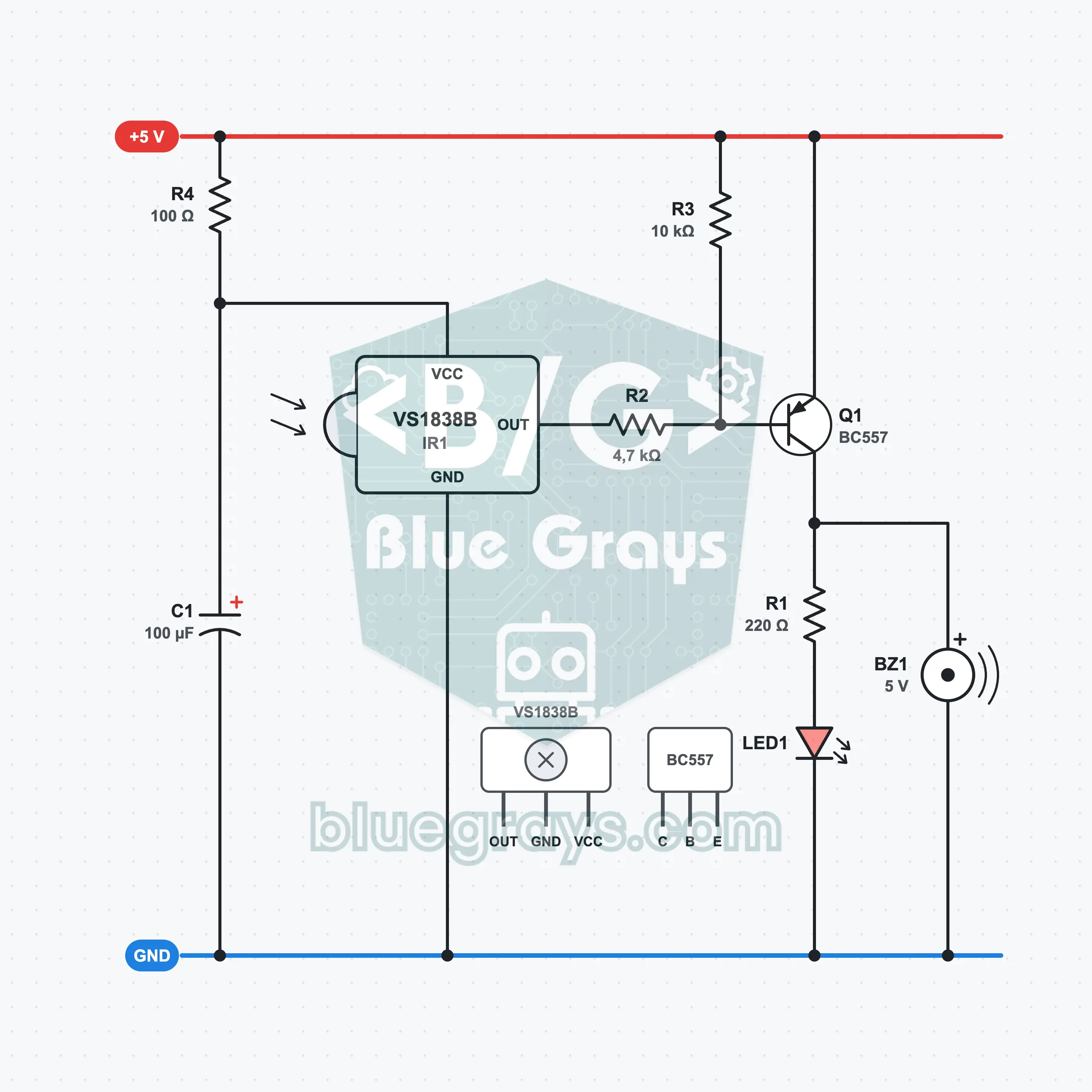
It is built with a 5 V supply, one VS1838B infrared receiver, one BC557, four resistors, a 100 µF capacitor, one LED and one active buzzer. The receiver's output is at 5 V while idle and drops to about 0.2 V when a 38 kHz remote signal arrives. The PNP transistor, whose emitter is on the + rail, turns on when its base is pulled down through 4.7 kΩ; the LED lights with about 13 mA and the buzzer sounds. The 100 Ω resistor and the 100 µF capacitor filter the receiver's supply. What you learn: infrared light, the 38 kHz carrier, an active-low output, switching with a PNP transistor and the pull-up resistor.
Premium Content
This circuit's build steps, how-it-works guide and FAQ are open to Premium members.
- Build Steps
- How It Works
- Frequently Asked Questions