
TCS34725 Arduino: I2C RGB Color Sensor, Lux and Color Temp
TCS34725 Arduino wiring, integration time and gain, color temperature and lux, TCS3200 comparison, a color sorting machine, plus ESP32 and Pico code.

The TCS34725 is a digital RGB color sensor that talks over I2C and is one of the most accurate and easiest ways to detect color with Arduino. It gives you the amount of red, green, blue and total (clear) light from an object you hold in front of it, or from the ambient light, as 16-bit numbers. Because the chip also has an infrared blocking filter, its readings are much less affected by the invisible light coming from daylight and bulbs. Wiring the TCS34725 to Arduino takes just two data wires (SDA and SCL), and with the Adafruit library you read your first values in a few lines.
In this post you'll learn what's inside the sensor, how the integration time and gain settings change the measurement, and how to calculate color temperature (Kelvin) and lux from the raw numbers, step by step. Then you'll compare it with the older but common TCS3200, build a calibrated color sorting machine, and use the same sensor with the ESP32 and the Raspberry Pi Pico (MicroPython).
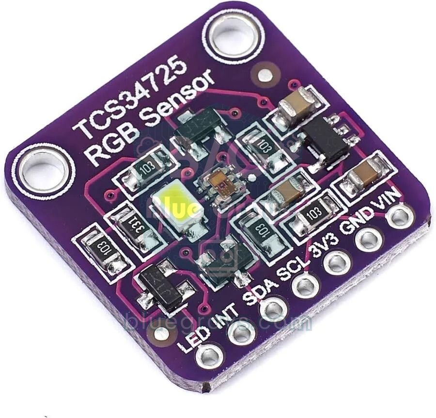
What is the TCS34725 and how does it work?
The chip has 12 small photodiodes in a 3×4 layout. Three of them are covered by a red filter, three by a green filter and three by a blue filter; the remaining three have no filter and see the total light (clear, C). The current produced by each group is collected over a set time in a separate 16-bit analog-to-digital converter. This time is called the integration time. When it ends, the four results (R, G, B, C) are written to registers and you read them over I2C. The infrared blocking filter over the photodiodes largely cuts light above 700 nm, which our eyes can't see. That way the TCS34725 measures colors closer to how the human eye perceives them. Most modules also have a neutral white LED next to the chip. When you read an object's color, you're actually measuring the part of this LED's light that bounces off the object and comes back.
| Feature | Value |
|---|---|
| Measured channels | Red (R), green (G), blue (B), unfiltered (C) |
| Photodiode array | 3×4, 12 photodiodes in total |
| Resolution | 16 bits per channel (0–65535) |
| Interface | I2C, up to 400 kHz |
| I2C address | 0x29 (fixed) |
| Supply | Chip 2.7–3.6 V; module with regulator 3.3–5 V |
| Current | About 235 µA while measuring, 2.5 µA in sleep (LED excluded) |
| IR filter | On the chip, infrared blocking |
| Dynamic range | 3,800,000:1 |
| Integration time | 2.4 ms – 614 ms (in 2.4 ms steps) |
| Gain | 1x, 4x, 16x, 60x |
| On-board LED | Neutral white, about 4150 K |
Integration time and gain settings
Integration time is similar to exposure time on a camera. The longer it is, the more light the sensor collects, the numbers get bigger, and noise in dark environments drops. On the other hand, every reading takes longer and the channels saturate more easily in bright light. The time is set in 2.4 ms steps with the ATIME register. The largest number a channel can reach is given by the formula (256 − ATIME) × 1024, and the result can't exceed 65535. The table below shows the most common values and when to choose them.
| ATIME | Cycles | Time | Max count | When? |
|---|---|---|---|---|
| 0xFF | 1 | 2.4 ms | 1024 | Very bright light, very fast reading |
| 0xF6 | 10 | 24 ms | 10240 | In sunlight, fast-moving objects |
| 0xEB | 21 | 50 ms | 21504 | A good starting point for LED color reading |
| 0xD6 | 42 | 101 ms | 43008 | Measuring ambient light indoors |
| 0xC0 | 64 | 154 ms | 65535 | Dim environments, full 16-bit resolution |
| 0x00 | 256 | 614 ms | 65535 | Very dark environments, slow reading |
Gain amplifies the collected signal in the analog domain. The options are 1x, 4x, 16x and 60x. Raising the gain increases sensitivity without lengthening the time, but it increases noise too. The practical rule: always light the object with the LED from the same distance and start with 50 ms and 4x. If C stays far below the maximum count (for example below 1000), raise the gain to 16x. If C approaches saturation, lower the gain or shorten the time. Once a channel hits the ceiling, that reading is no longer correct, because the number can't grow any further as light increases and the color ratios get distorted. The datasheet also notes that for times shorter than 150 ms, saturation can begin at about 75% of the maximum count because of ripple. So at 50 ms, treat about 16000 as the safe upper limit.
TCS34725 wiring (Arduino Uno, ESP32, Pico)
| TCS34725 pin | Arduino Uno | ESP32 | Raspberry Pi Pico |
|---|---|---|---|
| VIN | 5V | 3V3 | 3V3(OUT) (pin 36) |
| GND | GND | GND | GND |
| SDA | A4 | GPIO 21 | GP4 (pin 6) |
| SCL | A5 | GPIO 22 | GP5 (pin 7) |
| LED | Floating: LED on / GND: LED off | Floating or GND | Floating or GND |
| INT | Floating (optional interrupt output) | Floating | Floating |
| 3V3 | Don't connect (regulator output) | Don't connect | Don't connect |
Step by step: your first color reading with Arduino Uno
- Wire the module as in the table: VIN to 5V, GND to GND, SDA to A4, SCL to A5. Leave the LED and INT pins unconnected for now.
- In the Arduino IDE, open the Library Manager, search for the Adafruit TCS34725 library and install it; if it asks about dependencies, install Adafruit BusIO too. If you get stuck, take a look at adding Arduino libraries.
- Upload the code below and open the Serial Monitor at 9600 baud.
- Hold red, green and blue papers 1–2 cm in front of the sensor and watch which channel grows for each color.
- Move the paper closer and farther to see how the numbers change, and make sure the C value doesn't reach the saturation limit.
1#include <Wire.h>
2#include <Adafruit_TCS34725.h>
3
4// 50 ms entegrasyon, 4x kazanç / 50 ms integration, 4x gain
5Adafruit_TCS34725 tcs(TCS34725_INTEGRATIONTIME_50MS, TCS34725_GAIN_4X);
6
7const float ATIME_MS = 50.4;     // 21 döngü x 2,4 ms / 21 cycles x 2.4 ms
8const float GAIN = 4.0;          // kazanç katsayısı / gain factor
9const uint16_t DOYMA = 16128;    // 21504'ün %75'i / 75% of 21504 (ripple saturation)
10
11void setup() {
12  Serial.begin(9600);
13  if (tcs.begin()) {
14    Serial.println(F("TCS34725 bulundu / found"));
15  } else {
16    Serial.println(F("Sensor yok, kablolari kontrol et / No sensor, check wiring"));
17    while (1);
18  }
19}
20
21// ams DN40 formülü ile lüks / lux with the ams DN40 formula
22float luxHesapla(uint16_t r, uint16_t g, uint16_t b, uint16_t c) {
23  float ir = ((float)r + g + b - c) / 2.0;   // kızılötesi tahmini / IR estimate
24  if (ir < 0) ir = 0;
25  float r2 = r - ir;
26  float g2 = g - ir;
27  float b2 = b - ir;
28  float cpl = (ATIME_MS * GAIN) / 310.0;     // lüks başına sayım / counts per lux
29  float lux = (0.136 * r2 + 1.0 * g2 - 0.444 * b2) / cpl;
30  return lux < 0 ? 0 : lux;
31}
32
33void loop() {
34  uint16_t r, g, b, c;
35  tcs.getRawData(&r, &g, &b, &c);            // bir entegrasyon süresi bekler / waits one integration time
36  uint16_t cct = tcs.calculateColorTemperature_dn40(r, g, b, c);
37  float lux = luxHesapla(r, g, b, c);
38
39  Serial.print(F("R:")); Serial.print(r);
40  Serial.print(F(" G:")); Serial.print(g);
41  Serial.print(F(" B:")); Serial.print(b);
42  Serial.print(F(" C:")); Serial.print(c);
43  Serial.print(F(" CCT:")); Serial.print(cct); Serial.print(F(" K"));
44  Serial.print(F(" Lux:")); Serial.print(lux, 0);
45  if (c > DOYMA) Serial.print(F("  DOYMA! / SATURATED!"));
46  Serial.println();
47  delay(500);
48}
The integration time and gain are given together when the object is created; if you like, you can change them later with tcs.setIntegrationTime() and tcs.setGain(). getRawData() waits one integration time and then reads the four channels. So if you choose 614 ms, you can't even do two readings per second. For color temperature we used the library's calculateColorTemperature_dn40() function; it returns an invalid value (65535) when saturated. We did the lux calculation ourselves, because the library's calculateLux() function doesn't take the time and gain into account, so its result drifts when you change the settings. Always keep the ATIME_MS and GAIN constants in the code the same as the settings you chose.
Color temperature and lux calculation
Lux (lx) shows how bright the light falling on a surface is to the human eye. A dim room is about 50–100 lx and a well-lit office about 300–500 lx; outdoors under an overcast sky you measure a few thousand lx, while midday sun reaches up to 100,000 lx. Color temperature (CCT) describes the tone of white light in Kelvin. A candle flame is about 1900 K, an incandescent bulb 2700 K, a warm white LED 3000 K, midday sun 5500 K and an overcast sky around 6500–7500 K. As the value gets smaller the light shifts toward yellow-orange, and as it gets bigger toward blue. ams, the maker of the TCS34725, recommends these steps in its DN40 application note to calculate these two quantities from the raw numbers:
| Step | Formula |
|---|---|
| 1. Infrared component | IR = (R + G + B − C) / 2 (0 if negative) |
| 2. IR-free channels | R' = R − IR, G' = G − IR, B' = B − IR |
| 3. Counts per lux | CPL = (ATIME_ms × Gain) / (GA × 310) |
| 4. Lux | Lux = (0.136 × R' + 1.000 × G' − 0.444 × B') / CPL |
| 5. Color temperature | CCT = 3810 × (B' / R') + 1391 |
Let's look at an example: say you read R = 1200, G = 1000, B = 800, C = 2800 with 50.4 ms and 4x gain. IR = (1200 + 1000 + 800 − 2800) / 2 = 100; the IR-free values are R' = 1100, G' = 900, B' = 700. CPL = 50.4 × 4 / 310 ≈ 0.650. Lux = (0.136 × 1100 + 900 − 0.444 × 700) / 0.650 = 738.8 / 0.650 ≈ 1136 lx. The color temperature is 3810 × 700 / 1100 + 1391 ≈ 3816 K. GA in the formula shows how much the glass or plastic cover in front of the sensor attenuates the light; for a bare sensor use 1. If you place the sensor behind a cover, you should raise GA above 1 and calibrate it by comparing with a known lux meter.
TCS34725 vs TCS3200
| Feature | TCS34725 | TCS3200 |
|---|---|---|
| Output | I2C, 16-bit digital number | Square wave, frequency proportional to light |
| Pins used | 2 (SDA, SCL) | 5–6 (S0–S3, OUT, OE) |
| Photodiodes | 3×4 = 12 | 8×8 = 64 |
| IR filter | Yes, on the chip | No, sensitive to infrared |
| Settings | Time 2.4–614 ms, gain 1x–60x | Frequency scaling 2%, 20%, 100% |
| Supply | Module 3.3–5 V (chip 2.7–3.6 V) | 2.7–5.5 V |
| On-board LED | 1 neutral white | 4 white |
| Reading method | Four channels at once, from registers | Select filter by filter and measure frequency with pulseIn |
| Lux and color temperature | Calculated directly with formulas | Hard, needs detailed calibration |
The TCS3200 is still very common in school projects because its four LEDs light the object strongly and it runs comfortably on 5 V. But switching the filter for each color with the S2 and S3 pins and measuring frequency costs both pins and time. Because it has no IR filter, its readings are also affected more by ambient light. The TCS34725, on the other hand, connects with two wires, reads four channels at once, and thanks to the adjustable time and gain works from darkness to full sunlight. If you're starting a new project, choose the TCS34725; if you already have a TCS3200, the TCS3200 color sensor post will guide you. If you also want to detect gestures and proximity in addition to color, the APDS-9960 is a good alternative too.
Color sorting machine example
A classic school and science fair project: stop colored candies or beads sliding down a ramp in front of the sensor and direct them into different bins by color. Here the sensor measures the color, and a servo motor turns the chute to the angle of the matching bin. The most important trick is to use ratios, not raw numbers. When the object moves a bit farther away, R, G and B all drop together, but the R/(R+G+B) ratio stays almost the same. For calibration, place one object of each color in front of the sensor, note the nr, ng and nb values printed in the Serial Monitor, and write them into the ref table in the code; the values in the code are only examples. If you place the sensor inside a black tube and always hold the object at the same distance (ideally 5–10 mm), the effect of ambient light disappears and accuracy improves considerably.
1#include <Wire.h>
2#include <Adafruit_TCS34725.h>
3#include <Servo.h>
4
5Adafruit_TCS34725 tcs(TCS34725_INTEGRATIONTIME_50MS, TCS34725_GAIN_4X);
6Servo oluk;                                        // yönlendirme oluğu / sorting chute
7
8const int RENK_SAYISI = 4;
9const char* renkAd[RENK_SAYISI] = {"KIRMIZI", "YESIL", "MAVI", "SARI"};
10// Kalibrasyonla bul: her renk için nr, ng, nb / find by calibration: nr, ng, nb per color
11const float ref[RENK_SAYISI][3] = {
12  {0.52, 0.26, 0.22},
13  {0.27, 0.44, 0.29},
14  {0.20, 0.31, 0.49},
15  {0.42, 0.39, 0.19}
16};
17const int aci[RENK_SAYISI] = {20, 65, 110, 155};   // her kutunun servo açısı / servo angle of each bin
18const uint16_t BOS_ESIK = 300;                     // tüp boşken C bunun altında / C stays below this when empty
19
20void setup() {
21  Serial.begin(9600);
22  if (!tcs.begin()) {
23    Serial.println(F("TCS34725 bulunamadi / not found"));
24    while (1);
25  }
26  oluk.attach(9);                                  // servo sinyali D9 / servo signal on D9
27  oluk.write(90);                                  // bekleme konumu / idle position
28}
29
30int renkBul(float nr, float ng, float nb) {
31  int enIyi = -1;
32  float enKucuk = 1000.0;
33  for (int i = 0; i < RENK_SAYISI; i++) {
34    float d = sq(nr - ref[i][0]) + sq(ng - ref[i][1]) + sq(nb - ref[i][2]);
35    if (d < enKucuk) {
36      enKucuk = d;
37      enIyi = i;
38    }
39  }
40  if (enKucuk > 0.004) return -1;                  // hiçbir renge yakın değil / not close to any color
41  return enIyi;
42}
43
44void loop() {
45  uint16_t r, g, b, c;
46  tcs.getRawData(&r, &g, &b, &c);
47  if (c < BOS_ESIK) {                              // önünde nesne yok / no object in front
48    delay(50);
49    return;
50  }
51  float top = (float)r + g + b;
52  float nr = r / top;
53  float ng = g / top;
54  float nb = b / top;
55  Serial.print(F("nr=")); Serial.print(nr, 3);
56  Serial.print(F(" ng=")); Serial.print(ng, 3);
57  Serial.print(F(" nb=")); Serial.print(nb, 3);
58
59  int renk = renkBul(nr, ng, nb);
60  if (renk >= 0) {
61    Serial.print(F(" -> "));
62    Serial.println(renkAd[renk]);
63    oluk.write(aci[renk]);                         // oluğu kutuya çevir / turn chute to the bin
64    delay(800);                                    // nesnenin kaymasını bekle / wait for the object to slide
65    oluk.write(90);
66  } else {
67    Serial.println(F(" -> bilinmiyor / unknown"));
68  }
69  delay(300);
70}
On every reading the code first looks at the C value. When the tube is empty, the LED's light isn't reflected back, so C stays small and the machine waits; if ambient light enters the tube, adjust BOS_ESIK for your own setup. When an object arrives, the color ratios are found by dividing R, G and B by their sum. Then the squared distance to each reference color is calculated and the nearest color is chosen. The distance threshold of 0.004 classifies objects that look like no color as unknown; if you lower the threshold, the machine becomes more selective. To add a new color, it's enough to add a row to the ref, renkAd and aci arrays and update RENK_SAYISI. Powering the servo from a separate 5 V supply prevents I2C readings from being corrupted while the motor moves. Averaging a few measurements also makes the readings more stable; see the sensor data filtering post for that.
TCS34725 with ESP32: mirroring the color on an RGB LED
On the ESP32 the same Adafruit library works without changes. The I2C pins are GPIO 21 (SDA) and GPIO 22 (SCL) by default, and powering the module from the 3V3 pin is the safest. The example below imitates the color the sensor sees with a common-cathode RGB LED and prints the color code in #RRGGBB format to the Serial Monitor. The getRGB() function divides the colors by the C channel to bring them into the 0–255 range; the code scales the strongest channel to 255 and applies gamma correction to bring faint colors to life. Because the PWM functions differ between versions 2.x and 3.x of the ESP32 Arduino core, the code is split for the two versions. You can find the right resistor for each LED leg with the LED resistor calculator.
1#include <Wire.h>
2#include <Adafruit_TCS34725.h>
3
4Adafruit_TCS34725 tcs(TCS34725_INTEGRATIONTIME_50MS, TCS34725_GAIN_4X);
5
6const int PIN_R = 25;   // RGB LED kırmızı / red
7const int PIN_G = 26;   // RGB LED yeşil / green
8const int PIN_B = 27;   // RGB LED mavi / blue
9
10void pwmBaslat() {
11#if ESP_ARDUINO_VERSION_MAJOR >= 3
12  ledcAttach(PIN_R, 5000, 8);    // core 3.x: pin, frekans, çözünürlük / pin, frequency, resolution
13  ledcAttach(PIN_G, 5000, 8);
14  ledcAttach(PIN_B, 5000, 8);
15#else
16  ledcSetup(0, 5000, 8);         // core 2.x: kanal, frekans, çözünürlük / channel, frequency, resolution
17  ledcSetup(1, 5000, 8);
18  ledcSetup(2, 5000, 8);
19  ledcAttachPin(PIN_R, 0);
20  ledcAttachPin(PIN_G, 1);
21  ledcAttachPin(PIN_B, 2);
22#endif
23}
24
25void ledYaz(uint8_t r, uint8_t g, uint8_t b) {
26#if ESP_ARDUINO_VERSION_MAJOR >= 3
27  ledcWrite(PIN_R, r);
28  ledcWrite(PIN_G, g);
29  ledcWrite(PIN_B, b);
30#else
31  ledcWrite(0, r);
32  ledcWrite(1, g);
33  ledcWrite(2, b);
34#endif
35}
36
37uint8_t duzelt(float v, float enBuyuk) {
38  float x = v / enBuyuk;         // en güçlü kanal 1 olur / strongest channel becomes 1
39  x = powf(x, 2.5f);             // gama: renkleri canlandır / gamma: make colors vivid
40  return (uint8_t)(x * 255.0f);
41}
42
43void setup() {
44  Serial.begin(115200);
45  Wire.begin(21, 22);            // SDA, SCL
46  if (!tcs.begin(TCS34725_ADDRESS, &Wire)) {
47    Serial.println("TCS34725 bulunamadi / not found");
48    while (true) delay(10);
49  }
50  pwmBaslat();
51}
52
53void loop() {
54  float r, g, b;
55  tcs.getRGB(&r, &g, &b);        // C kanalına göre 0-255 / normalized to clear, 0-255
56  float enBuyuk = fmaxf(r, fmaxf(g, b));
57  if (enBuyuk < 1.0f) enBuyuk = 1.0f;
58  uint8_t R = duzelt(r, enBuyuk);
59  uint8_t G = duzelt(g, enBuyuk);
60  uint8_t B = duzelt(b, enBuyuk);
61  ledYaz(R, G, B);
62  Serial.printf("#%02X%02X%02X\n", R, G, B);
63  delay(100);
64}
Raspberry Pi Pico with TCS34725 (MicroPython)
In MicroPython you don't have to install a ready-made library; the TCS34725's register structure is simple, so you can talk to it directly in a few lines. The command bit (0x80) is added to each register address, and for multi-byte reads the auto-increment bit (0x20) is used too. The code first reads the ID register (0x12): it should return 0x44 for the TCS34725 and 0x4D for the TCS34727. Then it sets ATIME to 0xEB (about 50 ms) and the gain to 4x, turns the sensor on, and calculates lux and color temperature with the DN40 formula on every measurement. If you're new to the Pico and MicroPython, you can first take a look at What is the Raspberry Pi Pico.
1from machine import Pin, I2C
2import time
3
4ADDR = 0x29          # sabit I2C adresi / fixed I2C address
5CMD = 0x80           # komut biti / command bit
6AUTO = 0x20          # otomatik artırma / auto-increment
7ATIME_MS = 50.4      # 0xEB = 21 döngü x 2,4 ms / 21 cycles x 2.4 ms
8GAIN = 4
9
10i2c = I2C(0, sda=Pin(4), scl=Pin(5), freq=400000)
11
12def yaz(reg, deger):
13    i2c.writeto_mem(ADDR, CMD | reg, bytes([deger]))
14
15def oku(reg):
16    return i2c.readfrom_mem(ADDR, CMD | reg, 1)[0]
17
18print("ID:", hex(oku(0x12)))   # 0x44 = TCS34725, 0x4D = TCS34727
19
20yaz(0x01, 0xEB)      # ATIME: yaklaşık 50 ms / about 50 ms
21yaz(0x0F, 0x01)      # kazanç 4x (0=1x, 1=4x, 2=16x, 3=60x) / gain 4x
22yaz(0x00, 0x01)      # PON: güç aç / power on
23time.sleep_ms(3)
24yaz(0x00, 0x03)      # PON + AEN: ölçümü başlat / start measuring
25
26def rgbc_oku():
27    while not (oku(0x13) & 0x01):    # AVALID: veri hazır mı? / data ready?
28        time.sleep_ms(5)
29    d = i2c.readfrom_mem(ADDR, CMD | AUTO | 0x14, 8)
30    c = d[0] | (d[1] << 8)
31    r = d[2] | (d[3] << 8)
32    g = d[4] | (d[5] << 8)
33    b = d[6] | (d[7] << 8)
34    return r, g, b, c
35
36def lux_cct(r, g, b, c):
37    ir = max(0, (r + g + b - c) / 2)         # kızılötesi tahmini / IR estimate
38    r2, g2, b2 = r - ir, g - ir, b - ir
39    cpl = (ATIME_MS * GAIN) / 310            # lüks başına sayım / counts per lux
40    lux = max(0, (0.136 * r2 + g2 - 0.444 * b2) / cpl)
41    cct = 3810 * b2 / r2 + 1391 if r2 > 0 else 0
42    return lux, cct
43
44while True:
45    r, g, b, c = rgbc_oku()
46    lux, cct = lux_cct(r, g, b, c)
47    print("R:", r, "G:", g, "B:", b, "C:", c, "Lux: %.0f" % lux, "CCT: %.0f K" % cct)
48    time.sleep(0.5)
TCS34725 project ideas
- Color sorting machine: Sort candies or beads into bins by color using a servo and a ramp (the example above).
- Color-copying lamp: Read the color of a fabric or paper and mirror it exactly on a WS2812B NeoPixel strip.
- Light meter: Measure the lux and color temperature of a room and show them on a display; check whether your desk reaches the 500 lx target.
- Color-rule robot: Add a TCS34725 to a line-following robot and set rules like stop at a red mark and turn at green.
- Device that speaks the color: Build an assistive tool for the visually impaired that says the detected color out loud with a DFPlayer Mini.
- Fruit ripeness indicator: Track a tomato or banana turning from green to red or yellow using color ratios.
Common mistakes and how to fix them
| Symptom | Likely cause | Fix |
|---|---|---|
| It prints "TCS34725 not found" | SDA and SCL swapped, no power, or a loose wire | Check that SDA=A4 and SCL=A5 on the Uno; look for address 0x29 with an I2C scanner |
| All channels are very large and don't change | Saturation: too much light for the chosen time and gain | Lower the gain to 1x, shorten the time, or move the object a bit farther away |
| Numbers are very small and colors jump around | Not enough light | Turn on the LED, set the gain to 16x or 60x, lengthen the time |
| The same object shows a different color at a different distance | Comparison was made with raw values | Use the R/(R+G+B) ratios and fix the distance |
| Results change when a window is opened | Ambient light is mixing into the measurement | Surround the sensor with a black tube or a shroud |
| Color temperature is always around 4000 K | The on-board LED was left on | Connect the LED pin to GND or turn it off with a digital pin |
| Readings are very slow | Long integration time (e.g. 614 ms) | getRawData() waits for that time; choose 24–50 ms |
| Red and orange get mixed up | Reference ratios are too close to each other | Calibrate in the final setup, lower the threshold, average a few readings |
The TCS34725 is a versatile sensor that connects with two wires and, thanks to its adjustable sensitivity and IR filter, reliably measures both object color and ambient light. The secret to correct results is three things: choosing a time and gain that prevent saturation, working with ratios instead of raw numbers, and calibrating in the final setup. If you'd like to start measuring light with a simpler sensor, the LDR light sensor is a good first step. In the BlueGrays app you'll find step-by-step projects with circuit diagrams and code for light measurement with an LDR, RGB LED color fading, an ESP32 color mixer lamp and servos, and you can build your own color-sensing machine on top of them.
Frequently asked questions
What is the difference between the TCS34725 and the TCS3200?
The TCS34725 gives four channels at once as 16-bit numbers over I2C and has an infrared blocking filter on the chip. The TCS3200 selects the color filter one by one with the S2–S3 pins and produces a frequency output; it needs 5–6 pins and, with no IR filter, is affected more by ambient light. For accuracy and easy wiring, the TCS34725 is the better choice.
What is the TCS34725's I2C address, and can it be changed?
The TCS34725's address is fixed at 0x29 and can't be changed. If you want to connect two sensors to the same board, you can use an I2C multiplexer such as the TCA9548A. On the ESP32 and Pico, you can also connect each sensor to a separate I2C bus.
Does the TCS34725 work at 5 V?
The chip itself runs on 2.7–3.6 V. However, since most modules have a 3.3 V regulator, you can feed 5 V to the VIN pin and connect the module straight to an Arduino Uno. Applying 5 V to the 3V3 pin damages the chip; if your board has no regulator, power the module with 3.3 V.
Why is my TCS34725 reading colors wrong?
The most common causes are saturation, insufficient light, ambient light mixing in, and comparing with raw numbers. Light the object with the LED from a fixed distance, make sure the C value stays below the saturation limit, and work with ratios like R/(R+G+B). Also calibrate the reference colors in your final setup.
How do I turn off the LED on the TCS34725?
When you connect the module's LED pin to GND, the white LED turns off. If you connect the pin to a digital output, you can turn it off by writing LOW and on by writing HIGH. The LED must be off when you measure ambient light or color temperature.
How accurate is lux measurement with the TCS34725?
The TCS34725 isn't as precise as a professional lux meter, but with the DN40 formula and the right time and gain settings it gives quite useful approximate values indoors. If the sensor is behind a glass or plastic cover, you need to calibrate it with the GA factor. If you only need brightness, the BH1750, which gives lux directly, is a simpler option.
Projects to build after reading this
See all projects
Measuring Light Intensity with an LDR
Want to see how bright your room is as a number? The LDR, a small part that reacts to light, measures the light around it, and the Arduino writes the value to your computer screen every half second.

Reading Light Intensity with the ESP32 LDR Module
Real-time monitoring of the LDR module's raw ADC value and relative light percentage calculated from dark and light reference values in the Serial Monitor. This percentage is not a lux measurement. Teaches the module’s calibration logic. It is ideal to complete this before Project 10, as it is used to determine the threshold value.
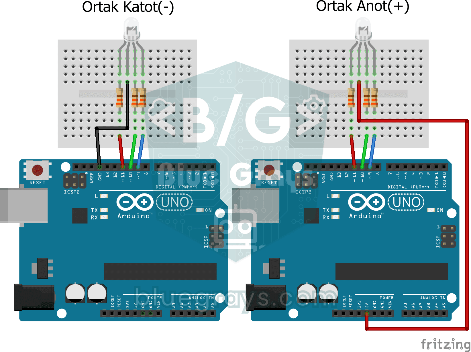
Using an RGB LED
Three colours hide inside a single LED: the RGB LED lights up red, then green, then blue, each colour on for half a second and off for half a second, before the cycle starts again.
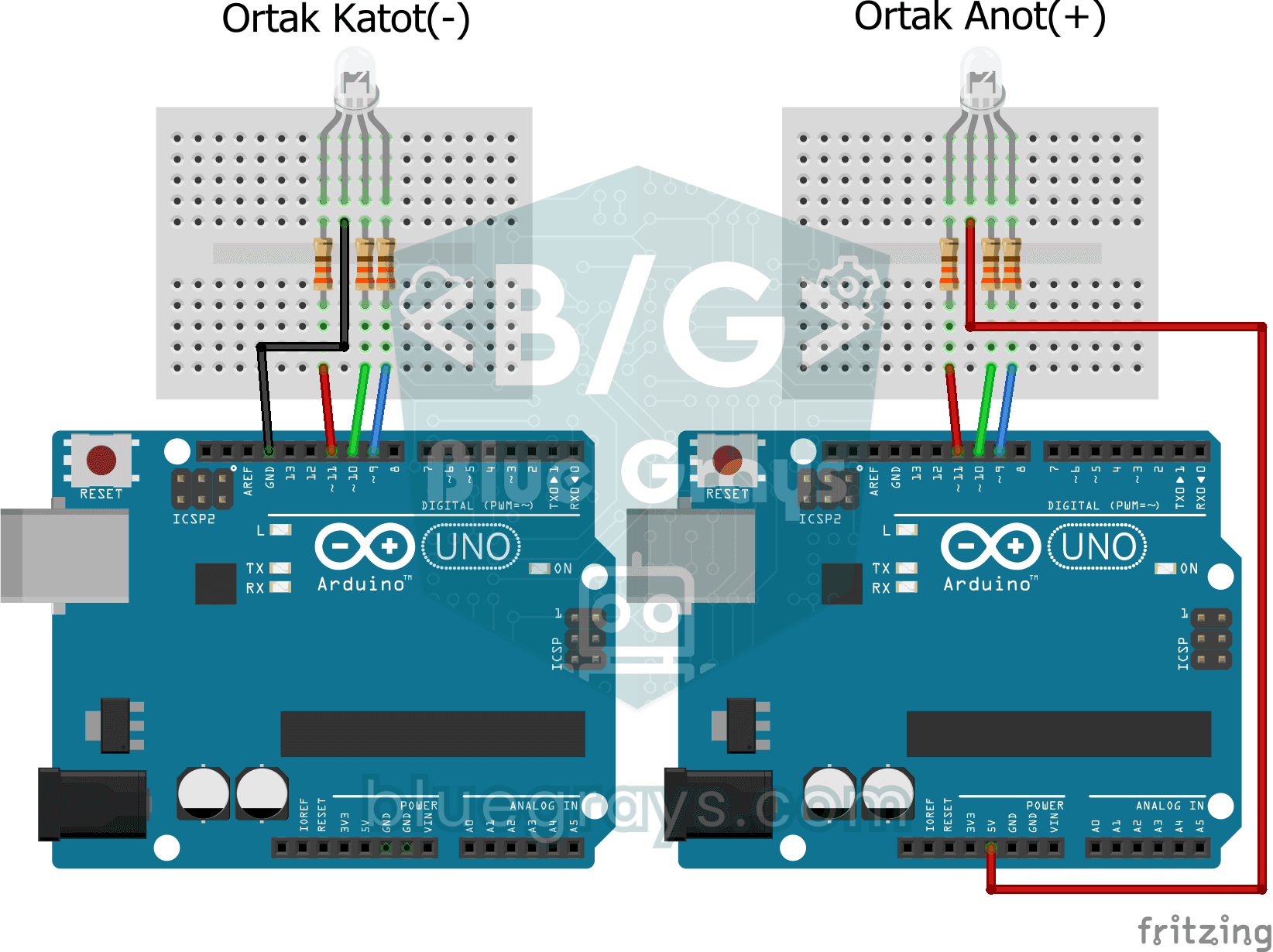
Smooth Color Transition with RGB Led
A single RGB LED drifts slowly from red to green, green to blue and back to red, looping through the rainbow without ever stopping.

ESP32 RGB LED Control
Unlimited color generation with a single RGB LED instead of 3 separate LEDs. As in Arduino, we make a rainbow transition by setting the R/G/B values with analogWrite(). Color theory (such as red+green=yellow) is seen practically.

ESP32 Color Mixer Light (3 Potentiometers + RGB LED + OLED)
A smart color-mixer lamp: turn 3 potentiometers on the ESP32 and mix any color you like! As you turn the red, green and blue potentiometers, the common-cathode RGB LED changes color instantly. The SSD1306 OLED display shows each channel's 0-255 value, fill bars and the HEX web color code (like #FF8040) live.

TCRT5000 Black and White Surface Detection
With the little sensor that acts as the eye of line-following robots, you can tell whether the floor is black or white.
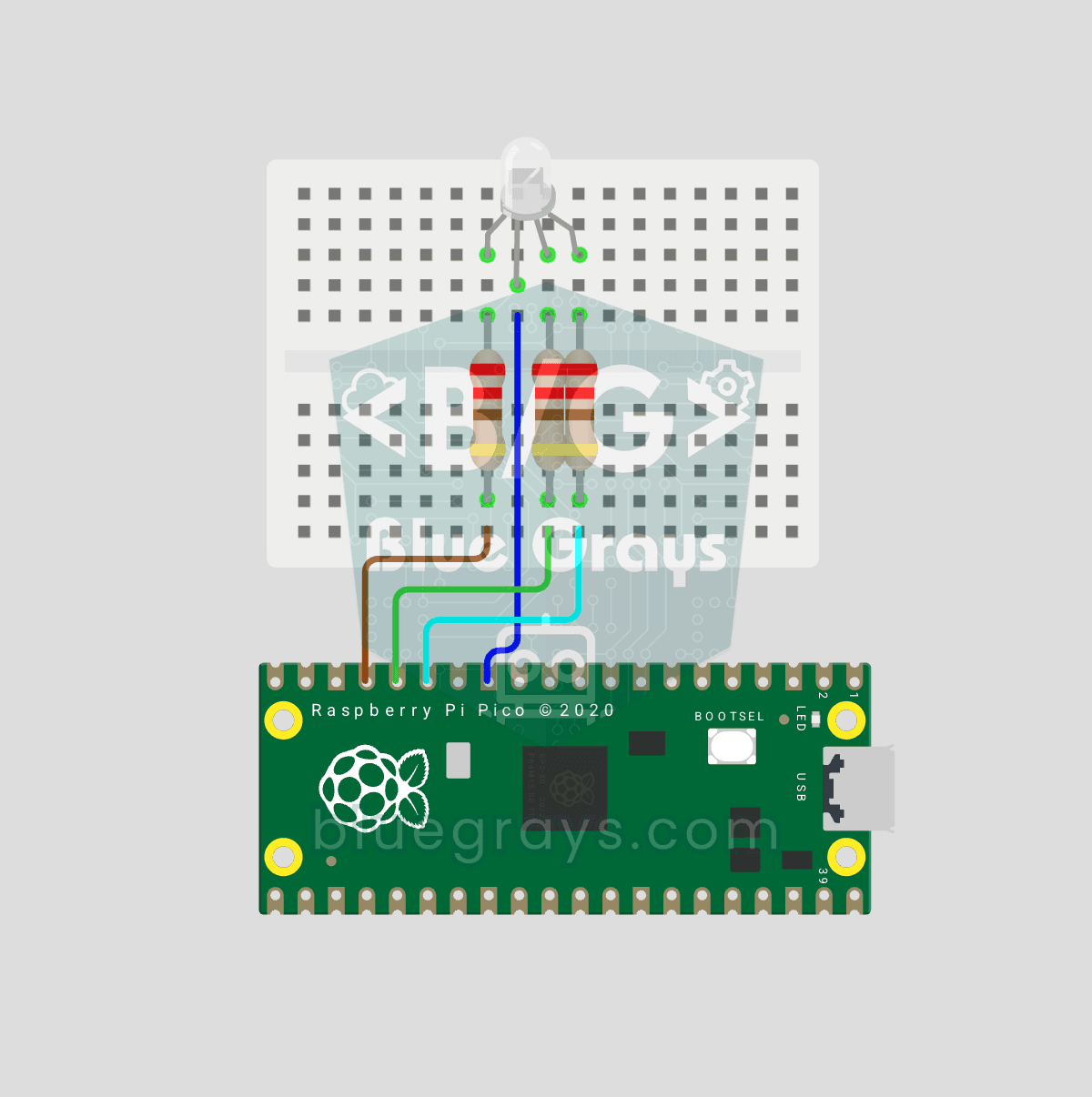
Raspberry Pi Pico RGB LED Color Cycle (3-Channel PWM)
One LED, millions of colors! An RGB LED actually holds 3 separate LEDs: red, green and blue. Set the brightness of each one separately with the Pico's 3 PWM channels and the colors mix: red + green = yellow, green + blue = cyan, all three = white. In this project the LED cycles through 8 colors.