
MG90S Servo Arduino Guide: SG90 Comparison, Wiring, Calibration
Using an MG90S servo with Arduino: metal gears vs SG90, 2.2 kg·cm torque, wire colours, 500–2400 µs calibration, power supply and Uno, ESP32, Pico code.

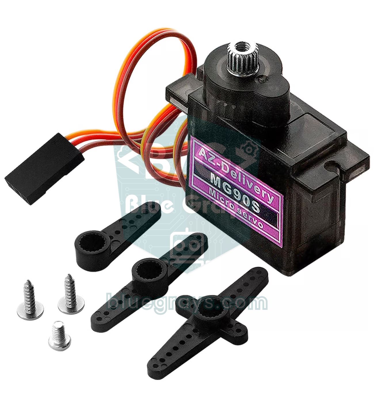
The MG90S servo is a micro servo the same size as the SG90 but with metal gears: its 13.4 g body delivers 1.8 kg·cm of stall torque at 4.8 V and 2.2 kg·cm at 6 V, and it survives knocks, crashes of the arm and accidental turning by hand far better than the plastic-geared SG90. Using an MG90S servo with Arduino is just as easy as an SG90: the same three wires, the same Servo library and the same 50 Hz signal. The differences are in the details; it draws a little more current, its pulse range varies from unit to unit and it needs calibrating if you want accurate angles.
In this guide you'll compare the MG90S's specifications with the SG90 and MG996R and look at the wire colours and wiring for the Arduino Uno, ESP32 and Raspberry Pi Pico. Then you'll learn how the 500–2400 µs pulse range turns into an angle, how to find your own servo's limits from the Serial Monitor and how to correct angle errors with three-point calibration. The last sections cover sizing a separate power supply, phone control with an ESP32, Pico MicroPython code and which joints of a robot arm suit the MG90S.
What is the MG90S servo and how does it work?
Inside the MG90S there's a small DC motor, a metal gearbox that slows the motor down and multiplies its torque, a potentiometer that measures the angle of the output shaft and a control board that runs it all. Every 20 ms (50 Hz) the board measures the width of the pulse arriving on the signal wire, compares it with the angle reported by the potentiometer and drives the motor until the difference is gone. A pulse of about 1500 µs means the centre position; shorter pulses turn the shaft one way, longer ones the other way. The 5 µs dead band in the datasheet is half the SG90's 10 µs, so the MG90S reacts to smaller pulse changes and holds its position more precisely. We covered the basics of how servos work in What Is a Servo Motor?.
| Feature | Value |
|---|---|
| Operating voltage | 4.8–6 V |
| Stall torque | 1.8 kg·cm (4.8 V), 2.2 kg·cm (6 V) ≈ 0.18–0.22 N·m |
| Speed (per 60°) | 0.10 s (4.8 V), 0.08 s (6 V) |
| Idle current | About 5–10 mA (shaft still, no load) |
| Running current | About 120–250 mA (no load) |
| Stall current | About 0.7–1 A |
| Dead band | 5 µs |
| Rotation | About 180° with 500–2400 µs (varies from unit to unit) |
| Signal | 50 Hz (20 ms period), position set by pulse width |
| Gears | Metal gears, bearing on the output shaft |
| Weight and size | 13.4 g, 22.8 × 12.2 × 28.5 mm |
| Cable | About 25 cm; brown GND, red positive, orange signal |
| Operating temperature | 0–55 °C |
MG90S vs SG90: gears, torque and current
From the outside the two servos are almost identical: the mounting holes, body width and horns are compatible, so you can drop an MG90S straight into a mount designed for an SG90. The real difference is inside. The SG90's plastic gears skip teeth and break when the arm hits something or the shaft is forced by hand; the MG90S's metal gears usually shrug off the same knock. At 6 V the torque rises from 1.8 to 2.2 kg·cm and the speed drops to 0.08 seconds per 60 degrees. In return the MG90S is about 4.4 grams heavier, draws a little more current when stalled and usually costs two to three times as much as an SG90. Metal gears can also have a little backlash; on a precise arm this shows up as a degree or two of play when the load changes direction.
| Feature | SG90 | MG90S | MG996R |
|---|---|---|---|
| Gears | Plastic | Metal | Metal, dual bearings |
| Stall torque | 1.8 kg·cm (4.8 V) | 1.8 kg·cm (4.8 V), 2.2 kg·cm (6 V) | 9.4 kg·cm (4.8 V), 11 kg·cm (6 V) |
| Speed (per 60°) | 0.10 s (4.8 V) | 0.10 s (4.8 V), 0.08 s (6 V) | 0.17 s (4.8 V), 0.14 s (6 V) |
| Dead band | 10 µs | 5 µs | 5 µs |
| Weight | 9 g | 13.4 g | 55 g |
| Size | 22.2 × 11.8 × 31 mm | 22.8 × 12.2 × 28.5 mm | 40.7 × 19.7 × 42.9 mm |
| Operating voltage | 4.8–6 V | 4.8–6 V | 4.8–7.2 V |
| Stall current | About 0.6–0.75 A | About 0.7–1 A | 2.5 A (6 V) |
| Shock resistance | Low, gears strip easily | Good | Very good |
| From the Arduino's 5V pin | One servo, light load | One servo, light load | No, always an external supply |
| Typical use | First experiments, light lids | Wrist, gripper, pan-tilt, small robots | Robot arm shoulder, heavy lid, steering |
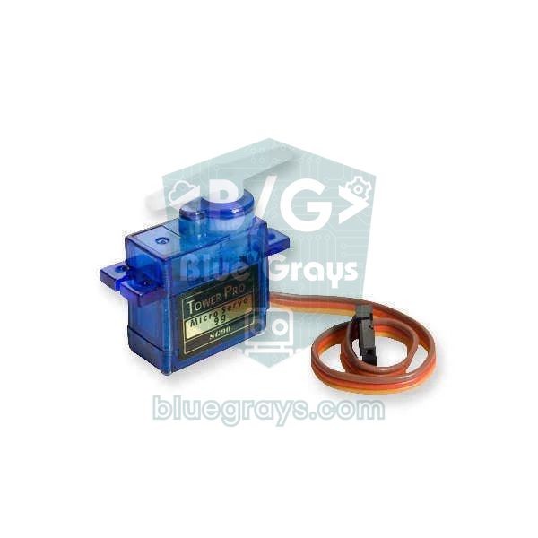
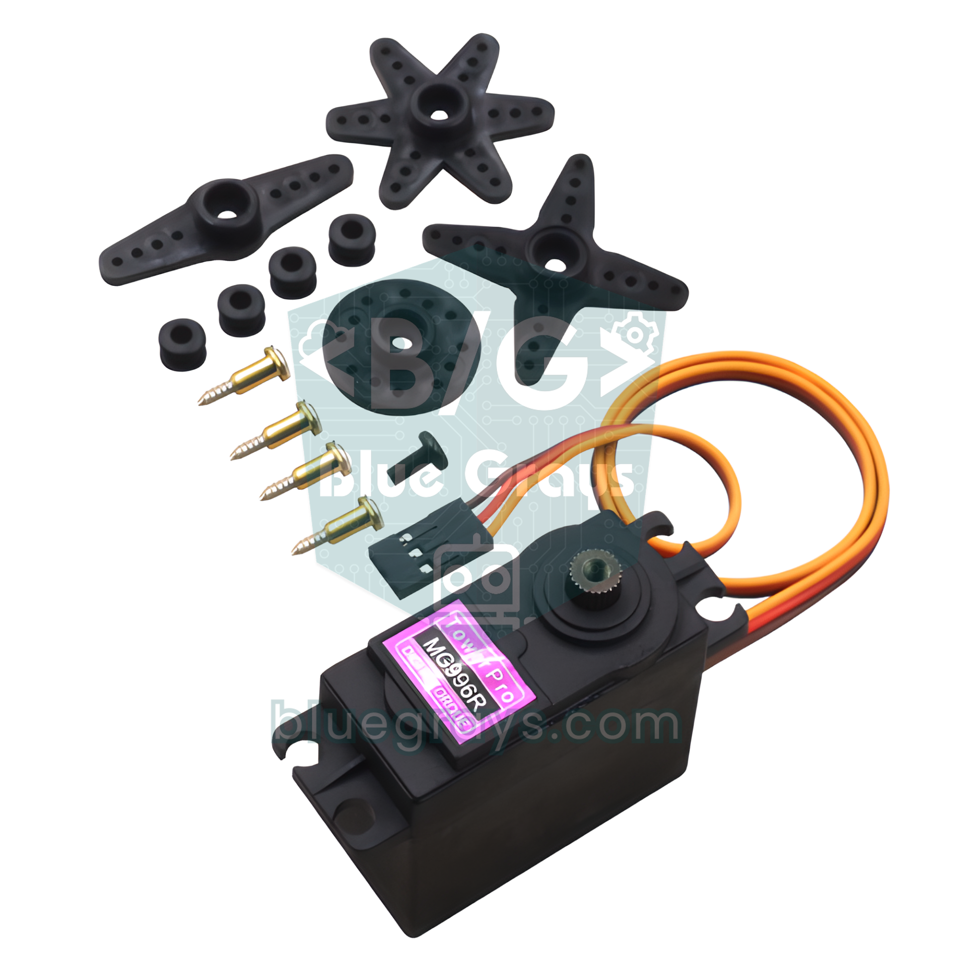
To choose, first work out the torque you need: torque is the weight of the load multiplied by its distance from the shaft. A 100 g load 5 cm from the shaft needs 0.1 × 5 = 0.5 kg·cm. At 5 V the MG90S gives about 2 kg·cm, but that's the stall limit, where the shaft stops; in continuous use, staying at no more than half of it, around 1 kg·cm, keeps the servo cool and makes the gears last longer. By that rule the MG90S comfortably carries up to 200 g at the end of a 5 cm arm and up to 100 g at the end of a 10 cm arm. If you need more than 1 kg·cm, move up to the MG996R servo; if you're just experimenting or turning a part that weighs a few grams, an SG90 is enough.
MG90S wire colours and wiring
The MG90S's three wires follow the TowerPro colour scheme. Some manufacturers pick different colours, but the order is almost always the same, with positive in the middle. If you plug the connector in backwards the servo usually isn't damaged, it just doesn't work; still, fix it straight away, because the servo's ground current then tries to flow through the Arduino's signal pin.
| Wire (TowerPro) | Function | Other brands | Connects to |
|---|---|---|---|
| Brown | GND (negative) | Black | Supply negative and Arduino GND |
| Red | Positive (4.8–6 V) | Red | 5 V or external 5–6 V positive |
| Orange | Signal (PWM) | Yellow or white | A digital pin on the board |
| Connection | Arduino Uno | ESP32 | Raspberry Pi Pico |
|---|---|---|---|
| Orange (signal) | D9 | GPIO 18 | GP15 |
| Red (positive): one servo, light load | 5V pin | 5V (VIN) pin, from USB | VBUS pin (5 V from USB) |
| Red (positive): load or several servos | External 5–6 V | External 5–6 V | External 5–6 V |
| Brown (GND) | GND and supply negative | GND and supply negative | GND and supply negative |
| Potentiometer (Uno example) | Wiper to A0, outer legs to 5V and GND | — | — |
| Second servo (Pico example) | — | — | GP14 |
Separate power: how many servos, how much current?
An MG90S draws 120–250 mA when moving without load, but in the first milliseconds of every start and when the shaft is forced, the current jumps to 0.7–1 A. With more servos these peaks stack up. Take the wiring into account too: breadboard contacts and thin jumper wires easily add up to 0.2 Ω. Work it out with Ohm's law and at a 3.2 A peak from four servos starting together, 3.2 × 0.2 = 0.64 V is lost in the wires alone; the 5 V supply reaches the servos as 4.4 V, and they weaken and jitter. Distributing servo power through a screw terminal or a soldered rail instead of the breadboard cuts this loss dramatically.
| Number of servos | While moving | Worst case (all stalled) | Recommended supply |
|---|---|---|---|
| 1 | 0.12–0.25 A | About 1 A | Arduino 5V for no-load tests, 5 V 1 A under load |
| 2 (pan-tilt) | 0.25–0.5 A | 2 A | 5 V, 2 A |
| 4 (small robot arm) | 0.5–1 A | 4 A | 5 V, 3–4 A |
| 6 | 0.75–1.5 A | 6 A | 5–6 V, 5 A and code that moves the servos one at a time |
| 16 (PCA9685) | 2–4 A | 16 A | 5–6 V switching supply, 10 A or more |
- Choose the supply: use a 5 V switching adapter or 4 AA NiMH cells (4.8 V). Fresh alkaline cells can reach 1.6 V each, so a 4-cell holder may give 6.4 V, slightly above the MG90S's limit.
- Feed positive to the servo: connect the supply's positive to the servo's red wire; don't connect it to the Arduino's 5V pin.
- Join the grounds: connect the supply's negative to both the servo's brown wire and the Arduino's GND pin; without a common ground the servo can't read the pulses correctly.
- Add a capacitor: put a 470 µF / 16 V electrolytic capacitor across the servo supply, close to the servos; with several servos add about 100 µF per servo. The striped leg goes to negative.
- Connect the signal: connect the orange wire to the Uno's D9 pin and power the Arduino separately from USB or its DC jack.
The 500–2400 µs pulse range and the Servo library
With the Servo library that ships with the Arduino IDE, writing servo.attach(9) gives a default range of 544–2400 µs, and write(0) and write(180) are mapped to those two ends. Most MG90S servos need a pulse shorter than 544 µs for 0 degrees, so with the default setting the servo falls a few degrees short at one end. Specifying the range with servo.attach(9, 500, 2400) fixes that. This detail matters because writeMicroseconds() can't go outside the limits given to attach either; without them, the 500 µs you write is silently raised to 544. Across 500–2400 µs one degree is about 1900 / 180 ≈ 10.6 µs. Because the MG90S's dead band is 5 µs, you can even make half-degree steps with writeMicroseconds().
| Angle | attach(9) default (544–2400) | attach(9, 500, 2400) | Note |
|---|---|---|---|
| 0° | 544 µs | 500 µs | A few degrees' difference at the end |
| 45° | 1008 µs | 975 µs | — |
| 90° | 1472 µs | 1450 µs | The real centre is usually between 1450 and 1550 µs |
| 135° | 1936 µs | 1925 µs | — |
| 180° | 2400 µs | 2400 µs | Narrow it if it hits the mechanical stop |
The values in the table are calculated; on a real servo the pulse needed for 90 degrees may be 1500 or 1520 µs instead of 1450. Some datasheets claim 1000–2000 µs gives the full travel, but in practice an MG90S only turns 90–100 degrees over that range. If you push the pulse past the mechanical limit, the servo presses against its internal stop, buzzes, draws stall current and heats up; because metal gears bear this strain silently, you won't notice the problem as quickly as with an SG90. That's why the first job is to measure your own servo's limits.
Angle calibration: find your own MG90S's limits
The code below moves the servo in 10 µs steps with characters you type in the Serial Monitor. + lengthens the pulse, - shortens it and c returns to the centre (1500 µs); n saves the current value as the lower limit and x as the upper limit. After each save the code prints a ready-made attach line for your later sketches. To take several steps at once, type +++++ and press Enter; the servo moves five steps, or 50 µs.
1#include <Servo.h>
2
3const byte SERVO_PIN = 9;          // turuncu sinyal kablosu / orange signal wire
4const int STEP_US = 10;            // her + ya da - için 10 µs / 10 µs per + or -
5
6Servo servo;
7int pulseUs = 1500;                // ortadan başla / start at the center
8int minUs = 1000;                  // bulunacak alt sınır / lower limit to find
9int maxUs = 2000;                  // bulunacak üst sınır / upper limit to find
10
11void printPulse() {
12  Serial.print(F("Darbe / pulse: "));
13  Serial.print(pulseUs);
14  Serial.println(F(" us"));
15}
16
17void setup() {
18  Serial.begin(115200);
19  servo.writeMicroseconds(pulseUs);      // önce darbe, sonra attach / pulse first, then attach
20  servo.attach(SERVO_PIN, 500, 2500);    // geniş aralık: sınırı sen bulacaksın / wide range: you find the limits
21  Serial.println(F("+ / - : 10 us | c: 1500 us | n: min | x: max"));
22  printPulse();
23}
24
25void loop() {
26  if (!Serial.available()) return;
27  char key = Serial.read();
28  if (key == '+') pulseUs += STEP_US;
29  else if (key == '-') pulseUs -= STEP_US;
30  else if (key == 'c') pulseUs = 1500;
31  else if (key == 'n') minUs = pulseUs;    // alt sınırı kaydet / save the lower limit
32  else if (key == 'x') maxUs = pulseUs;    // üst sınırı kaydet / save the upper limit
33  else return;                             // Enter ve diğer tuşları yok say / ignore Enter and other keys
34
35  pulseUs = constrain(pulseUs, 500, 2500);
36  servo.writeMicroseconds(pulseUs);
37  printPulse();
38
39  if (key == 'n' || key == 'x') {          // hazır attach satırı / ready-made attach line
40    Serial.print(F("servo.attach(9, "));
41    Serial.print(minUs);
42    Serial.print(F(", "));
43    Serial.print(maxUs);
44    Serial.println(F(");"));
45  }
46}- Connect the servo without a load, upload the code and open the Serial Monitor at 115200 baud.
- Type c and press Enter; the servo goes to 1500 µs. Fit the horn on the spline position closest to your mechanism's centre.
- Move towards the lower end with -. When the servo stops turning, buzzes or jitters, go back 3–4 steps (30–40 µs) and type n.
- Do the same for the upper end with + and type x. Note down the servo.attach(9, MIN, MAX) line shown in the Serial Monitor.
- Find 90 degrees with a protractor drawn on paper or printed out: save the pulse at which the horn stands exactly upright as US_90.
Because of the teeth on the servo shaft, you can only fit the horn in fixed steps, so it rarely sits exactly in the centre and you correct the few degrees in between in software. On top of that, a servo's pulse-to-angle relationship isn't perfectly linear: a two-point mapping that nails 0 and 180 degrees can drift by 3–5 degrees in the middle. Three-point calibration removes this error: you use the three pulses you measured for 0, 90 and 180 degrees and call the map() function separately for each half. The code below uses this method to pass the angle read from a potentiometer on A0 to the servo.
1#include <Servo.h>
2
3const byte SERVO_PIN = 9;          // turuncu kablo / orange wire
4const byte POT_PIN = A0;           // potansiyometre orta bacağı / potentiometer wiper
5
6// Kalibrasyonda ölçtüğün üç nokta / the three points you measured
7const int US_0 = 520;              // 0 derece / 0 degrees
8const int US_90 = 1480;            // korna tam dik / horn exactly upright
9const int US_180 = 2380;           // 180 derece / 180 degrees
10
11Servo servo;
12float smoothAngle = 90;            // süzülmüş açı / filtered angle
13int lastAngle = -1;
14
15int angleToUs(int angle) {
16  angle = constrain(angle, 0, 180);
17  if (angle <= 90) return map(angle, 0, 90, US_0, US_90);   // alt yarı / lower half
18  return map(angle, 90, 180, US_90, US_180);                // üst yarı / upper half
19}
20
21void setup() {
22  servo.writeMicroseconds(angleToUs(90));   // açılışta ortada başla / start centered
23  servo.attach(SERVO_PIN, US_0, US_180);
24}
25
26void loop() {
27  int target = map(analogRead(POT_PIN), 0, 1023, 0, 180);
28  smoothAngle += (target - smoothAngle) * 0.15;   // gürültüyü süz / filter the noise
29  int angle = (int)(smoothAngle + 0.5);
30  if (abs(angle - lastAngle) >= 2) {             // 2 derecelik ölü bant / 2-degree deadband
31    servo.writeMicroseconds(angleToUs(angle));
32    lastAngle = angle;
33  }
34  delay(15);
35}
Replace US_0, US_90 and US_180 with your own measurements. angleToUs() maps 0–90 between the first two points and 90–180 between the last two, so the position where the horn stands upright really is 90 degrees. Using writeMicroseconds() also avoids write() rounding to whole degrees. The few counts of noise in the potentiometer reading are suppressed by a simple filter with a factor of 0.15 and a 2-degree dead band; without the dead band the servo keeps twitching in place. We cover the other causes of jitter in detail in servo jitter problem. On the Uno the Servo library uses Timer1, so analogWrite() doesn't work on pins D9 and D10 while a servo is attached.
MG90S with ESP32: control from your phone with a slider
The standard Arduino Servo library doesn't work on the ESP32; install the ESP32Servo library from the Library Manager. It works with both the 2.x and 3.x versions of the ESP32 core, takes the period with setPeriodHertz(50) and doesn't accept limits outside 500–2500 µs. The ESP32's signal output is 3.3 V, and virtually every MG90S reads it without trouble. The code below connects the ESP32 to your Wi-Fi network; open the IP address shown in the Serial Monitor on a phone on the same network and you'll see a slider, and the moment you release it the servo turns to that angle.
1#include <WiFi.h>
2#include <WebServer.h>
3#include <ESP32Servo.h>
4
5const char* ssid = "AgAdi"; // Wi-Fi adın / your Wi-Fi name
6const char* password = "Sifre123"; // Wi-Fi şifren / your Wi-Fi password
7const int SERVO_PIN = 18; // turuncu kablo / orange wire
8const int MIN_US = 500; // kalibrasyon değerlerin / your calibration values
9const int MAX_US = 2400;
10
11WebServer server(80);
12Servo servo;
13int currentAngle = 90;
14
15const char PAGE[] = R"rawliteral(<!DOCTYPE html><html><head>
16<meta name="viewport" content="width=device-width,initial-scale=1"><title>MG90S</title></head>
17<body style="font-family:sans-serif;text-align:center">
18<h2>MG90S: <span id="v">90</span>°</h2>
19<input id="s" type="range" min="0" max="180" value="90" style="width:90%">
20<script>
21const s = document.getElementById('s'), v = document.getElementById('v');
22s.oninput = () => v.textContent = s.value;
23s.onchange = () => fetch('/set?a=' + s.value);
24</script></body></html>)rawliteral";
25
26void handleRoot() {
27 server.send(200, "text/html", PAGE);
28}
29
30void handleSet() {
31 if (server.hasArg("a")) {
32 currentAngle = constrain(server.arg("a").toInt(), 0, 180); // 0–180 ile sınırla / clamp to 0–180
33 servo.write(currentAngle);
34 }
35 server.send(200, "text/plain", String(currentAngle));
36}
37
38void setup() {
39 Serial.begin(115200);
40 servo.setPeriodHertz(50); // 50 Hz servo sinyali / 50 Hz servo signal
41 servo.attach(SERVO_PIN, MIN_US, MAX_US);
42 servo.write(currentAngle);
43
44 WiFi.begin(ssid, password);
45 while (WiFi.status() != WL_CONNECTED) delay(300);
46 Serial.print(F("IP: "));
47 Serial.println(WiFi.localIP()); // bu adresi telefonda aç / open this address on your phone
48
49 server.on("/", handleRoot);
50 server.on("/set", handleSet);
51 server.begin();
52}
53
54void loop() {
55 server.handleClient();
56}When the ESP32 switches on Wi-Fi it briefly draws up to 250 mA; if the servo's start-up current lands on the same USB line, the board prints "Brownout detector was triggered" and restarts. Power the servo from a separate 5 V supply and join the grounds; details are in ESP32 brownout error. GPIO 13, 18, 19, 23, 25, 26 and 27 are good choices for the signal; don't use GPIO 6–11, which are tied to the flash, or input-only 34–39.
MG90S with Raspberry Pi Pico (MicroPython)
On the Raspberry Pi Pico you don't need any extra library: you set the PWM to 50 Hz and give the pulse width in nanoseconds with duty_ns(). The small MicroServo class below stores each servo's own calibration values and moves one degree at a time for smooth motion. In the example a robot arm's wrist is on GP15 and its gripper on GP14. On the Pico these two pins share the same PWM slice (slice 7), so they share a frequency; that's fine because both use 50 Hz, but if you set another pin on the same slice to 1 kHz for LED brightness, the servo goes wrong too. For two servos use an external 5 V supply instead of VBUS and join the grounds.
1from machine import Pin, PWM
2import time
3
4class MicroServo:
5    def __init__(self, pin, min_us=500, max_us=2400):
6        self.pwm = PWM(Pin(pin))
7        self.pwm.freq(50)                  # 50 Hz = 20 ms periyot / 20 ms period
8        self.min_us = min_us               # bu servonun kalibrasyonu / this servo's calibration
9        self.max_us = max_us
10        self.angle = None
11
12    def write(self, angle):
13        angle = max(0, min(180, angle))   # 0–180 ile sınırla / clamp to 0–180
14        us = self.min_us + (self.max_us - self.min_us) * angle / 180
15        self.pwm.duty_ns(int(us * 1000))  # µs -> ns
16        self.angle = angle
17
18    def move_to(self, target, ms_per_degree=10):
19        if self.angle is None:            # ilk komut: doğrudan git / first command: go directly
20            self.write(target)
21            return
22        step = 1 if target > self.angle else -1
23        for a in range(int(self.angle), int(target) + step, step):
24            self.write(a)                 # derece derece ilerle / move degree by degree
25            time.sleep_ms(ms_per_degree)
26
27    def off(self):
28        self.pwm.duty_ns(0)               # sinyali kes, servo serbest / stop the signal, servo goes limp
29
30wrist = MicroServo(15, 520, 2380)        # bilek GP15 / wrist on GP15
31gripper = MicroServo(14, 600, 2300)      # kıskaç GP14, aynı PWM dilimi / gripper on GP14, same PWM slice
32
33wrist.write(90)
34gripper.write(20)
35time.sleep(1)
36
37while True:
38    gripper.move_to(70)                  # kıskacı kapat / close the gripper
39    wrist.move_to(150)
40    time.sleep(0.5)
41    wrist.move_to(30)
42    gripper.move_to(20)                  # kıskacı aç / open the gripper
43    time.sleep(1)
MG90S in a robot arm: which joint does it suit?
Small 4-axis robot arms made of acrylic or 3D prints are usually built with four micro servos, and in these arms the MG90S lasts far longer than the SG90: when the arm hits something or the gripper is forced by hand, the plastic gears are the first thing to break. On a bigger arm, the MG90S is only used in the end joints. The maths is simple: multiply the weight of each part after the joint by its distance from the joint's shaft and add them up. A 40 g gripper at 6 cm and a 50 g object at 8 cm put 0.04 × 6 + 0.05 × 8 = 0.64 kg·cm on the wrist servo, below the MG90S's safe limit of about 1 kg·cm at 5 V.
| Joint | Typical load | Is the MG90S suitable? |
|---|---|---|
| Base (rotation) | Low if the arm's weight sits on a bearing | Yes on small arms, MG996R on big ones |
| Shoulder | Highest, 2–5 kg·cm | Only on very light arms; usually MG996R |
| Elbow | Medium, 1–3 kg·cm | Yes on short arms |
| Wrist | Low, 0.3–1 kg·cm | Yes, ideal |
| Gripper | Low, but risk of constant squeezing | Yes; limit the closing angle to the object |
The most common gripper mistake is sending the servo further than the angle at which it grips the object. Because it can't reach the target, the servo draws stall current continuously, heats up, and within a few minutes the motor or the control board can be damaged. Set the closing angle to the point where the jaws just touch the object, or back the angle off a few degrees once it's holding. You'll find the full torque calculation and how to build a 6-axis arm in the Arduino robot arm guide; if you want to drive more than six servos from one board, a PCA9685 servo driver makes the job easier.
MG90S project ideas
- Pan-tilt camera mount: turn an ESP32-CAM module horizontally and vertically with two MG90S servos; the metal gears cope with the shaking.
- Arduino radar: sweep an HC-SR04 sensor from 0 to 180 degrees with an MG90S and draw a radar screen; the build is in Arduino radar project.
- Smart bin: a smart bin that opens a light lid when a hand comes close.
- Automatic pet feeder: a pet feeder that opens and closes a small flap at set times.
- Obstacle-avoiding robot: a neck servo that turns the distance sensor left and right; see the obstacle-avoiding robot guide.
- Mini solar tracker: find the direction of the light with two LDRs and turn a small panel with an MG90S; details in solar tracker.
- Jobs that need continuous rotation: for a wheel or a conveyor, use a 360-degree servo instead of the MG90S.
Common mistakes and how to fix them
| Symptom | Likely cause | Fix |
|---|---|---|
| The servo falls a few degrees short at one end | The default 544–2400 µs range | Write attach(9, 500, 2400) and calibrate |
| It buzzes and heats up at the end | The pulse goes past the mechanical limit | Narrow it to the MIN and MAX values you found |
| The Arduino resets when the servo moves | The servo is powered from USB via the 5V pin | External 5 V supply, common GND and a 470 µF capacitor |
| It jitters while standing still | Weak supply, long thin wires or potentiometer noise | Thick wires, a capacitor, a filter and a dead band |
| No response at all, or random movement | The external supply's GND isn't connected to the Arduino | Connect the supply's negative to the Arduino's GND |
| Clicking under load, the shaft slips | A gear tooth has broken or the horn screw is loose | Replace the gear set, tighten the centre screw |
| Much less torque than expected, the servo weighs 9 g | A copy with plastic gears | Weigh the servo: a genuine MG90S is about 13–14 g |
| The servo jumps suddenly at power-up | attach() sends 1500 µs as the first pulse | Give the starting pulse with writeMicroseconds() before attach() |
The MG90S is the right choice for any project that wants a tougher, slightly stronger servo while staying the size of an SG90. Remember the rules: an external 5 V supply for anything but light loads, a common GND, a capacitor close to the servo, a pulse range that starts at 500–2400 µs and is narrowed by calibration, and a limited closing angle on grippers. In the BlueGrays app you'll find servo control with a potentiometer and a joystick, an ESP32 RFID door lock with a servo and a 32-servo choreography project, each with step-by-step circuit diagrams and ready-to-use code.
Frequently asked questions
What is the difference between the MG90S and SG90?
They're the same size with the same wiring, but the MG90S has metal gears and gives 2.2 kg·cm of torque at 6 V, while the SG90's plastic gears give around 1.8 kg·cm and strip easily under shock. The MG90S weighs about 13.4 g against the SG90's 9 g and draws a little more current when stalled. There's no difference in code; both work with the same Servo library.
How much weight can an MG90S servo lift?
The MG90S's stall torque is 1.8 kg·cm at 4.8 V and 2.2 kg·cm at 6 V, so 1 cm from the shaft it can only just hold about 2 kg. For continuous use, count on half the torque: about 200 g at the end of a 5 cm arm and about 100 g at the end of a 10 cm arm.
Can I power an MG90S from the Arduino 5V pin?
For no-load tests, a single MG90S works from the Arduino's 5V pin. But when the servo is forced, a current close to 1 A exceeds USB's 500 mA limit and the Arduino resets. For projects with a load or several servos, use an external 5 V supply and join the grounds.
Is the MG90S 180 or 360 degrees?
The standard MG90S turns about 180 degrees; the full travel usually needs 500–2400 µs pulses, and the limits vary from unit to unit. Continuous-rotation 360-degree versions are also sold, but with those you control speed and direction, not angle.
Why is my MG90S servo jittering or buzzing?
The most common cause is a weak supply: a servo powered from USB pulls the voltage down as it starts. If it buzzes at the ends, the pulse range goes past the mechanical limit, so narrow it by calibrating. If it jitters under potentiometer control, filter the reading and add a 1–2 degree dead band.
Does the MG90S work with an ESP32 and a 3.3 V signal?
Yes. The MG90S's control board reads a 3.3 V signal without trouble; the ESP32Servo library on the ESP32 or MicroPython's PWM class on the Pico is all you need. The servo's power should still be 5 V; don't power it from the 3.3 V pin.
Projects to build after reading this
See all projects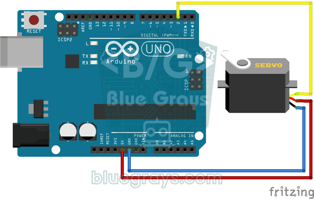
Using a Servo Motor
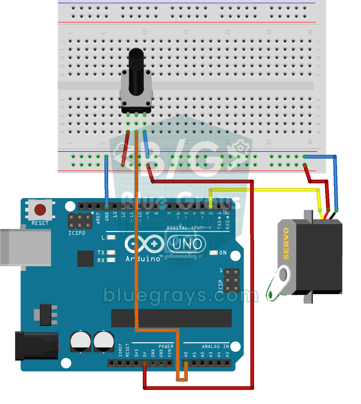
The arm of a small servo motor turns to three positions in turn: all the way to the start, right to the middle and all the way to the end, waiting two seconds at each stop.
Servo Motor Operation with Potentiometer
As you turn the potentiometer knob, the servo motor's arm turns right along with it: one end of the knob means zero degrees, the other end means half a turn.
Servo Control with Joystick
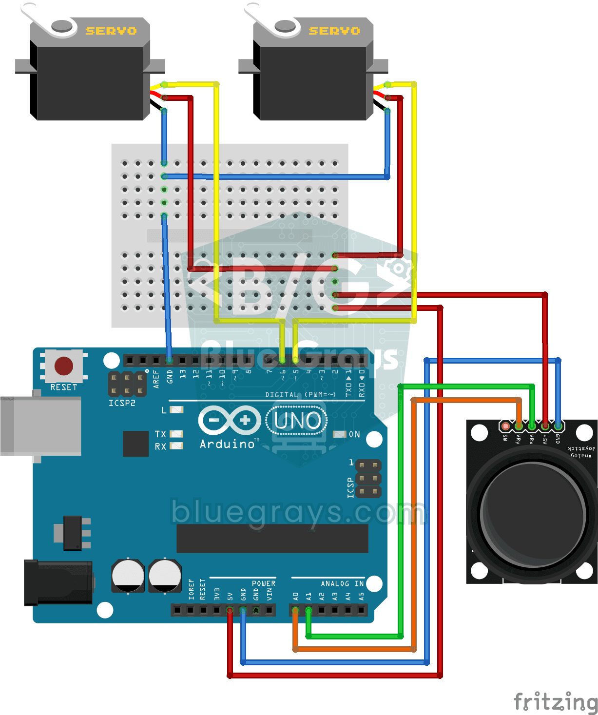
Steer two motors with a joystick, just like turning a security camera. Push the stick left or right and the bottom servo motor slowly turns, push it up or down and the top servo tilts up and down…

ESP32 Servo Motor (Potentiometer Control)
In this project, we control an SG90 servo motor using a potentiometer. We adjust the servo angle by mapping the analog value read from the potentiometer to the 0–180-degree range. The ESP32Servo library generates servo signals on suitable output-capable GPIO pins of the ESP32; this project uses GPIO 18. This is a fundamental control method for robotic arms, camera gimbals, and automatic door mechanisms.

ESP32 RFID Door Lock (RC522 + Servo + OLED + Buzzer + LED)
We build a smart door lock with an ESP32, an RC522 RFID module, an SG90 servo, an SSD1306 OLED display, an active buzzer and 2 LEDs. When a card is scanned, its UID is checked against the authorized cards defined in the code; if it matches, the servo unlocks (green LED + 2 short beeps) and locks again after 5 seconds. An unknown card lights the red LED, gives 3 quick beeps and shows its UID on the OLED.

Servo Circle Choreography - Animated Patterns with 32 Servos
A visual animation project driven by 32 servo motors arranged in a circle on an Arduino Mega. The servos are managed in a single array, connected to the Mega's pins 22–53, and perform four motion sequences: a chaotic jitter at random angles, a synchronized sweep, a wave travelling around the circle and a compass needle swinging left and right.

Obstacle Avoidance Robot
How about building a smart vehicle that finds its own way? The Obstacle Avoidance Robot constantly scans its surroundings thanks to the ultrasonic sensor in front of it.