
MAX6675 Arduino Thermocouple Guide: K-Type up to 1000 °C
How do you use the MAX6675 with Arduino? SPI wiring, library, K-type thermocouple 0–1023 °C, LCD, stove, oven and soldering examples, ESP32 and Pico code.

The MAX6675 is a converter chip that turns the millivolt signal of a K-type thermocouple directly into a digital temperature value. With the MAX6675 and Arduino you can measure temperatures from 0 to 1023.75 °C in 0.25 °C steps. Where sensors like the DHT11 or DS18B20 only survive up to 50–125 °C, such as a stove pipe, a kitchen oven, a pizza oven, a soldering iron tip or an exhaust pipe, the thermocouple does the job. The module connects over SPI with just three signal wires (SCK, CS, SO) and is read in a single line with its library.
In this post you'll see how a thermocouple works, what is inside the 16-bit data the MAX6675 sends, and the wiring for Arduino Uno, ESP32 and Raspberry Pi Pico, step by step. Then we'll write a temperature alarm with an LCD for a stove pipe and a simple relay thermostat for an oven or soldering station, and finally fix the most common problems such as "why do I read NAN?" or "why does the value drop as it heats up?".
What is the MAX6675 and a thermocouple, and how do they work?
A thermocouple is made of two different metal wires welded together at one end. When there is a temperature difference between this welded point (the hot junction) and the other ends of the wires (the cold junction), a very small voltage appears across the wires; this is called the Seebeck effect. In a K-type thermocouple the positive wire is chromel (nickel-chromium) and the negative wire is alumel (nickel-aluminium), and the voltage produced is about 41 µV/°C. So a 100 °C difference gives a signal of only about 4 mV, which you can't measure directly with the 10-bit ADC of an Arduino Uno (one step is about 4.9 mV). On top of that, a thermocouple measures not the absolute temperature but the difference between its two ends, so you also need to know the temperature of the cold junction, that is, the surroundings of the module. The MAX6675 does exactly these two jobs: it amplifies the microvolt signal and converts it to digital with a 12-bit ADC, and it performs cold-junction compensation automatically with its built-in temperature sensor. All that's left for you is reading 16 bits over SPI. According to the datasheet the chip's own error is a few LSB, around ±1.5–2 °C, and the thermocouple's own tolerance (±2.5 °C or 0.75% of the reading for a standard K type) adds to that.
| Feature | Value |
|---|---|
| Converter chip | MAX6675 |
| Supported thermocouple | K type only |
| Measurement range | 0 °C – 1023.75 °C |
| Resolution | 12 bit, 0.25 °C |
| Cold-junction compensation | Built in, ambient temperature −20 … +85 °C |
| Supply voltage | 3.0 – 5.5 V |
| Current consumption | Typically 0.7 mA, max 1.5 mA |
| Conversion time | Typically 0.17 s, max 0.22 s |
| Interface | SPI-compatible, read-only (SCK, CS, SO), up to 4.3 MHz |
| Fault detection | Thermocouple open-circuit bit (D2) |
MAX6675 or another temperature sensor?
| Sensor | Measurement range | Resolution | Interface | Best use |
|---|---|---|---|---|
| MAX6675 + K-type thermocouple | 0 … 1023.75 °C | 0.25 °C | SPI | Stove, oven, soldering, exhaust |
| MAX31855K + K-type thermocouple | −200 … +1350 °C | 0.25 °C | SPI | Negative and very high temperatures |
| DS18B20 | −55 … +125 °C | 0.0625 °C | 1-Wire | Water, aquarium, outdoors |
| NTC thermistor (10 kΩ) | About −40 … +125 °C | Depends on the ADC | Analog | Cheap room and device measurement |
| DHT11 | 0 … 50 °C | 1 °C | Single-wire digital | Room temperature and humidity |
The probe that comes with the module is usually a K-type thermocouple with an M6 screw at the tip and a fibreglass-braided cable. The cable insulation of this probe usually withstands only about 400 °C; so even though the MAX6675 can measure 1000 °C, the probe itself isn't suited to it. For measurements between 600 and 1000 °C (ceramic kiln, melting crucible, forge) you should use a ceramic or metal-sheathed, mineral-insulated probe. When measuring a surface (stove pipe, iron soleplate), press the probe tip firmly against the surface with a metal clamp; a probe hanging in the air reads tens of degrees lower than the surface. Since the MAX6675 can't show temperatures below 0 °C, choose the DS18B20 or the MAX31855 if you want to measure a freezer or a winter outdoor environment. To see all the options side by side, check the temperature sensor comparison post.
MAX6675 wiring: SPI pins
The MAX6675 module has five pins on one side (GND, VCC, SCK, CS, SO) and two screw terminals (+ and −) for the thermocouple on the other. Because the chip only sends data, there is no MOSI line; so instead of hardware SPI you can also use software SPI on any three digital pins. In the table below we used the hardware SPI pins of each board, so you can use the same wiring with both the library and raw SPI code. We explain the basics of SPI in detail in What is SPI?.
| MAX6675 pin | Arduino Uno | ESP32 | Raspberry Pi Pico |
|---|---|---|---|
| GND | GND | GND | GND |
| VCC | 5V | 3V3 | 3V3(OUT) |
| SCK | D13 | GPIO 18 | GP18 |
| CS | D10 | GPIO 5 | GP17 |
| SO | D12 | GPIO 19 | GP16 |
| Thermocouple + / − | + and − terminals of the module | + and − terminals of the module | + and − terminals of the module |
Step by step: your first measurement with Arduino
- Screw the two wires of the thermocouple firmly into the + and − terminals of the module.
- Connect the module's GND and VCC pins to the GND and 5V pins of the Arduino Uno.
- Connect SCK to D13, CS to D10 and SO to D12.
- In the Arduino IDE open the Library Manager, search for MAX6675 and install Adafruit's MAX6675 library. If you've never installed a library before, the adding Arduino libraries post will help.
- Upload the code below, open the Serial Monitor at 9600 baud and hold the probe in your hand to see the value rise.
1#include <max6675.h>
2
3const int thermoSCK = 13;  // SCK (saat) / SCK (clock)
4const int thermoCS  = 10;  // CS (yonga seçimi) / CS (chip select)
5const int thermoSO  = 12;  // SO (veri çıkışı) / SO (data out)
6
7MAX6675 thermocouple(thermoSCK, thermoCS, thermoSO);  // sıra: SCK, CS, SO / order: SCK, CS, SO
8
9void setup() {
10  Serial.begin(9600);
11  Serial.println(F("MAX6675 test"));
12  delay(500);  // ilk dönüşümü bekle / wait for the first conversion
13}
14
15void loop() {
16  float c = thermocouple.readCelsius();
17  if (isnan(c)) {
18    Serial.println(F("Termokupl bagli degil! / Thermocouple not connected!"));
19  } else {
20    Serial.print(F("Sicaklik / Temp: "));
21    Serial.print(c, 2);
22    Serial.println(F(" C"));
23  }
24  delay(500);  // en az 250 ms bekle / wait at least 250 ms
25}
The library's constructor expects the pins in the order SCK, CS, SO; mixing up this order is the most common software mistake. readCelsius() returns the temperature in Celsius and readFahrenheit() in Fahrenheit. If the thermocouple isn't connected or its wire is broken, the chip detects it and the library returns NAN (not a number). Catching this case with isnan() and printing a meaningful message is vital later when you drive a heater with a relay. At room temperature, if you hold the probe between your fingers you should see the value climb to about 30 °C within a few seconds.
How do you read the MAX6675's 16-bit data?
If you want to read it without a library, it's simple: pull CS LOW, read two bytes with 16 clock pulses, then pull CS HIGH again. The layout of the 16 bits is shown in the table below. To get the temperature, you shift the raw value right by 3 bits (dropping D2, D1 and D0) and multiply the result by 0.25. For example, if the raw value is 3200 (0x0C80 in hex), 3200 >> 3 = 400 and 400 × 0.25 = 100.00 °C. Since the largest number that fits in 12 bits is 4095, the upper limit is 4095 × 0.25 = 1023.75 °C. If you're not familiar with bit shifting and masking, the number systems and bit operations post will make it easier.
| Bit | Meaning |
|---|---|
| D15 | Dummy sign bit, always 0 |
| D14 – D3 | 12-bit temperature value (most significant bit first), 1 step = 0.25 °C |
| D2 | Thermocouple open: if 1, the probe isn't connected or the wire is broken |
| D1 | Device ID, always 0 |
| D0 | Three-state, value undefined |
Showing stove pipe temperature on an LCD
In homes with stoves, an overheated pipe means both a fire risk and wasted fuel. Fix the probe to the pipe surface with a metal clamp at a point close to the stove outlet. On wood stoves the pipe surface usually stays between 120 and 250 °C during efficient burning; anything above 300 °C shows the stove is overloaded or the chimney draft is excessive. The code below shows the current temperature and the highest value measured since power-up on a 16x2 I2C LCD, and sounds an active buzzer connected to D8 when 250 °C is exceeded. For the LCD wiring (SDA to A4, SCL to A5) and finding the address, see the I2C LCD display post.
1#include <Wire.h>
2#include <LiquidCrystal_I2C.h>
3#include <max6675.h>
4
5MAX6675 thermocouple(13, 10, 12);    // SCK, CS, SO
6LiquidCrystal_I2C lcd(0x27, 16, 2);  // adres 0x27 ya da 0x3F / address 0x27 or 0x3F
7
8const int BUZZER_PIN = 8;            // aktif buzzer / active buzzer
9const float ALARM_C = 250.0;         // alarm eşiği / alarm threshold
10const float HYST_C  = 10.0;          // histerezis / hysteresis
11
12float maxC = 0;
13bool alarmOn = false;
14
15void setup() {
16  pinMode(BUZZER_PIN, OUTPUT);
17  lcd.init();
18  lcd.backlight();
19  lcd.print(F("Soba borusu"));
20  delay(1000);
21}
22
23void loop() {
24  float c = thermocouple.readCelsius();
25  lcd.clear();
26
27  if (isnan(c)) {
28    lcd.print(F("Prob bagli degil"));
29    alarmOn = false;
30  } else {
31    if (c > maxC) maxC = c;                                // en yüksek değer / peak value
32    if (!alarmOn && c >= ALARM_C) alarmOn = true;          // eşik aşıldı / threshold exceeded
33    if (alarmOn && c <= ALARM_C - HYST_C) alarmOn = false; // yeterince soğudu / cooled down enough
34
35    lcd.setCursor(0, 0);
36    lcd.print(F("Boru: "));
37    lcd.print(c, 1);
38    lcd.print((char)223);                                  // derece işareti / degree sign
39    lcd.print('C');
40
41    lcd.setCursor(0, 1);
42    if (alarmOn) {
43      lcd.print(F("COK SICAK!"));
44    } else {
45      lcd.print(F("Max: "));
46      lcd.print(maxC, 0);
47      lcd.print((char)223);
48      lcd.print('C');
49    }
50  }
51  digitalWrite(BUZZER_PIN, alarmOn ? HIGH : LOW);
52  delay(500);
53}
In the code we used hysteresis for the alarm: the alarm turns on at 250 °C but doesn't turn off until the temperature falls below 240 °C. This prevents the buzzer from constantly switching on and off while the value wobbles around the threshold in 0.25 °C steps. (char)223 is the degree sign in the character table of HD44780-based LCDs. The code assumes an active buzzer that sounds on its own; if you use a passive buzzer, use tone(BUZZER_PIN, 2000) and noTone(BUZZER_PIN) instead of digitalWrite. If nothing appears on the screen, set the LCD address to 0x3F and try again.
Oven and soldering station: temperature control with a relay
You can also use the measured temperature to switch a heater on and off. The simplest method is on/off control with hysteresis: the heater turns on when the temperature drops 3 °C below the target and turns off when it rises 3 °C above. For a kitchen oven the target is usually between 50 and 250 °C; in a soldering station the tip temperature is kept around 330–370 °C for lead-free solder and 300–340 °C for leaded solder. When measuring the soldering tip, use a thin, bead-tipped thermocouple and make contact with a small drop of solder; a thick screw-type probe draws heat from the tip and reads low. In systems with high thermal inertia (like an oven), the temperature keeps rising for a while even after the relay turns off; for a more stable result, see the PID control post. The code below also includes a safety layer: if the probe breaks (NAN) or the temperature exceeds 300 °C, the heater is switched off immediately. For a soldering station, just set TARGET_C to 350 and MAX_SAFE to 420.
1#include <max6675.h>
2
3MAX6675 thermocouple(13, 10, 12);   // SCK, CS, SO
4
5const int RELAY_PIN  = 7;
6const float TARGET_C = 180.0;   // hedef sıcaklık / target temperature
7const float BAND_C   = 3.0;     // ± bant / ± band
8const float MAX_SAFE = 300.0;   // güvenlik sınırı / safety limit
9
10bool heaterOn = false;
11
12void setup() {
13  Serial.begin(9600);
14  pinMode(RELAY_PIN, OUTPUT);
15  digitalWrite(RELAY_PIN, LOW);   // başlangıçta kapalı / off at start
16  delay(500);
17}
18
19void loop() {
20  float c = thermocouple.readCelsius();
21
22  if (isnan(c) || c > MAX_SAFE) {
23    heaterOn = false;             // prob koptu ya da aşırı sıcak / probe lost or overheated
24  } else if (c < TARGET_C - BAND_C) {
25    heaterOn = true;              // soğudu: ısıt / too cold: heat
26  } else if (c > TARGET_C + BAND_C) {
27    heaterOn = false;             // ısındı: kapat / too hot: stop
28  }
29
30  digitalWrite(RELAY_PIN, heaterOn ? HIGH : LOW);
31
32  Serial.print(c);
33  Serial.print(F(" C, isitici / heater: "));
34  Serial.println(heaterOn ? F("ON") : F("OFF"));
35  delay(500);
36}Using the MAX6675 with the ESP32
Because the MAX6675 works from 3.0 to 5.5 V, it can be connected directly to the ESP32 powered from the 3V3 pin; this keeps the SO line at 3.3 V too, so no level shifter is needed. The Adafruit library works the same on the ESP32, but this time let's give an example that reads with hardware SPI without a library, so you also see in code how the 16-bit data is decoded. The code compiles without changes on ESP32 Arduino core 2.x and 3.x. The MOSI pin (GPIO 23) is defined for the SPI driver but not connected to the module. If you want to send the measurement to your phone over Wi-Fi, you can combine the structure in the ESP32 web server and WebSocket post with this function.
1#include <SPI.h>
2
3const int PIN_SCK  = 18;  // MAX6675 SCK
4const int PIN_SO   = 19;  // MAX6675 SO (MISO)
5const int PIN_MOSI = 23;  // tanımlı ama bağlanmaz / defined but not connected
6const int PIN_CS   = 5;   // MAX6675 CS
7
8SPISettings maxSettings(1000000, MSBFIRST, SPI_MODE0);  // 1 MHz (sınır 4,3 MHz) / 1 MHz (limit 4.3 MHz)
9
10float readMAX6675() {
11  SPI.beginTransaction(maxSettings);
12  digitalWrite(PIN_CS, LOW);
13  delayMicroseconds(1);
14  uint16_t raw = SPI.transfer16(0x0000);  // 16 bit oku / read 16 bits
15  digitalWrite(PIN_CS, HIGH);
16  SPI.endTransaction();
17
18  if (raw & 0x0004) {          // D2 = 1: termokupl açık / thermocouple open
19    return NAN;
20  }
21  return (raw >> 3) * 0.25f;   // 12 bit x 0,25 °C
22}
23
24void setup() {
25  Serial.begin(115200);
26  SPI.begin(PIN_SCK, PIN_SO, PIN_MOSI, PIN_CS);  // SCK, MISO, MOSI, SS
27  pinMode(PIN_CS, OUTPUT);
28  digitalWrite(PIN_CS, HIGH);                    // CS elle sürülür / CS driven manually
29  delay(500);
30}
31
32void loop() {
33  float c = readMAX6675();
34  if (isnan(c)) {
35    Serial.println("Termokupl yok / No thermocouple");
36  } else {
37    Serial.printf("Sicaklik / Temp: %.2f C\n", c);
38  }
39  delay(500);  // en az 250 ms / at least 250 ms
40}
MAX6675 with the Raspberry Pi Pico (MicroPython)
The Pico needs no extra library; MicroPython's built-in machine.SPI class is enough. We use the GP16 (MISO), GP17 (CS) and GP18 (SCK) pins of the SPI0 bus; power the module from the 3V3(OUT) pin. spi.read(2) reads two bytes: the first byte is the high part of the data and the second is the low part. Then, as on Arduino, you shift right by 3 bits and multiply by 0.25. If you're new to MicroPython, you can start with the MicroPython basics post.
1from machine import Pin, SPI
2import time
3
4spi = SPI(0, baudrate=1000000, polarity=0, phase=0,
5          sck=Pin(18), mosi=Pin(19), miso=Pin(16))  # GP19 bağlanmaz / GP19 is not connected
6cs = Pin(17, Pin.OUT, value=1)
7
8def read_max6675():
9    cs.value(0)
10    data = spi.read(2)              # 16 bit oku / read 16 bits
11    cs.value(1)
12    raw = (data[0] << 8) | data[1]
13    if raw & 0x04:                  # D2 = 1: termokupl açık / thermocouple open
14        return None
15    return (raw >> 3) * 0.25        # 12 bit x 0,25 C
16
17time.sleep_ms(500)                  # ilk dönüşüm / first conversion
18while True:
19    t = read_max6675()
20    if t is None:
21        print("Termokupl bagli degil / Thermocouple not connected")
22    else:
23        print("Sicaklik / Temp: {:.2f} C".format(t))
24    time.sleep_ms(500)              # en az 250 ms / at least 250 ms
MAX6675 project ideas
- Stove pipe alarm: move the LCD example to an ESP32 and send a Telegram message to your phone when the pipe overheats.
- Oven thermometer: measure the real inside temperature of a kitchen oven; a 10–20 °C difference from what the thermostat knob shows is not surprising.
- Stone oven gauge: measure the temperature of a wood-fired oven that reaches 400–450 °C with a metal-sheathed probe and show it large enough to read from a distance on a MAX7219 LED matrix.
- Your own soldering station: drive a soldering iron element with an SSR and PID, and set the target temperature with a rotary encoder.
- Reflow oven: turn a small toaster oven into an oven that follows a temperature profile for SMD soldering.
- Temperature logger: record a barbecue, coffee roasting or heat-treatment process as CSV on an SD card module, then plot the graph.
- Exhaust temperature monitor: watch the temperature of a generator or motorcycle exhaust and sound a warning when it overheats.
Common mistakes and how to fix them
| Symptom | Likely cause | Fix |
|---|---|---|
| Constant NAN or "not connected" message | Thermocouple not attached, terminal screw loose or wire broken | Screw the wires in firmly; check with a multimeter that a low resistance (a few to a few tens of ohms) is measured between the two ends of the probe |
| Constant 0.00 °C | SO pin not connected or pin order in the constructor is wrong | Check the wiring and the MAX6675(SCK, CS, SO) order |
| Value drops as it heats up | Thermocouple polarity reversed | Swap the + and − wires |
| Value never changes | Reading more often than every 250 ms keeps interrupting the conversion | Leave at least 250 ms between readings |
| Values jump around, noisy | Relay or motor noise, long wires, supply ripple | Add a 100 nF capacitor between VCC and GND, average several readings, keep signal wires short |
| Reads a few degrees high at room temperature | Module is near a hot surface or regulator; the cold junction sees the wrong temperature | Move the module away from the heat source to a ventilated spot |
The MAX6675 is the easiest thermocouple converter to learn, making high-temperature measurement accessible with a few wires and a few lines of code. The quality of the measurement is usually determined not by the chip but by the choice and mounting of the probe: make good contact with the surface, connect the polarity correctly and don't extend the cable with copper. Before moving on to heater control, also read the safety precautions in the Arduino thermostat post. In the BlueGrays app you'll find projects like LCD temperature measurement, a buzzer alarm and an ESP32 temperature logger with step-by-step circuit diagrams and code, and you can easily add the MAX6675 to them.
Frequently asked questions
How high a temperature can the MAX6675 measure?
The MAX6675 measures from 0 °C to 1023.75 °C in 0.25 °C steps. In practice, though, the upper limit is usually set by the probe itself: the screw-type, fibreglass-cable probes that come with the module generally withstand only about 400 °C. For measurements close to 1000 °C you need a ceramic or metal-sheathed, mineral-insulated K-type probe.
Can the MAX6675 measure negative temperatures?
No, the MAX6675 can't show anything below 0 °C; the sign bit in its data format is always zero. For negative temperatures you can use the MAX31855 or MAX31856 thermocouple converter, which goes down to −200 °C, or the DS18B20, which measures down to −55 °C.
Why does the MAX6675 return NAN?
The library returns NAN when it sees the chip's "thermocouple open" bit (D2) set to 1. This usually means the thermocouple isn't plugged in, the terminal screw is loose or the wire is broken. Tighten the wires and check with a multimeter that a low resistance is measured between the two ends of the probe.
What is the difference between the MAX6675 and the MAX31855?
Both read a K-type thermocouple over SPI and give 0.25 °C resolution. The MAX31855 measures from −200 to +1350 °C with 14-bit data, reports open-circuit, short-to-GND and short-to-VCC faults separately, and also sends the cold-junction temperature. The MAX6675 is limited to 0–1023.75 °C but is cheaper and more common, and it's more than enough for stove, oven and soldering measurements.
Can the thermocouple cable be extended?
It can, but not with ordinary copper wire. Every point where copper meets a thermocouple alloy behaves like a new thermocouple and adds error to the measurement. Either use K-type thermocouple extension cable, or keep the module next to the probe and extend the SCK, CS and SO signal wires; also don't make the SPI line longer than a few metres.
Does the MAX6675 work with the ESP32 and 3.3 V?
Yes. The MAX6675 works from 3.0 to 5.5 V; if you power the module from the 3V3 pin on an ESP32 or Raspberry Pi Pico, the SO output is also 3.3 V and no level shifter is needed. Powering the module with 5 V and connecting it to a 3.3 V board isn't recommended, because the SO line would send 5 V.
Projects to build after reading this
See all projects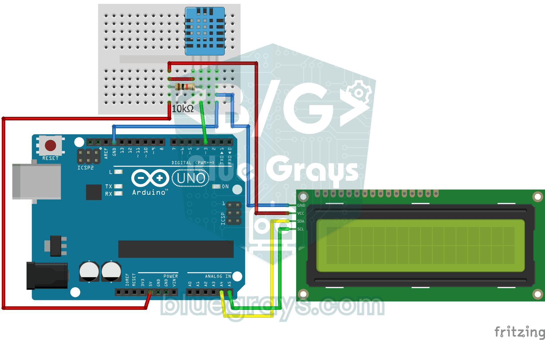
Temperature and Humidity with DHT11
How warm is your room, and is the air humid or dry? The DHT11 sensor measures temperature and humidity, and the Arduino writes the values on a two-line LCD screen, refreshing every couple of seconds.
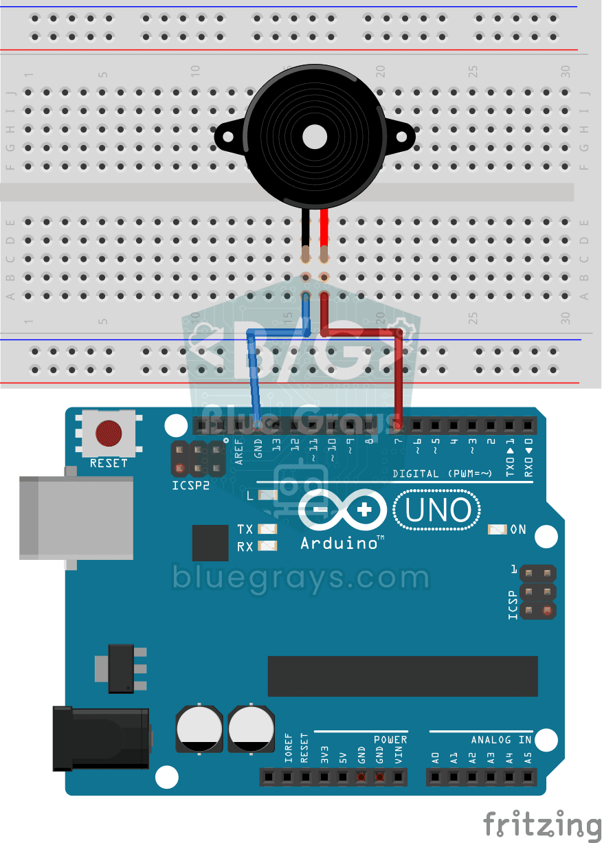
Using a Buzzer
Ever wondered how a doorbell or an alarm makes its sound? The Arduino makes a small buzzer beep at short intervals: beep, pause, beep, pause.
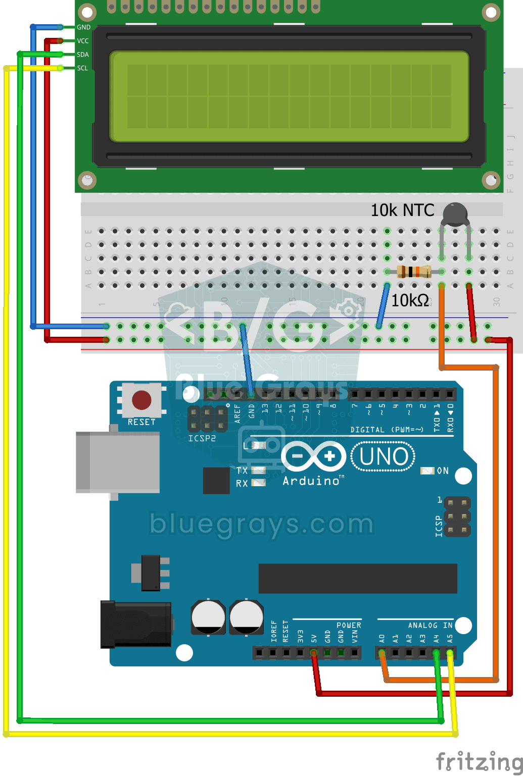
Temperature Measurement with NTC and 2x16 Lcd Display
Measure the temperature around you with a sensor that looks like a tiny bead. This part, called an NTC, lets electricity through more easily as it warms up; the Arduino reads that change, turns it…
Using LCD Screen with I2C
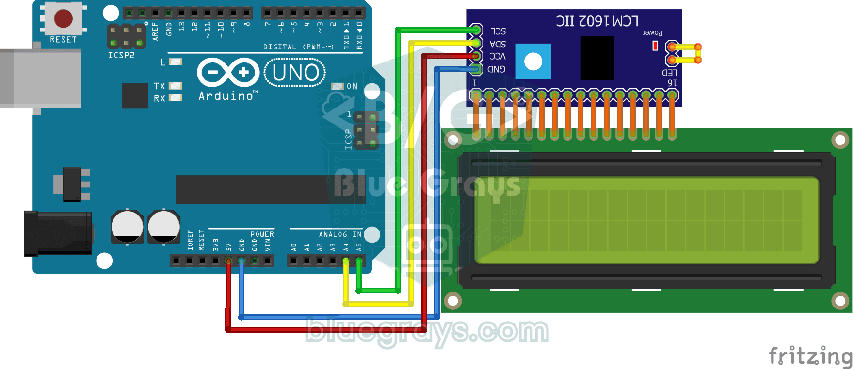
Give your Arduino its own screen and make it write its first message. The two-line LCD screen hooks up with just a few wires; a greeting appears on the top line, then a second message on the bottom…

ESP32 I2C LCD Display (16x2)
In this project we connect a 16x2 character LCD to the ESP32 over I2C and display text. With I2C, just 2 data pins (SDA and SCL) control the screen, instead of the 6+ pins a classic parallel connection wastes. The code prints a fixed message on the first line and a counter that goes up every second on the second. At startup an I2C scanner also prints the display's address to the Serial Monitor (usually 0x27 or 0x3F).

ESP32 DHT22 Temperature and Humidity (with LCD Display)
This project measures ambient temperature and humidity using a DHT22 sensor and displays the data in real time on a 16x2 I2C LCD. Data is read from the sensor using the one-wire protocol via the Adafruit DHT library. This project serves as the foundation for IoT weather stations, smart home automation, or environmental monitoring systems in greenhouses. Communication with the DHT22 is established via the ESP32's GPIO 4 pin.
ESP32 Temperature Data Logger (DHT22 + DS1307 RTC + microSD + OLED)
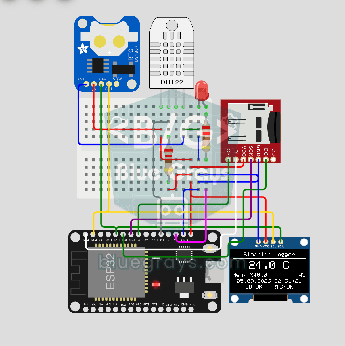
Build a timed temperature and humidity logger with the ESP32! A DHT22 sensor reads temperature and humidity once a minute, and each reading is saved to a microSD card in CSV format with a real-time stamp from the DS1307 RTC module. The OLED display shows the latest temperature, humidity, timestamp and total number of records live, in large text.
Using a Flame Sensor
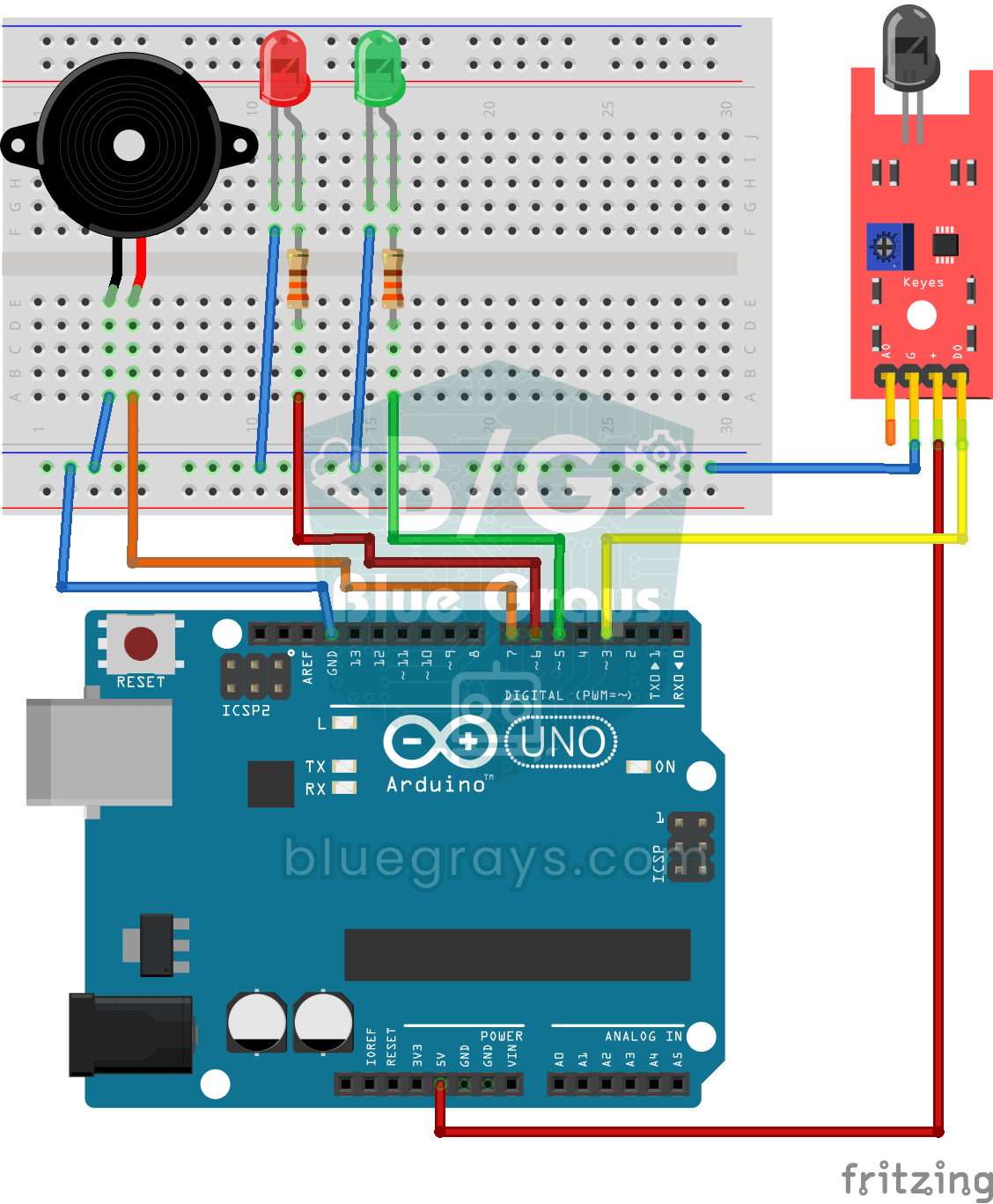
A little guard that spots fire before you do, in the kitchen or the workshop. The flame sensor picks up the invisible light that fire gives off; while all is well the green LED is on, and when it…