
Arduino Earthquake Alarm: MPU6050 Shake Detection Guide
Build an Arduino earthquake alarm with an MPU6050: calibration, setting the threshold, filtering door slams, buzzer and LED alerts, plus SW-420 and ESP32 versions.

An Arduino earthquake alarm is a simple but very instructive project: an accelerometer continuously measures the vibration of the surface it sits on, and when the shaking exceeds a certain strength and duration, it triggers a buzzer and an LED. In this guide you'll learn step by step how to calibrate the MPU6050 sensor, find the right threshold for your environment's noise, filter out false alarms such as a slamming door or someone walking past, and give an audible and visual warning. At the end you'll build the same logic with the cheap SW-420 vibration sensor, with an ESP32 version that sends notifications to your phone, and with a Raspberry Pi Pico running MicroPython.
Let's be clear from the start: this device is not a seismograph or an official earthquake early warning system. It can't predict an earthquake; it can only warn you once shaking has begun, and if you're lucky, a few seconds before the strongest waves arrive. Still, it's a great project for noticing a light tremor while you sleep, learning the concept of acceleration, and understanding signal processing and filtering, and it's a common choice for science fair presentations.
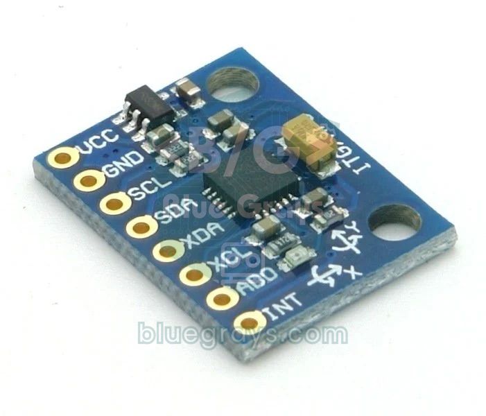
How does an earthquake alarm work?
When an earthquake happens, two main types of waves spread out from the source. The P waves (primary, compression waves) arrive first, travel through the crust at about 6 km per second and are usually felt more weakly. The S waves (secondary, shear waves) that follow travel at about 3.5 km/s and cause most of the damage. If you're 50 km from the epicentre, there's roughly a 6-second gap between the two waves; if you're right next to the epicentre, the gap is almost zero. Our alarm uses an accelerometer fixed to the floor to measure the small changes in acceleration these waves create. When the sensor is still, it sees only gravity (1 g ≈ 9.81 m/s²); once shaking starts, the values on the three axes oscillate around that resting position. In this article we'll call the size of this oscillation dynamic acceleration. For a detailed introduction to the sensor, see MPU6050 accelerometer and gyroscope.
| Feature | MPU6050 value |
|---|---|
| Sensor type | 3-axis accelerometer + 3-axis gyroscope (6-axis IMU) |
| Acceleration ranges | ±2 / ±4 / ±8 / ±16 g |
| Sensitivity (±2 g) | 16384 LSB/g (1 step ≈ 0.061 mg) |
| ADC resolution | 16 bits |
| Built-in low-pass filter (DLPF) | Selectable from about 5 to 260 Hz |
| Communication | I2C, up to 400 kHz |
| I2C address | 0x68 (AD0 = GND), 0x69 (AD0 = 3.3 V) |
| Supply (GY-521 module) | 3.3–5 V (3.3 V regulator on the board) |
| Current | About 4 mA |
Shaking intensity and acceleration: which value means what?
Seismologists usually express the strength of shaking at a location as peak ground acceleration (PGA). The table below shows the approximate relationship between ground acceleration and the intensity people feel, based on the Modified Mercalli scale. As you can see, even a shake people feel as light is in the 0.014–0.039 g range; in other words, we're dealing with tiny accelerations of 14–39 mg. Since one step of the MPU6050 on its ±2 g range is 0.061 mg, the resolution is more than enough; but because the sensor's own noise is a few mg at rest, we have to set the threshold above that noise. The values in the table are ground accelerations; shaking is amplified on the upper floors of a building, so use them only as a rough guide.
| Peak ground acceleration (g) | Mercalli intensity | Felt effect |
|---|---|---|
| < 0.0017 | I | Not felt |
| 0.0017 – 0.014 | II–III | Weak; felt in quiet conditions and on upper floors |
| 0.014 – 0.039 | IV | Light; most people notice it, windows rattle |
| 0.039 – 0.092 | V | Moderate; sleepers wake up, small objects fall over |
| 0.092 – 0.18 | VI | Strong; everyone feels it, plaster may crack |
| 0.18 – 0.34 | VII | Very strong; damage to weak structures |
Materials and wiring
- Board: Arduino Uno or Nano; an ESP32 for notifications, a Raspberry Pi Pico for MicroPython.
- MPU6050 (GY-521) module: The accelerometer that measures the shaking.
- Active buzzer: Small active buzzers draw about 20–30 mA; for a louder sound, drive the buzzer with an NPN transistor.
- Red LED and 220 Ω resistor: For the visual warning; you can check the resistor value with the LED resistor calculator.
- Push button: To silence the alarm (uses the internal pull-up, no extra resistor needed).
- Breadboard and jumper wires; optionally an SW-420 vibration sensor for the simple version.
| Connection | Arduino Uno | ESP32 | Raspberry Pi Pico |
|---|---|---|---|
| MPU6050 VCC | 5V | 3V3 | 3V3(OUT) |
| MPU6050 GND | GND | GND | GND |
| MPU6050 SCL | A5 | GPIO 22 | GP5 |
| MPU6050 SDA | A4 | GPIO 21 | GP4 |
| MPU6050 AD0 | GND (address 0x68) | GND (address 0x68) | GND (address 0x68) |
| Active buzzer (+) | D8 | GPIO 25 | GP15 |
| LED (with 220 Ω) | D7 | GPIO 26 | GP14 |
| Silence button (other end to GND) | D2 | GPIO 27 | GP13 |
| SW-420 DO (simple version) | D3 | - | - |
Calibration and setting the threshold
The purpose of calibration is to find the sensor's three-axis values at rest. A sensor is never perfectly level and every chip has a small offset; for example, the Z axis might read 0.97 g instead of 1.00 g and the X axis 0.02 g instead of 0. When the code starts, it takes 200 readings over about a second and stores their average as the baseline. For every later reading, this baseline is subtracted from each axis and the vector magnitude of the remainder is calculated: dynamic acceleration = √(dx² + dy² + dz²). The beauty of this method is that mounting the sensor flat, vertical or tilted doesn't change the result; gravity stays inside the baseline, so it drops out of the calculation automatically. The sensor's offset also drifts very slowly as the temperature changes; while the environment is quiet, the code updates the baseline by one thousandth on every reading to follow this drift too.
- Fix the sensor firmly in its permanent location, upload the code and don't touch the setup until the calibration message has passed.
- Open the Serial Plotter from the Tools menu (115200 baud). In a quiet environment you'll see the dynamic acceleration usually fluctuating between 0.002 and 0.008 g; this is your noise level.
- Note the highest value the noise reaches over a few minutes and choose a threshold 3–5 times that. The default 0.03 g in the code corresponds to light (IV) intensity.
- Tap the table lightly, close the door, walk around the room and watch how high and how long a peak each event creates on the plotter.
- To imitate a real shake, move the board the sensor is screwed to back and forth 1–3 times per second for a few seconds; the alarm should sound within about 1–2 seconds.
- If you get false alarms, raise THRESHOLD_G; if it detects shaking too late, lower SCORE_ALARM; change them in small steps and repeat the tests.
Filtering false alarms: door slams and footsteps
When a door slams, the sensor sees a large but very short (50–200 ms) impact of 0.1–0.5 g. An earthquake, on the other hand, produces smaller accelerations but oscillates for seconds, in the 1–10 Hz range. So the distinguishing feature isn't amplitude but duration. In the code we handle this with a score counter called a leaky bucket: 100 readings are taken per second, the score rises by 2 for every reading above the threshold, falls by 1 for every reading below it, and the alarm sounds when the score reaches 100. A 150 ms door slam produces at most 15 samples, that is 30 points, and drains away quickly. A shake that exceeds the threshold in about half the samples builds up a net 50 points per second and triggers the alarm in about 2 seconds. In addition, because the signal passes through the sensor's built-in 21 Hz low-pass filter, high-frequency vibrations such as fan, motor and compressor hum are largely suppressed. For more advanced filtering methods, take a look at sensor data filtering.
| False alarm source | Signal characteristic | Solution |
|---|---|---|
| Door slam | Single large impact lasting 50–200 ms | The score counter filters out short impacts; keep the sensor away from the door frame |
| Walking, jumping | Rhythmic 1–2 Hz, 0.01–0.05 g if close to the sensor | Mount the sensor on a load-bearing wall in a low-traffic corner and raise the threshold slightly |
| Washing machine, air conditioner | Long-lasting, constant-frequency vibration | Place the device in a room away from these machines and test the threshold while they run |
| Heavy vehicle passing | Low-amplitude vibration lasting a few seconds | Test day and night separately and set the threshold above the road vibration |
| Sensor shifting | Permanent offset, score keeps rising | Fix it with screws; if it has moved, reset the board and recalibrate |
Arduino earthquake alarm code (MPU6050 + buzzer + LED)
1#include <Wire.h>
2
3const int MPU_ADDR = 0x68;                  // AD0 = GND / AD0 = GND
4const int BUZZER_PIN = 8;                   // aktif buzzer / active buzzer
5const int LED_PIN = 7;                      // LED + 220 ohm
6const int BUTTON_PIN = 2;                   // susturma butonu / silence button
7
8const float THRESHOLD_G = 0.03;             // dinamik ivme eşiği (g) / dynamic acceleration threshold (g)
9const int SCORE_ALARM = 100;                // alarm puanı / alarm score
10const unsigned long SAMPLE_MS = 10;         // 100 Hz örnekleme / 100 Hz sampling
11const unsigned long ALARM_HOLD_MS = 30000;  // son sarsıntıdan sonra 30 s / 30 s after the last shake
12const bool DEBUG_PLOT = true;               // Seri Çizici çıktısı / Serial Plotter output
13
14float baseX, baseY, baseZ;                  // durağan taban değerleri / resting baseline
15int score = 0;
16bool alarmOn = false;
17float peakG = 0;
18unsigned long lastSample = 0;
19unsigned long lastShake = 0;
20
21void writeReg(uint8_t reg, uint8_t val) {
22  Wire.beginTransmission(MPU_ADDR);
23  Wire.write(reg);
24  Wire.write(val);
25  Wire.endTransmission();
26}
27
28void readAccel(float &ax, float &ay, float &az) {
29  Wire.beginTransmission(MPU_ADDR);
30  Wire.write(0x3B);                         // ACCEL_XOUT_H
31  Wire.endTransmission(false);
32  Wire.requestFrom(MPU_ADDR, 6);
33  uint8_t b[6];
34  for (int i = 0; i < 6; i++) b[i] = Wire.read();
35  ax = (int16_t)((b[0] << 8) | b[1]) / 16384.0;   // ±2 g: 16384 LSB/g
36  ay = (int16_t)((b[2] << 8) | b[3]) / 16384.0;
37  az = (int16_t)((b[4] << 8) | b[5]) / 16384.0;
38}
39
40void calibrate() {
41  float sx = 0, sy = 0, sz = 0;
42  for (int i = 0; i < 200; i++) {
43    float ax, ay, az;
44    readAccel(ax, ay, az);
45    sx += ax; sy += ay; sz += az;
46    delay(5);
47  }
48  baseX = sx / 200; baseY = sy / 200; baseZ = sz / 200;
49}
50
51void setup() {
52  Serial.begin(115200);
53  pinMode(BUZZER_PIN, OUTPUT);
54  pinMode(LED_PIN, OUTPUT);
55  pinMode(BUTTON_PIN, INPUT_PULLUP);
56  Wire.begin();
57  writeReg(0x6B, 0x00);                     // uyku modundan çık / wake up
58  writeReg(0x1C, 0x00);                     // ±2 g aralığı / ±2 g range
59  writeReg(0x1A, 0x04);                     // DLPF ~21 Hz
60  delay(100);
61  Serial.println(F("Kalibrasyon, dokunma / Calibrating, do not touch"));
62  calibrate();
63  lastSample = millis();
64}
65
66void loop() {
67  if (millis() - lastSample >= SAMPLE_MS) {
68    lastSample += SAMPLE_MS;
69    float ax, ay, az;
70    readAccel(ax, ay, az);
71    float dx = ax - baseX, dy = ay - baseY, dz = az - baseZ;
72    float dyn = sqrt(dx * dx + dy * dy + dz * dz);   // dinamik ivme (g) / dynamic acceleration (g)
73    if (DEBUG_PLOT) Serial.println(dyn, 4);
74
75    if (dyn > THRESHOLD_G) {
76      score = min(score + 2, 200);          // eşik üstü: +2 / above threshold: +2
77      if (dyn > peakG) peakG = dyn;
78    } else if (score > 0) {
79      score--;                              // eşik altı: -1 / below threshold: -1
80    }
81
82    if (score == 0 && !alarmOn) {           // sakin: tabanı yavaşça izle / quiet: track baseline slowly
83      baseX += (ax - baseX) * 0.001;
84      baseY += (ay - baseY) * 0.001;
85      baseZ += (az - baseZ) * 0.001;
86      peakG = 0;
87    }
88
89    if (score >= SCORE_ALARM) {
90      if (!alarmOn && !DEBUG_PLOT) {
91        Serial.print(F("SARSINTI! Tepe / Peak: "));
92        Serial.print(peakG, 3);
93        Serial.println(F(" g"));
94      }
95      alarmOn = true;
96      lastShake = millis();
97    }
98  }
99
100  if (alarmOn && (millis() - lastShake > ALARM_HOLD_MS || digitalRead(BUTTON_PIN) == LOW)) {
101    alarmOn = false;                        // süre doldu ya da susturuldu / timeout or silenced
102    score = 0;
103  }
104
105  bool on = alarmOn && ((millis() / 250) % 2);   // 2 Hz yanıp sönme / 2 Hz blinking
106  digitalWrite(LED_PIN, on);
107  digitalWrite(BUZZER_PIN, on);
108}| Code part | What it does |
|---|---|
| writeReg(0x6B, 0x00) | The MPU6050 starts in sleep mode; this command wakes the sensor |
| writeReg(0x1C, 0x00) | Sets the acceleration range to ±2 g; in this range 1 g = 16384 counts |
| writeReg(0x1A, 0x04) | Sets the built-in low-pass filter to about 21 Hz |
| calibrate() | Finds the resting baseline values by averaging 200 readings |
| dyn | Vector magnitude of the deviation from the baseline, i.e. dynamic acceleration (g) |
| score | +2 for every sample above the threshold, -1 for every sample below; the alarm sounds at 100 |
| ALARM_HOLD_MS | The alarm lasts 30 s after the last shake; the button silences it early |
| millis() timing | Gives steady 100 Hz sampling without using delay |
Simple earthquake alarm with the SW-420
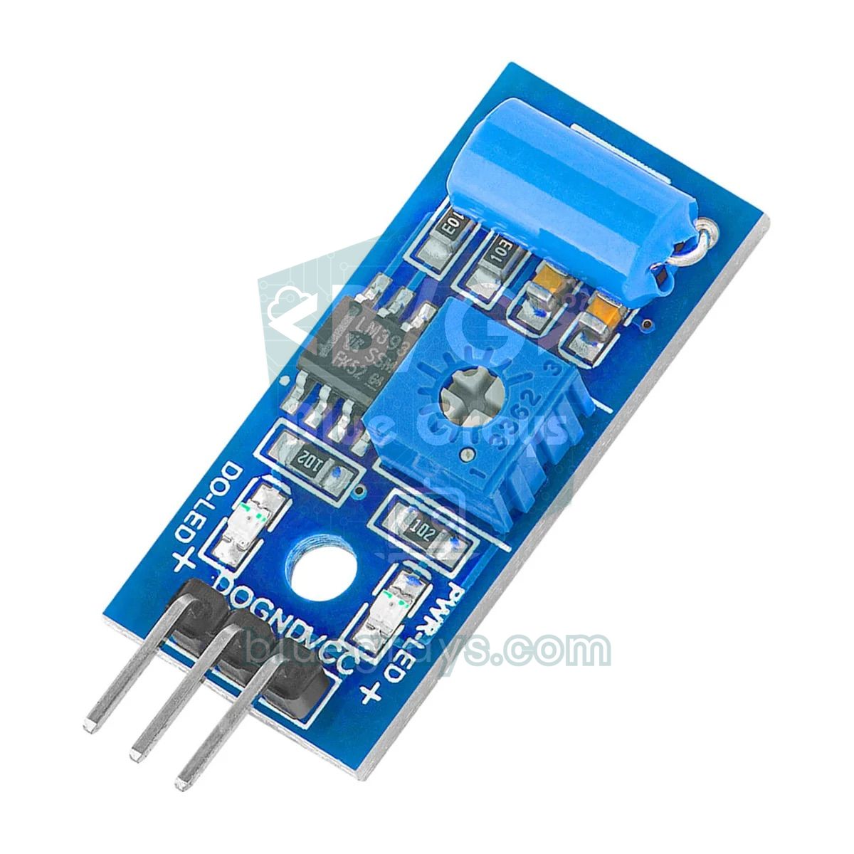
The SW-420 module consists of a simple vibration switch with a spring contact inside and an LM393 comparator. At rest the contact is closed and the DO output stays LOW; as vibration opens and closes the contact, the DO pin produces HIGH pulses. The potentiometer on the module adjusts the sensitivity. It doesn't measure acceleration, it only tells you whether there is vibration or not; so it can't tell strength apart, but it's very cheap and the code is simple. The code below counts the pulses with an interrupt; if 15 or more pulses per second arrive for 2 seconds in a row, it starts a 20-second alarm. This way a single door slam is filtered out here too. For module details, see SW-420 vibration sensor.
1const byte SENSOR_PIN = 3;                  // SW-420 DO (kesme pini / interrupt pin)
2const byte BUZZER_PIN = 8;
3const byte LED_PIN = 7;
4const unsigned int PULSE_LIMIT = 15;        // saniyedeki darbe sınırı / pulses per second limit
5
6volatile unsigned int pulses = 0;
7unsigned long lastCheck = 0;
8unsigned long alarmUntil = 0;
9byte busySeconds = 0;
10
11void onPulse() {
12  pulses++;                                 // her titreşim darbesini say / count each vibration pulse
13}
14
15void setup() {
16  Serial.begin(115200);
17  pinMode(SENSOR_PIN, INPUT);
18  pinMode(BUZZER_PIN, OUTPUT);
19  pinMode(LED_PIN, OUTPUT);
20  attachInterrupt(digitalPinToInterrupt(SENSOR_PIN), onPulse, RISING);
21}
22
23void loop() {
24  if (millis() - lastCheck >= 1000) {       // her saniye değerlendir / evaluate every second
25    lastCheck = millis();
26    noInterrupts();
27    unsigned int n = pulses;
28    pulses = 0;
29    interrupts();
30    Serial.println(n);
31    if (n >= PULSE_LIMIT) busySeconds++;
32    else busySeconds = 0;
33    if (busySeconds >= 2) alarmUntil = millis() + 20000;   // 2 s sürekli titreşim / 2 s continuous vibration
34  }
35
36  bool alarm = (long)(alarmUntil - millis()) > 0;
37  bool on = alarm && ((millis() / 250) % 2);
38  digitalWrite(BUZZER_PIN, on);
39  digitalWrite(LED_PIN, on);
40}
ESP32 earthquake alarm with phone notifications
While running the same detection logic, the ESP32 can also send a Telegram message to your phone over Wi-Fi. To do this, install the UniversalTelegramBot library and its dependency ArduinoJson from the Library Manager, create a bot with BotFather and put the token and your own chat ID in the code; all the steps are in ESP32 Telegram bot. There's an important design decision here: a Wi-Fi connection is not a precondition for the alarm. Power or internet may go down during an earthquake; so the buzzer and LED always work locally, and the message is sent only if there's a connection, once per event. Backing the device up with an 18650 battery, a TP4056 charging module and a suitable voltage regulator lets it keep working during a power cut.
1#include <Wire.h>
2#include <WiFi.h>
3#include <WiFiClientSecure.h>
4#include <UniversalTelegramBot.h>
5
6const char* WIFI_SSID = "WIFI_ADI";
7const char* WIFI_PASS = "WIFI_SIFRESI";
8#define BOT_TOKEN "123456789:BOT_TOKENIN"     // BotFather'dan / from BotFather
9#define CHAT_ID "123456789"                   // kendi chat ID'n / your chat ID
10
11const int MPU_ADDR = 0x68;
12const int BUZZER_PIN = 25;
13const int LED_PIN = 26;
14const int BUTTON_PIN = 27;
15const float THRESHOLD_G = 0.03;
16const int SCORE_ALARM = 100;
17const unsigned long ALARM_HOLD_MS = 30000;
18
19WiFiClientSecure client;
20UniversalTelegramBot bot(BOT_TOKEN, client);
21
22float baseX, baseY, baseZ;
23int score = 0;
24bool alarmOn = false;
25bool messageSent = false;
26float peakG = 0;
27unsigned long lastSample = 0, lastShake = 0;
28
29void writeReg(uint8_t reg, uint8_t val) {
30  Wire.beginTransmission(MPU_ADDR);
31  Wire.write(reg);
32  Wire.write(val);
33  Wire.endTransmission();
34}
35
36void readAccel(float &ax, float &ay, float &az) {
37  Wire.beginTransmission(MPU_ADDR);
38  Wire.write(0x3B);
39  Wire.endTransmission(false);
40  Wire.requestFrom(MPU_ADDR, 6);
41  uint8_t b[6];
42  for (int i = 0; i < 6; i++) b[i] = Wire.read();
43  ax = (int16_t)((b[0] << 8) | b[1]) / 16384.0;
44  ay = (int16_t)((b[2] << 8) | b[3]) / 16384.0;
45  az = (int16_t)((b[4] << 8) | b[5]) / 16384.0;
46}
47
48void setup() {
49  Serial.begin(115200);
50  pinMode(BUZZER_PIN, OUTPUT);
51  pinMode(LED_PIN, OUTPUT);
52  pinMode(BUTTON_PIN, INPUT_PULLUP);
53  Wire.begin(21, 22);                         // SDA, SCL
54  writeReg(0x6B, 0x00);                       // uyandır / wake up
55  writeReg(0x1C, 0x00);                       // ±2 g
56  writeReg(0x1A, 0x04);                       // DLPF ~21 Hz
57  delay(100);
58  float sx = 0, sy = 0, sz = 0;               // kalibrasyon / calibration
59  for (int i = 0; i < 200; i++) {
60    float ax, ay, az;
61    readAccel(ax, ay, az);
62    sx += ax; sy += ay; sz += az;
63    delay(5);
64  }
65  baseX = sx / 200; baseY = sy / 200; baseZ = sz / 200;
66  client.setCACert(TELEGRAM_CERTIFICATE_ROOT);
67  WiFi.begin(WIFI_SSID, WIFI_PASS);           // bağlanmayı beklemez / does not block
68  lastSample = millis();
69}
70
71void loop() {
72  if (millis() - lastSample >= 10) {          // 100 Hz örnekleme / 100 Hz sampling
73    lastSample += 10;
74    float ax, ay, az;
75    readAccel(ax, ay, az);
76    float dx = ax - baseX, dy = ay - baseY, dz = az - baseZ;
77    float dyn = sqrt(dx * dx + dy * dy + dz * dz);
78    if (dyn > THRESHOLD_G) {
79      score = min(score + 2, 200);
80      if (dyn > peakG) peakG = dyn;
81    } else if (score > 0) {
82      score--;
83    }
84    if (score == 0 && !alarmOn) {
85      baseX += (ax - baseX) * 0.001;
86      baseY += (ay - baseY) * 0.001;
87      baseZ += (az - baseZ) * 0.001;
88      peakG = 0;
89    }
90    if (score >= SCORE_ALARM) {
91      alarmOn = true;
92      lastShake = millis();
93    }
94  }
95
96  if (alarmOn && !messageSent && WiFi.status() == WL_CONNECTED) {
97    digitalWrite(LED_PIN, HIGH);              // gönderirken de uyar / keep warning while sending
98    digitalWrite(BUZZER_PIN, HIGH);
99    String msg = String("Sarsinti algilandi! Tepe ivme: ") + String(peakG, 3) + " g";
100    bot.sendMessage(CHAT_ID, msg, "");
101    messageSent = true;                       // olay başına bir mesaj / one message per event
102    lastSample = millis();                    // kaçan örnekleri atla / skip missed samples
103  }
104
105  if (alarmOn && (millis() - lastShake > ALARM_HOLD_MS || digitalRead(BUTTON_PIN) == LOW)) {
106    alarmOn = false;
107    messageSent = false;
108    score = 0;
109  }
110
111  bool on = alarmOn && ((millis() / 250) % 2);
112  digitalWrite(LED_PIN, on);
113  digitalWrite(BUZZER_PIN, on);
114}
MicroPython version with the Raspberry Pi Pico
No extra library is needed on the Pico; MicroPython's built-in I2C class and the struct module are enough to read the MPU6050's raw data. The logic is identical to the Arduino code: calibration, dynamic acceleration, the score counter and a 30-second alarm. Because the Pico's pins output 3.3 V, small 5 V active buzzers sound quieter; if you want more volume, drive the buzzer from 5 V (VBUS) with an NPN transistor. If you're new to MicroPython, first read MicroPython basics.
1from machine import Pin, I2C
2import struct, time, math
3
4i2c = I2C(0, sda=Pin(4), scl=Pin(5), freq=400000)
5MPU = 0x68
6buzzer = Pin(15, Pin.OUT)
7led = Pin(14, Pin.OUT)
8button = Pin(13, Pin.IN, Pin.PULL_UP)        # susturma butonu / silence button
9
10i2c.writeto_mem(MPU, 0x6B, b'\x00')          # uyandır / wake up
11i2c.writeto_mem(MPU, 0x1C, b'\x00')          # ±2 g
12i2c.writeto_mem(MPU, 0x1A, b'\x04')          # DLPF ~21 Hz
13time.sleep_ms(100)
14
15def read_accel():
16    x, y, z = struct.unpack('>hhh', i2c.readfrom_mem(MPU, 0x3B, 6))
17    return x / 16384, y / 16384, z / 16384
18
19print("Kalibrasyon / Calibrating...")
20sx = sy = sz = 0
21for _ in range(200):
22    ax, ay, az = read_accel()
23    sx += ax; sy += ay; sz += az
24    time.sleep_ms(5)
25bx, by, bz = sx / 200, sy / 200, sz / 200
26
27THRESHOLD = 0.03                              # eşik (g) / threshold (g)
28score = 0
29alarm = False
30last_shake = 0
31
32while True:
33    t0 = time.ticks_ms()
34    ax, ay, az = read_accel()
35    dyn = math.sqrt((ax - bx) ** 2 + (ay - by) ** 2 + (az - bz) ** 2)
36    if dyn > THRESHOLD:
37        score = min(score + 2, 200)
38    elif score > 0:
39        score -= 1
40    if score == 0 and not alarm:              # tabanı yavaşça izle / track baseline slowly
41        bx += (ax - bx) * 0.001
42        by += (ay - by) * 0.001
43        bz += (az - bz) * 0.001
44    if score >= 100:
45        alarm = True
46        last_shake = time.ticks_ms()
47    if alarm and (time.ticks_diff(time.ticks_ms(), last_shake) > 30000 or button.value() == 0):
48        alarm = False
49        score = 0
50    on = alarm and (time.ticks_ms() // 250) % 2 == 1
51    buzzer.value(on)
52    led.value(on)
53    time.sleep_ms(max(0, 10 - time.ticks_diff(time.ticks_ms(), t0)))   # ~100 Hz
Project ideas to improve your earthquake alarm
- Mini seismometer with a screen: Draw the dynamic acceleration as a scrolling graph on an OLED display and show the peak value of the last event and its estimated Mercalli intensity.
- Event logger: Write the time and peak acceleration of every shake to an SD card module; add date and time with an RTC.
- Emergency lighting: Automatically turn on the hallway light with a relay module when shaking is detected.
- Integrated home security: Add earthquake detection to the same alarm system as gas, smoke and motion sensors.
- Multiple notifications: Send a WhatsApp message with the ESP32 instead of, or in addition to, Telegram.
- Science project: Place sensors on different floors and measure how vibration grows with height; for ideas, see TÜBİTAK Arduino project ideas.
Common mistakes and how to fix them
| Symptom | Likely cause | Fix |
|---|---|---|
| Values are always 0 or never change | Sensor is asleep or the I2C wiring is wrong | Check the 0x6B write, verify the SDA/SCL pins, find the address with an I2C scanner |
| Alarm sounds right after power-up | Sensor moved during calibration | Don't touch the circuit during calibration, reset the board |
| Alarm never stops | Buzzer vibration is reaching the sensor or the sensor has shifted | Mount the buzzer on a surface separate from the sensor, fix the sensor and recalibrate |
| No reaction to light shaking | THRESHOLD_G or SCORE_ALARM is too high | Measure the noise on the Serial Plotter and lower the threshold step by step |
| No message from the ESP32 | Token or chat ID is wrong, Wi-Fi isn't connected | Check the details, print WiFi.status() in the Serial Monitor |
| Random freezes | Long, loose I2C wires | Keep the wires under 30 cm and check the breadboard contacts |
| Buzzer is too quiet | 3.3 V pin or insufficient current | Drive the buzzer from 5 V with an NPN transistor |
You now have an earthquake alarm that measures acceleration, calibrates itself, filters out short impacts and gives an audible and visual warning on a real shake; and you can build the same logic on Arduino, ESP32 and Pico. To reinforce buzzer, LED and alarm logic, check out the buzzer, police light, laser security system and ESP32 motion alarm projects in the BlueGrays app, with step-by-step circuit diagrams and ready-made code.
Frequently asked questions
Can you build an earthquake alarm with Arduino, and does it really work?
Yes, with an accelerometer like the MPU6050 you can build an alarm that detects shaking of noticeable strength and warns you with a buzzer and LED. It helps you notice a light tremor while you sleep and is an instructive project. However, it isn't a seismograph or an official early warning system, so you shouldn't base safety decisions on it.
Does an earthquake alarm warn you before the earthquake?
No, no device can predict an earthquake in advance. A local sensor only sounds once shaking has started. If you're far from the epicentre, it can catch the weak P waves and warn you a few seconds before the strong S waves; if you're close to the epicentre, that time is almost zero.
Which is better for an earthquake alarm, the MPU6050 or the SW-420?
Because the MPU6050 measures acceleration numerically, you can fine-tune the threshold and evaluate the strength and duration of the shaking, which makes filtering false alarms much easier. The SW-420 only tells you whether there is vibration or not; it's cheap and simple but can't tell strength apart. For a serious project, choose the MPU6050.
Where in the house should the earthquake sensor be mounted?
Screw the sensor firmly to a load-bearing wall or the floor, not to furniture. A corner away from doors, the washing machine and busy walking routes, ideally on a lower floor close to the ground, gives the fewest false alarms. Also mount the buzzer on a separate spot, not on the same surface as the sensor.
Can Arduino measure earthquake magnitude?
No. Earthquake magnitude expresses the energy released at the source and is calculated from the data of many stations. Arduino only measures the acceleration at its own location; this value varies greatly with distance to the epicentre, the ground and the floor. You can only roughly convert the peak acceleration you measure into felt intensity (Mercalli).
What should the threshold value be for an earthquake alarm, in g?
First measure your environment's noise on the Serial Plotter; the MPU6050 usually fluctuates between 0.002 and 0.008 g in a quiet environment. You can choose a threshold 3–5 times that noise, typically 0.02–0.04 g; this range corresponds to intensity IV, which people feel as light. Then fine-tune with door and footstep tests.
Projects to build after reading this
See all projects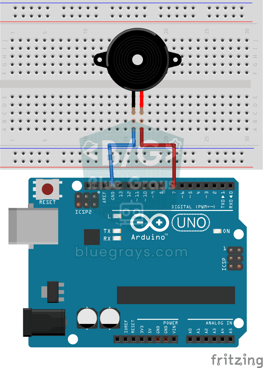
Using a Buzzer
Ever wondered how a doorbell or an alarm makes its sound? The Arduino makes a small buzzer beep at short intervals: beep, pause, beep, pause.

LED Blink
The very first hello of electronics: switching a single LED on and off. The Arduino turns the LED on and off at short intervals, so the light blinks quickly.

LED Police Lights
Just like the lights on a police car: the red LED flashes three times in quick succession, then the blue LED flashes three times, and the pattern keeps repeating without a break.
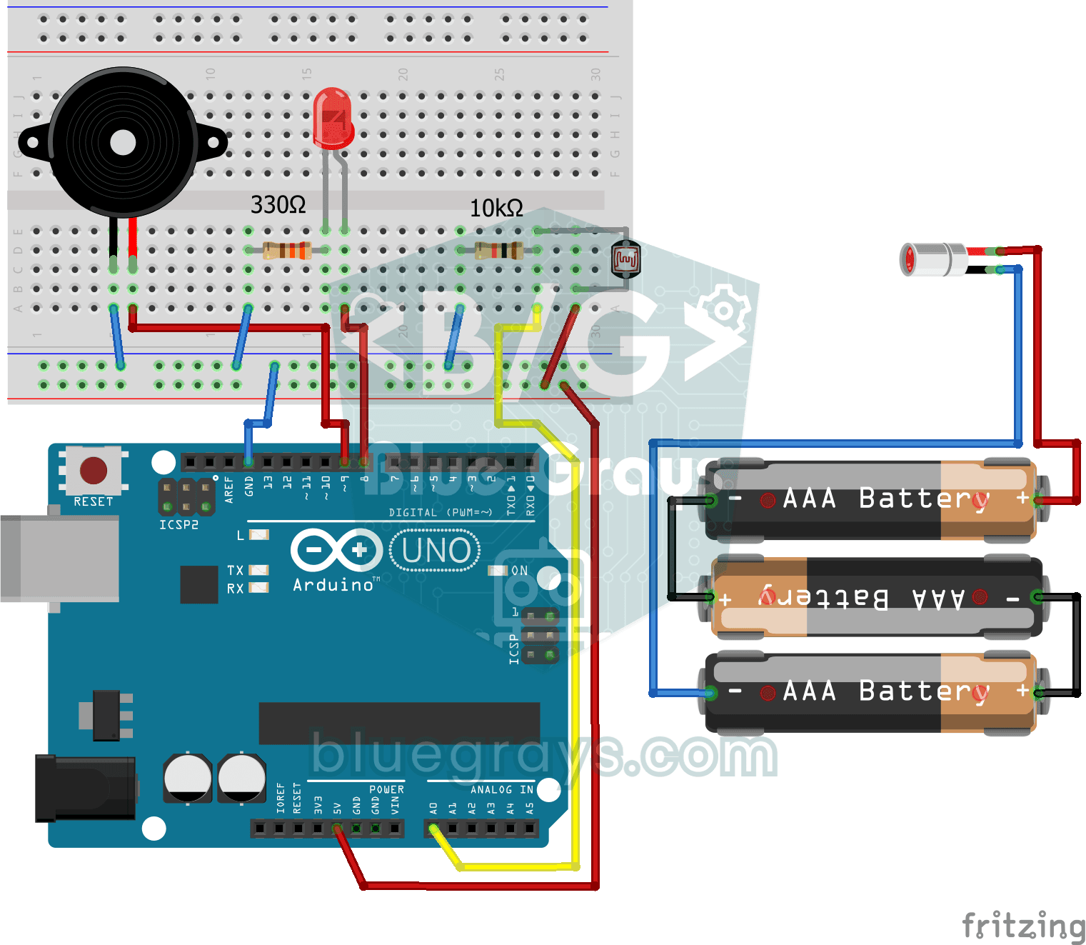
Laser Warning System
You set up an invisible beam fence, just like in the movies. A laser shines onto a light sensor on the other side; the moment someone walks through and breaks the beam, the LED lights up and the…
Flame and Gas Sensor Alarm
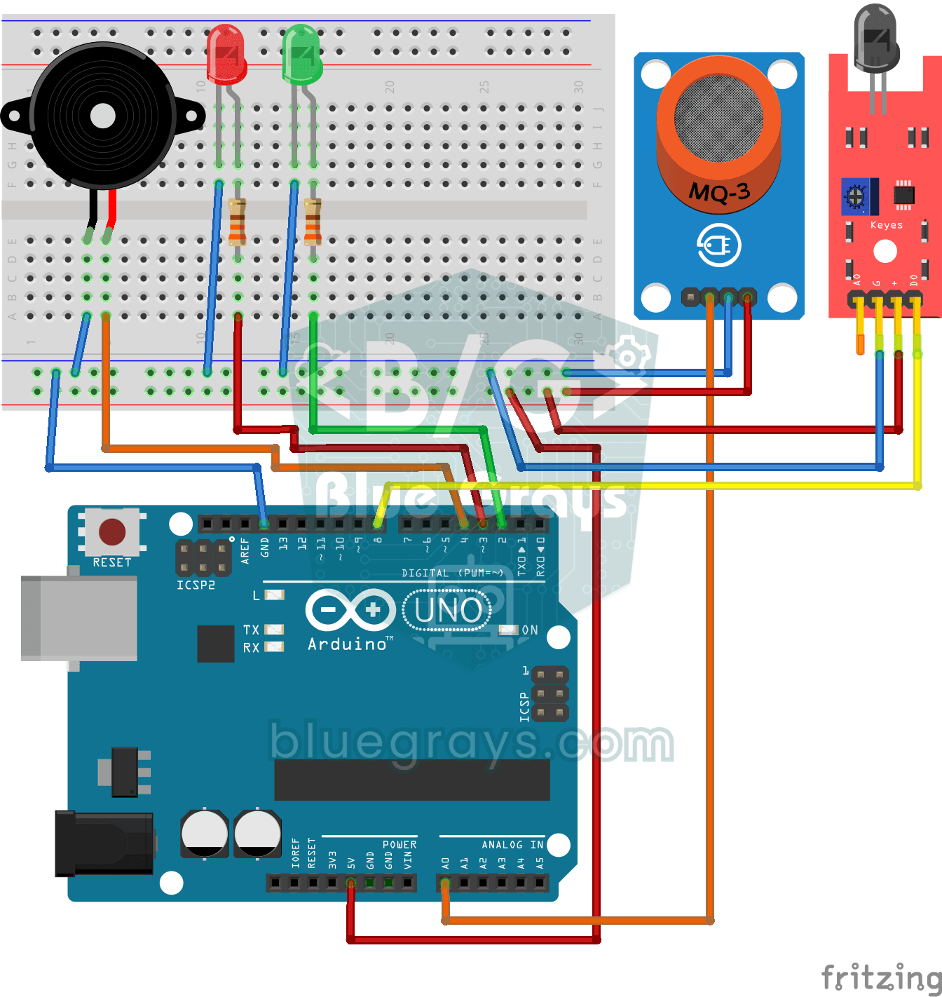
A little guard that warns you right away when gas leaks or a flame appears somewhere.

ESP32 MQ-2 Gas/Smoke Detector Alarm
In this project, combustible gas (LPG, methane, propane) and smoke detection is performed using an MQ-2 gas sensor module, and a siren-like alarm is played through a passive buzzer upon detection. The sensor's digital threshold output (DO) is connected to GPIO 4 on the ESP32; when gas or smoke exceeds the threshold, DO goes LOW and the alarm is triggered. Sensitivity is adjusted via the module's potentiometer. The passive buzzer is driven using tone() to produce a two-frequency siren effect.
ESP32 Motion Alarm System (PIR + Buzzer + LED + Telegram)
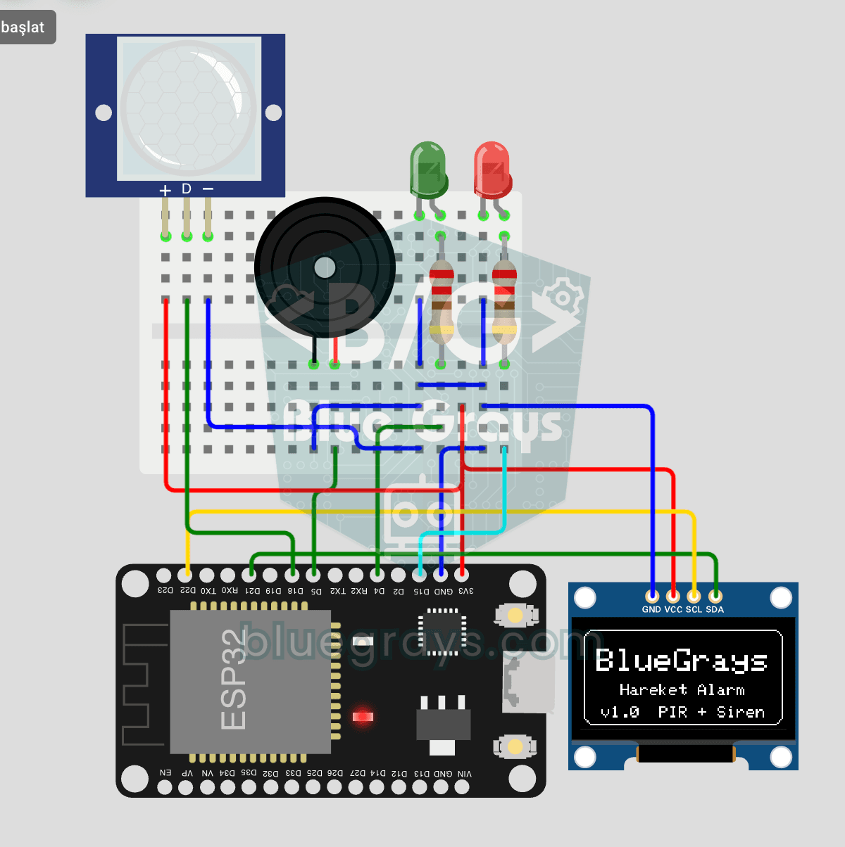
A smart security alarm: when the PIR sensor detects motion, it sounds the buzzer, lights the LED and sends the owner an instant Telegram notification. A 30-second cooldown limits how often the alarm repeats; it does not filter out the PIR sensor's false detections. Use it at home, in a garage, a storeroom or a study.