
Arduino LED Cube: How to Build a 3x3x3 and 4x4x4 Cube with Code
Build an Arduino LED cube: soldering jig, 3x3x3 and 4x4x4 assembly, transistor layer drivers, resistor maths, 74HC595 expansion and array animation code.
An LED cube is one of the most eye-catching light projects you can build with Arduino: LEDs arranged in a three-dimensional grid light up layer by layer to draw spinning planes, falling raindrops and cubes that grow and shrink in mid-air. The best way to start an Arduino LED cube is with a 3x3x3 (27 LEDs) or 4x4x4 (64 LEDs) size; at these sizes the pins of an Arduino Uno, a few transistors and some patient soldering are all you need. The trick is not to give every LED its own pin but to use a method called layer-column multiplexing: you control 27 LEDs with 12 pins, and 64 LEDs with just 7 pins thanks to two 74HC595 chips.
In this guide you'll learn how an LED cube works, how to make a soldering jig, how to join the layers step by step, why the layers must be driven by transistors and how the resistor values are calculated. After that you'll find Arduino code that plays array-based animations on a 3x3x3 cube, how to scale up to a 4x4x4 cube with the 74HC595, ESP32 and Raspberry Pi Pico (MicroPython) versions, a WS2812B alternative for a colour cube, and fixes for the most common assembly mistakes such as a reversed LED or a cold solder joint.
What is an LED cube and how does it work?
An LED cube is made by stacking horizontal layers of evenly spaced LEDs. In each layer the cathode (−) legs of all the LEDs are soldered together, so every layer has a single common cathode line. The anode (+) legs of LEDs sitting above one another are soldered together vertically and form the columns. A 3x3x3 cube has 3 layers and 9 columns, and a 4x4x4 cube has 4 layers and 16 columns. Every LED sits exactly at the crossing of one layer and one column: to light an LED you put a positive voltage on its column and connect its layer to GND.
You can describe every LED in the cube with three coordinates: x (left to right), y (front to back) and z (bottom to top). In the code in this article the column number is calculated as c = y × 3 + x (c = y × 4 + x on a 4x4x4), and z is the layer number. Just like a pixel on a screen, a single point of light in the cube is called a voxel (volume pixel). Making an animation really means deciding which voxels are lit at which moment.
How does layer-column multiplexing work?
If you switch on more than one layer at a time, the positive voltage you put on a column lights an LED in every active layer of that column, so you can't draw the pattern you want. That's why the cube is scanned layer by layer: the Arduino first switches off all layers, writes the column pattern of the first layer to the pins, turns on only that layer for a few milliseconds, then switches it off and moves on to the second layer. When this loop repeats more than a hundred times per second, your eye holds the light for a moment (persistence of vision), so you see all the layers lit at the same time.
Working out the scan rate is easy: refresh rate = 1 / (number of layers × layer time). If you keep each layer of a 3x3x3 cube on for 3 ms, one pass takes 9 ms and the cube refreshes about 110 times per second. On a 4x4x4 with 2 ms per layer, a pass takes 8 ms and the rate is 125 Hz. Below 50–60 Hz the eye notices flicker; above 100 Hz it looks completely steady to the eye and shows less banding on a phone camera. The price is brightness: because each layer is lit only 1/3 of the time (1/4 on a 4x4x4), an LED's average current drops to that fraction of its instantaneous current.
| Cube | LEDs | Columns + layers | Pins, direct drive | Pins with 74HC595 | Pins without multiplexing |
|---|---|---|---|---|---|
| 3x3x3 | 27 | 9 + 3 | 12 | 3 + 3 = 6 | 27 |
| 4x4x4 | 64 | 16 + 4 | 20 | 3 + 4 = 7 | 64 |
| 5x5x5 | 125 | 25 + 5 | 30 | 3 + 5 = 8 | 125 |
| 8x8x8 | 512 | 64 + 8 | 72 | 3 + 8 = 11 | 512 |
Parts list
| Part | 3x3x3 cube | 4x4x4 cube (with 74HC595) |
|---|---|---|
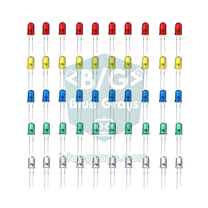
| 5 mm LED (single colour, diffused if possible) | 27 + 3 spares | 64 + 6 spares |
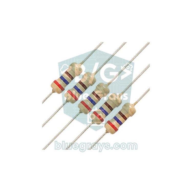
| Column resistor | 9 × 220 Ω | 16 × 330 Ω (blue, white) or 470 Ω (red, yellow) |
| NPN transistor (layer) | 3 × 2N2222A or BC337 | 4 × 2N2222A or BC337 |
| Base resistor | 3 × 470 Ω | 4 × 470 Ω |
| Shift register | Not needed | 2 × 74HC595 (74HCT595 for ESP32 and Pico) + 100 nF each |
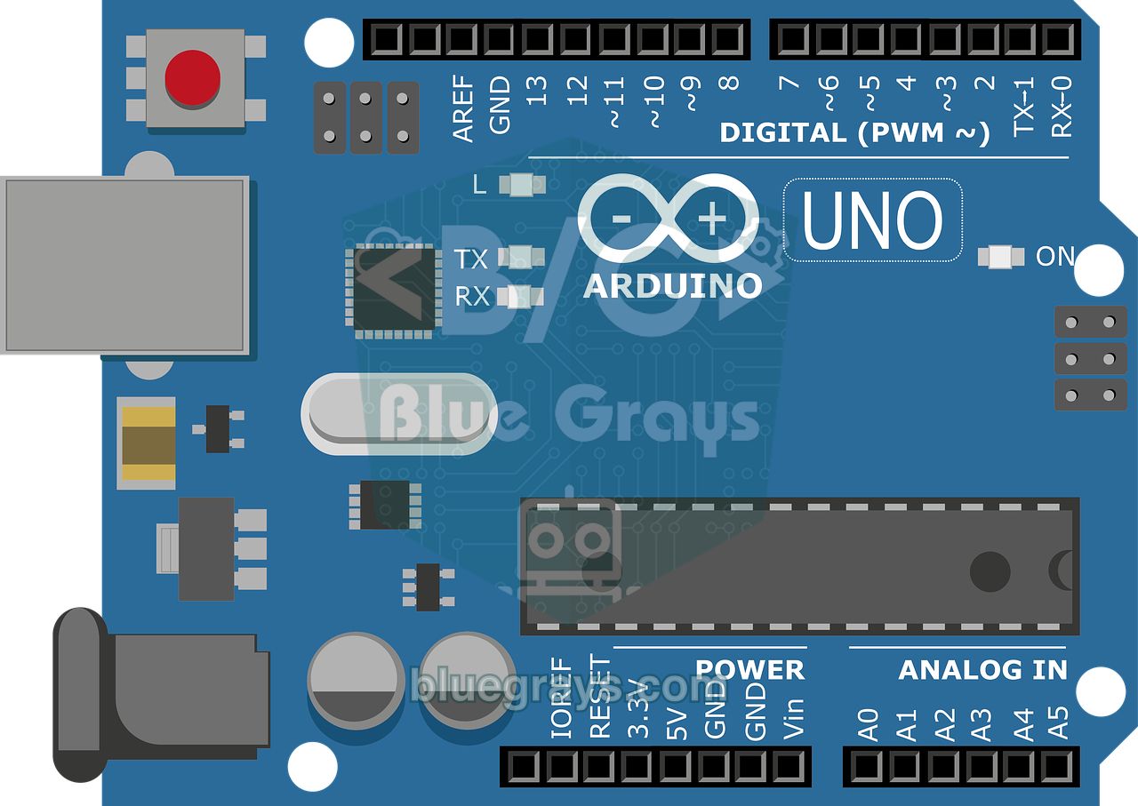
| Controller board | Arduino Uno or Nano | Arduino Uno, Nano, ESP32 or Pico |
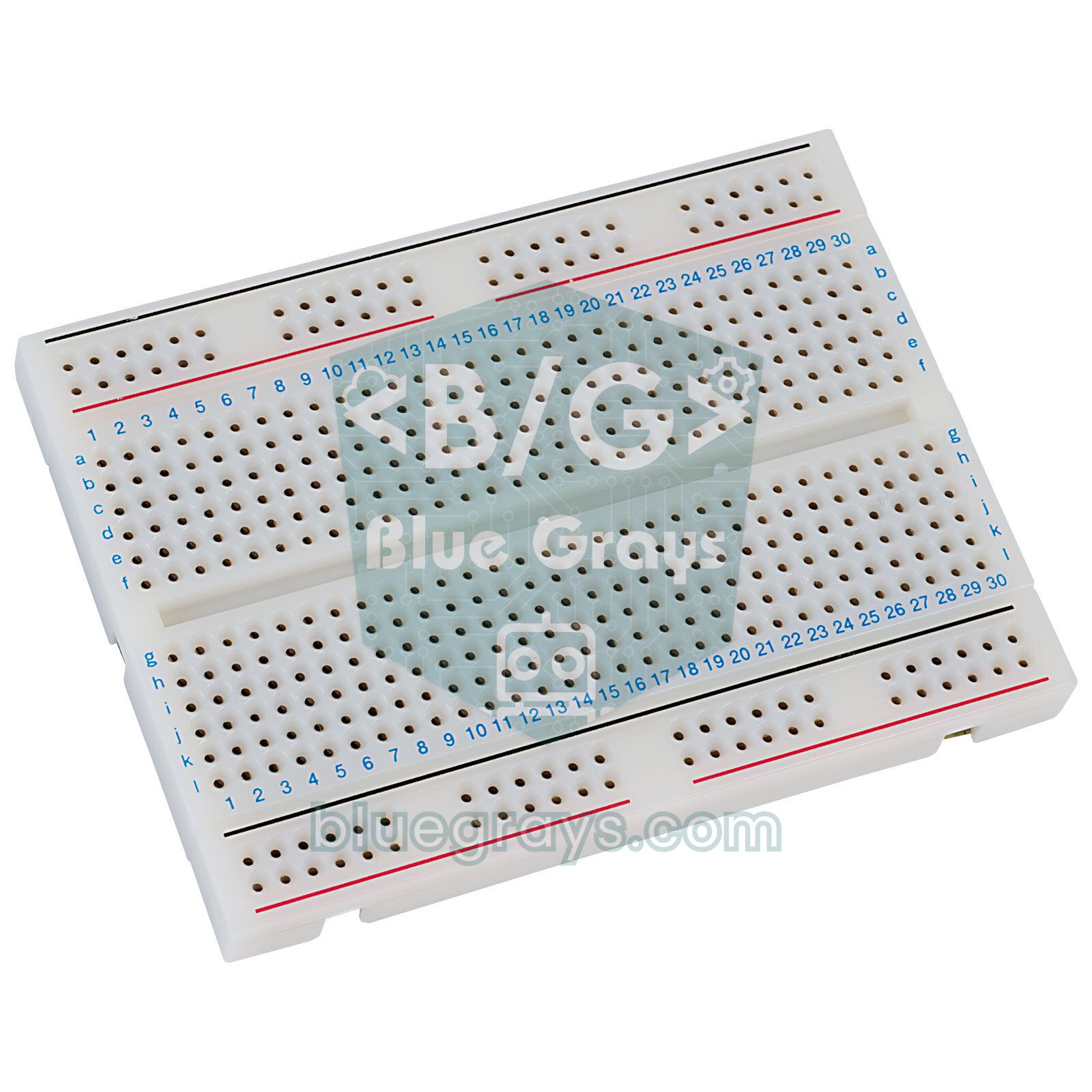
| Assembly | Perfboard, thin solid-core wire | Perfboard, 0.5–0.8 mm tinned copper wire |
| Tools | Soldering iron, solder, side cutters, pliers, 5 mm drill bit | Same tools + spacers of equal height |
Making a soldering jig
The secret of a neat cube is the jig. If you solder the LEDs while holding them by hand, the spacing drifts, the layers end up crooked and the cube looks skewed. A jig is a piece of wood with evenly spaced holes in which the LEDs sit upside down, dome facing down. The spacing is set by the length of the cathode leg: on most 5 mm LEDs the short leg is around 25 mm, but measure your own LEDs with a ruler. When you bend the leg 90° about 2–3 mm from the body, the remaining horizontal part should overlap the neighbouring LED's leg by 2–3 mm, which is why a spacing of 20 mm is a good starting point.
- Draw a 3x3 (or 4x4) grid with a ruler on plywood, MDF or thick cardboard, with 20 mm between points and at least 2 cm of margin from the edges.
- Mark each point with a nail first, then drill it straight with a 5 mm bit. The LED should sit firmly in the hole but come out without force; if it's too tight, widen the hole slightly.
- Draw an arrow on one edge of the jig to show the cathode direction; the short leg of every LED will point the same way.
- Prepare four spacers of equal height that suit your layer spacing, to carry the upper layer while you join the layers; scraps of wooden strip or folded cardboard do the job.
Step-by-step assembly: layers and columns
- Bend the legs: Bend the short (cathode) leg of each LED horizontally by 90°, 2–3 mm from the body, towards the arrow on the jig. The long (anode) leg stays upright.
- Lay out the first layer: Place the LEDs in the holes with their domes facing down. Every cathode leg in a row should touch the cathode leg of the next LED; the leg of the last LED in the row can stay free.
- Solder the cathodes: Solder each contact point within 2–3 seconds with the iron at 320–350 °C. Then solder a straight wire (a clipped resistor leg or tinned copper wire) across the ends of the rows to join them. The layer becomes both a single electrical line and a sturdy frame; on a 4x4x4, adding a wire at both ends makes the layer even stronger.
- Test the layer: Without taking the layer out of the jig, connect the cathode line to GND and touch 5 V through a 220 Ω resistor to each anode leg. If an LED doesn't light, replace it now.
- Make the other layers: Repeat the process until you have 3 (or 4) layers. Keep the cathode legs pointing the same way in every layer so that the columns line up exactly.
- Join the layers: Leave one layer in the jig and line up the next layer exactly above it on the spacers. Put a small 2 mm kink at the tip of each upward-pointing anode leg of the lower LEDs, so the leg passes beside the body of the LED above and rests against its anode leg. Solder the four corners first, check the alignment, then finish the remaining columns.
- Bring out the layer wires: Solder a wire to the cathode line of each layer and run it down one side of the cube. These wires must not touch each other or the columns; leave a few millimetres between them.
- Mount it on the base: Turn the cube over; the free anode legs of the last layer you added now point down, and that layer becomes the one closest to the base, the bottom layer (z = 0). Push the legs and layer wires through a perfboard, solder them and place the column resistors next to each column.
Driving the layers with transistors
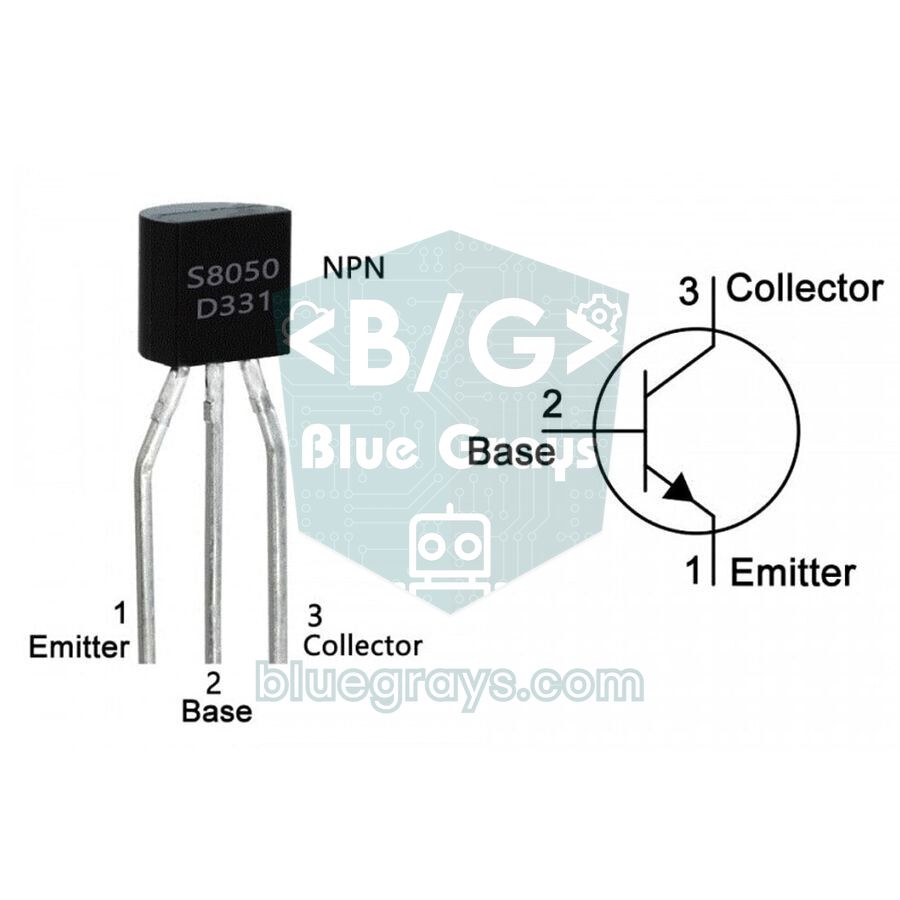
A column pin supplies current to a single LED, but when a layer is switched on, the current of every LED in that layer returns to GND through the same cathode line. On a 3x3x3 cube that's 9 LEDs × 12.7 mA ≈ 115 mA, and on a 4x4x4 cube with 74HC595s it's 16 LEDs × 5 mA ≈ 80 mA. The recommended limit for an Arduino Uno pin is 20 mA and the absolute maximum is 40 mA, so you can't connect a layer line directly to a pin. The solution is an NPN transistor under every layer: the collector goes to the layer line, the emitter to GND, and the base to an Arduino pin through a resistor. When the pin goes HIGH, the transistor saturates and pulls the layer to GND. To switch the transistor fully on, choose a base current of about 1/10 to 1/20 of the collector current: 115 mA needs 6–12 mA, and (5 V − 0.7 V) / 470 Ω ≈ 9 mA falls right in that range. For the details see What Is a Transistor?, and for pinouts the transistor tool.
| Transistor | Continuous IC | Pin order (flat face towards you) | Use in an LED cube |
|---|---|---|---|
| BC547 | 100 mA | C-B-E | Only for low-current cubes; the 115 mA of a 3x3x3 exceeds its limit |
| 2N2222A | 600 mA | E-B-C | Ideal for 3x3x3 and 4x4x4 |
| BC337 | 800 mA | C-B-E | Ideal for 3x3x3 and 4x4x4 |
| IRLZ44N (logic-level MOSFET) | Tens of amps | G-D-S | Big cubes such as 8x8x8; 220 Ω to the gate, 10 kΩ from gate to GND |
Resistor maths: column and base resistors
The column resistor is the only part that limits the LED current, and there's one in each column; you don't need a resistor per LED, because only one LED in a column is lit at any moment. The formula comes from Ohm's law: R = (Vsupply − VLED − VCE(sat)) / ILED. With a 5 V supply, a red LED with a 2.0 V forward voltage and a transistor dropping about 0.2 V when saturated, aiming for 12 mA gives R = (5 − 2.0 − 0.2) / 0.012 ≈ 233 Ω. The nearest standard value, 220 Ω, lets about 12.7 mA through the LED. With a blue LED at 3.1 V, the same 220 Ω gives about 7.7 mA, which is still comfortably visible under multiplexing.
| LED colour | Forward voltage (VF) | 3x3x3, direct from Arduino (5 V) | 4x4x4, 74HC595 (5 V) |
|---|---|---|---|
| Red, yellow | 1.8–2.2 V | 220 Ω (≈12–13 mA) | 470 Ω (≈5–6 mA) |
| True green, blue | 2.9–3.3 V | 180–220 Ω (≈8–9 mA) | 330 Ω (≈4–5 mA) |
| White | 2.9–3.4 V | 180–220 Ω (≈7–9 mA) | 330 Ω (≈4–5 mA) |
On the 74HC595 cube we deliberately choose larger resistors: at most 70 mA in total may flow through this chip's VCC or GND pin, and with a layer on, all eight outputs can be lit at once. 8 × 5.5 mA ≈ 44 mA leaves a safe margin. The average LED current, which sets the perceived brightness, is the instantaneous current divided by the number of layers: 12.7 / 3 ≈ 4.2 mA on a 3x3x3 and 5.5 / 4 ≈ 1.4 mA on a 4x4x4. Today's efficient LEDs are clearly visible indoors at these currents, but in a very bright room a 4x4x4 cube can look a little dim. To calculate with your own LED's values, use the LED resistor and LED voltages tools.
3x3x3 LED cube wiring
| Connection | Arduino Uno / Nano | Note |
|---|---|---|
| Columns 0–8 (anodes) | D2–D10 | 220 Ω series resistor on each column |
| Bottom layer (z = 0) | A0 | To the base of transistor 1 via 470 Ω |
| Middle layer (z = 1) | A1 | To the base of transistor 2 via 470 Ω |
| Top layer (z = 2) | A2 | To the base of transistor 3 via 470 Ω |
| Transistor collectors | — | Each to the cathode wire of its own layer |
| Transistor emitters | GND | All three to a common GND |
| Top view | x = 0 | x = 1 | x = 2 |
|---|---|---|---|
| y = 2 (back) | Column 6 → D8 | Column 7 → D9 | Column 8 → D10 |
| y = 1 (middle) | Column 3 → D5 | Column 4 → D6 | Column 5 → D7 |
| y = 0 (front) | Column 0 → D2 | Column 1 → D3 | Column 2 → D4 |
3x3x3 LED cube Arduino code: animations with arrays
Each frame of the animation is stored as one number per layer. A 3x3x3 layer has 9 LEDs, so a 9-bit value is enough; we store it as a uint16_t, and bit c stands for column c. The frames are written to flash memory with PROGMEM, so even animations with hundreds of frames don't fill the Uno's 2 KB of RAM. The code below needs no extra library.
1// 3x3x3 LED küp: katman çoklama ve dizilerle animasyon / 3x3x3 LED cube: layer multiplexing and array animations
2const byte colPins[9]   = {2, 3, 4, 5, 6, 7, 8, 9, 10};   // sütun anotları, 220 ohm ile / column anodes via 220 ohm
3const byte layerPins[3] = {A0, A1, A2};                     // alt, orta, üst katman transistörü / bottom, middle, top layer transistor
4
5// Her kare 3 katman, her katman 9 bit: bit c = sütun c (c = y*3 + x)
6// Each frame has 3 layers of 9 bits: bit c = column c (c = y*3 + x)
7const uint16_t frames[][3] PROGMEM = {
8  {0b111111111, 0b000000000, 0b000000000},  // 0: alt katman / bottom layer
9  {0b000000000, 0b111111111, 0b000000000},  // 1: orta katman / middle layer
10  {0b000000000, 0b000000000, 0b111111111},  // 2: üst katman / top layer
11  {0b000000000, 0b000010000, 0b000000000},  // 3: yalnız merkez / centre only
12  {0b111101111, 0b101000101, 0b111101111},  // 4: tel kafes, 12 kenar / wireframe, 12 edges
13  {0b010010010, 0b010010010, 0b010010010},  // 5: dönen düzlem, 1. konum / rotating plane, step 1
14  {0b100010001, 0b100010001, 0b100010001},  // 6: dönen düzlem, 2. konum / rotating plane, step 2
15  {0b000111000, 0b000111000, 0b000111000},  // 7: dönen düzlem, 3. konum / rotating plane, step 3
16  {0b001010100, 0b001010100, 0b001010100},  // 8: dönen düzlem, 4. konum / rotating plane, step 4
17  {0b111111111, 0b111111111, 0b111111111}   // 9: hepsi açık / all on
18};
19
20void setup() {
21  for (byte c = 0; c < 9; c++) pinMode(colPins[c], OUTPUT);
22  for (byte z = 0; z < 3; z++) pinMode(layerPins[z], OUTPUT);  // LOW: katmanlar kapalı / LOW: layers off
23}
24
25// Bir kareyi verilen süre boyunca katman katman tarar / scans one frame layer by layer for the given time
26void showFrame(byte f, unsigned int ms) {
27  unsigned long start = millis();
28  while (millis() - start < ms) {
29    for (byte z = 0; z < 3; z++) {
30      uint16_t bits = pgm_read_word(&frames[f][z]);         // katman verisini oku / read the layer data
31      for (byte c = 0; c < 9; c++) digitalWrite(colPins[c], bitRead(bits, c));
32      digitalWrite(layerPins[z], HIGH);                      // katmanı aç / layer on
33      delay(3);                                              // 3 ms göster / show for 3 ms
34      digitalWrite(layerPins[z], LOW);                       // sütunlar değişmeden önce kapat / off before the columns change
35    }
36  }
37}
38
39void loop() {
40  for (byte f = 0; f <= 4; f++) showFrame(f, 500);           // katmanlar, merkez, kafes / layers, centre, wireframe
41  for (byte turn = 0; turn < 4; turn++)                      // düzlemi 4 tur döndür / spin the plane 4 times
42    for (byte f = 5; f <= 8; f++) showFrame(f, 120);
43  showFrame(9, 800);                                         // hepsi açık / all on
44}
The heart of the code is the showFrame() function. For each layer it first writes the column pattern to the pins, then turns on only that layer's transistor for 3 ms and switches the layer off before the columns change. This order matters: if you change the columns while a layer is on, the previous layer's pattern shows up on the new layer for a brief moment and causes ghosting. bitRead(bits, c) returns bit c of the number as 0 or 1, and pgm_read_word() reads the 16-bit value from flash. loop() first shows the layers one by one, then the centre and the 12 edges of the cube, and then spins a vertical plane through four positions to create a pinwheel effect.
Designing your own animations
To draw a new frame, look down at the cube from above and think of each layer as a 3x3 sheet of squared paper. Mark the columns you want lit and write the binary number after 0b from left to right, from bit 8 down to bit 0. The four corners, for example, are columns 0, 2, 6 and 8, which gives 0b101000101. Write the same value to all three layers and you get vertical bars at the four corners; write it only to the middle layer and you get four points floating in the air. If binary numbers are new to you, Number Systems and Bitwise Operations explains the idea in detail. A few techniques that come in handy when you write the code:
- Bit shifting: Shift a layer's value left by 3 bits on a 3x3x3 or by 4 bits on a 4x4x4 and the pattern moves one row back; mask off the overflowing bits with & to make wave and scrolling-text effects.
- Copying layers: Copying the layer array one step down or up gives rain, rising-bubble and lift effects.
- Randomness: Voxels picked with random() that flash briefly create a starfield or sparkle effect.
- Inverting: The ~ operator turns a frame into its negative, and switching quickly between the two gives a flashing highlight.
4x4x4 LED cube: scaling up with the 74HC595
A 4x4x4 cube has 16 columns and 4 layers; driving it directly takes 20 pins, which means every pin of the Uno, D0 and D1 included. If you drive the columns with two daisy-chained 74HC595 shift registers instead, the 16 columns cost only 3 pins (data, clock and latch); add 4 pins for the layers and you're at 7 pins in total. The Q7' output (pin 9) of the first chip goes to the DS input of the second chip, while the clock and latch lines are shared by both chips. Columns 0–7 (the front two rows) connect to the Q0–Q7 outputs of the first chip, and columns 8–15 (the back two rows) to the second chip. The same method scales to 4 chips for a 5x5x5 cube and 8 chips for an 8x8x8 cube.
| Connection | Arduino Uno | ESP32 | Raspberry Pi Pico |
|---|---|---|---|
| DS (14), first chip | D11 | GPIO 23 | GP19 |
| SH_CP (11), shared by both chips | D13 | GPIO 18 | GP18 |
| ST_CP (12), shared by both chips | D10 | GPIO 5 | GP17 |
| OE (13) / MR (10) | GND / 5V | GND / 5V | GND / VBUS |
| VCC (16) / GND (8) | 5V / GND | 5V / GND | VBUS / GND |
| Q7' (9) → DS (14) of the second chip | Chain | Chain | Chain |
| Layer 0–3 transistors (via 470 Ω) | D2, D3, D4, D5 | GPIO 25, 26, 27, 32 | GP10, GP11, GP12, GP13 |
| Chip type | 74HC595 | 74HCT595 | 74HCT595 |
1// 4x4x4 LED küp: 2 adet 74HC595 (16 sütun) + 4 transistörlü katman / 4x4x4 LED cube: two 74HC595s (16 columns) + 4 transistor layers
2const byte DATA_PIN  = 11;                 // 74HC595 DS (14)
3const byte CLOCK_PIN = 13;                 // 74HC595 SH_CP (11)
4const byte LATCH_PIN = 10;                 // 74HC595 ST_CP (12)
5const byte layerPins[4] = {2, 3, 4, 5};    // alttan üste katman transistörleri, 470 ohm ile / layer transistors bottom to top, via 470 ohm
6
7uint16_t cube[4];                          // ekrandaki görüntü: katman başına 16 bit / current image: 16 bits per layer
8
9// Hazır kareler: bit c = sütun c (c = y*4 + x) / ready-made frames: bit c = column c (c = y*4 + x)
10const uint16_t frames[][4] PROGMEM = {
11  {0xFFFF, 0x0000, 0x0000, 0x0000},        // alt katman / bottom layer
12  {0x0000, 0xFFFF, 0x0000, 0x0000},
13  {0x0000, 0x0000, 0xFFFF, 0x0000},
14  {0x0000, 0x0000, 0x0000, 0xFFFF},        // üst katman / top layer
15  {0x9009, 0x0000, 0x0000, 0x9009},        // 8 köşe / 8 corners
16  {0xF99F, 0x9009, 0x9009, 0xF99F},        // tel kafes / wireframe
17  {0x0000, 0x0660, 0x0660, 0x0000}         // içteki 2x2x2 küp / inner 2x2x2 cube
18};
19const byte FRAME_COUNT = sizeof(frames) / sizeof(frames[0]);
20
21void write16(uint16_t v) {                 // 16 biti iki entegreye gönder / send 16 bits to both chips
22  digitalWrite(LATCH_PIN, LOW);
23  shiftOut(DATA_PIN, CLOCK_PIN, MSBFIRST, highByte(v));  // önce uzaktaki entegre / far chip first
24  shiftOut(DATA_PIN, CLOCK_PIN, MSBFIRST, lowByte(v));
25  digitalWrite(LATCH_PIN, HIGH);           // çıkışlara aktar / copy to the outputs
26}
27
28void refresh() {                           // her 2 ms'de sıradaki katmana geç / move to the next layer every 2 ms
29  static byte z = 0;
30  static unsigned long last = 0;
31  if (micros() - last < 2000) return;
32  last = micros();
33  digitalWrite(layerPins[z], LOW);         // eski katmanı kapat / old layer off
34  z = (z + 1) % 4;
35  write16(cube[z]);                        // yeni katmanın sütunları / columns of the new layer
36  digitalWrite(layerPins[z], HIGH);        // yeni katmanı aç / new layer on
37}
38
39void holdFor(unsigned int ms) {            // beklerken küpü yenilemeye devam et / keep refreshing while waiting
40  unsigned long start = millis();
41  while (millis() - start < ms) refresh();
42}
43
44void clearCube() {
45  for (byte z = 0; z < 4; z++) cube[z] = 0;
46}
47
48void setVoxel(byte x, byte y, byte z) {    // tek LED yak, x/y/z = 0..3 / light one LED, x/y/z = 0..3
49  bitSet(cube[z], y * 4 + x);
50}
51
52void loadFrame(byte f) {                   // PROGMEM'deki kareyi yükle / load a frame from PROGMEM
53  for (byte z = 0; z < 4; z++) cube[z] = pgm_read_word(&frames[f][z]);
54}
55
56void sweep() {                             // dikey düzlemi x ekseninde kaydır / sweep a vertical plane along x
57  for (byte x = 0; x < 4; x++) {
58    clearCube();
59    for (byte y = 0; y < 4; y++)
60      for (byte z = 0; z < 4; z++) setVoxel(x, y, z);
61    holdFor(150);
62  }
63}
64
65void rain(byte steps) {                    // yağmur: damlalar yukarıdan düşer / rain: drops fall from the top
66  clearCube();
67  for (byte s = 0; s < steps; s++) {
68    for (byte z = 0; z < 3; z++) cube[z] = cube[z + 1];   // her şeyi bir kat indir / move everything down a layer
69    cube[3] = bit(random(16)) | bit(random(16));         // üstte 1-2 yeni damla / 1-2 new drops on top
70    holdFor(120);
71  }
72}
73
74void setup() {
75  pinMode(DATA_PIN, OUTPUT);
76  pinMode(CLOCK_PIN, OUTPUT);
77  pinMode(LATCH_PIN, OUTPUT);
78  for (byte z = 0; z < 4; z++) pinMode(layerPins[z], OUTPUT);
79  randomSeed(analogRead(A0));              // boştaki A0'dan rastgele tohum / random seed from the unconnected A0
80}
81
82void loop() {
83  for (byte f = 0; f < FRAME_COUNT; f++) {
84    loadFrame(f);
85    holdFor(500);
86  }
87  for (byte i = 0; i < 3; i++) sweep();
88  rain(80);
89}
In this version the scanning happens in the refresh() function with a non-blocking design: every time it's called it uses micros() to check whether 2 ms have passed; if so, it switches the old layer off, sends the new layer's 16 bits to the two chips and switches the new layer on. That way the animation code only changes the cube[] array and never deals with refreshing the display. holdFor() keeps calling refresh() while it waits, so you shouldn't use a long delay() anywhere in the program. setVoxel(x, y, z) lets you light a single LED by its coordinates; sweep() uses it to move a vertical plane through the cube, and rain() copies the layers one step down and adds random drops at the top. You'll find the difference between delay() and millis() in millis() vs delay(), and how to move the scanning into a timer interrupt in Arduino Interrupts.
LED cube with the ESP32
The ESP32's pins output 3.3 V. That isn't enough to drive blue and white LEDs, whose forward voltage is around 3 V, directly; after the drop across the resistor and the transistor almost nothing is left. That's why the cleanest solution on the ESP32 is to drive the columns through a 74HCT595 powered from 5 V: the HCT family treats even 2 V as HIGH, so it reads 3.3 V signals without trouble, while the LEDs are fed from 5 V. Keep 470 Ω on the bases of the layer transistors; (3.3 − 0.7) / 470 ≈ 5.5 mA is enough for an 80 mA layer current. The 4x4x4 code above compiles on the ESP32 as it is; you only need to change the pin constants to the values in the table (23, 18, 5 and 25, 26, 27, 32). If you like, you can also use the ESP32's Wi-Fi to pick animations from a web page on your phone; to get started, see What Is the ESP32?.
LED cube with the Raspberry Pi Pico and MicroPython
The Pico is a 3.3 V board too, and with the default setting its pins supply only a few milliamps, so you use the same 74HCT595 circuit. Power the chips and LEDs from VBUS (pin 40), which carries the 5 V from USB. In MicroPython the 16 bits are sent with hardware SPI: SPI0's GP18 (SCK) and GP19 (MOSI) pins drive the clock and data lines, and GP17 drives the latch. The code follows the same logic: show() scans a frame layer by layer for the given time, and in the rain effect list slicing (cube[1:]) moves every layer one step down. For setup and first steps, see What Is the Raspberry Pi Pico?.
1# Pico + 2 adet 74HCT595 ile 4x4x4 LED küp / 4x4x4 LED cube with a Pico + two 74HCT595s
2from machine import Pin, SPI
3import time
4import random
5
6# GP18 = SCK -> SH_CP, GP19 = MOSI -> DS; GP16 (MISO) boş kalır / GP16 (MISO) stays unconnected
7spi = SPI(0, baudrate=1000000, polarity=0, phase=0, sck=Pin(18), mosi=Pin(19))
8latch = Pin(17, Pin.OUT, value=0)                                # ST_CP
9layers = [Pin(n, Pin.OUT, value=0) for n in (10, 11, 12, 13)]    # alttan üste, 470 ohm ile / bottom to top, via 470 ohm
10
11def write16(v):
12    latch.value(0)
13    spi.write(bytes((v >> 8, v & 0xFF)))    # önce uzaktaki entegre / far chip first
14    latch.value(1)                          # çıkışlara aktar / copy to the outputs
15
16def show(frame, ms):
17    # kareyi ms boyunca katman katman tara / scan the frame layer by layer for ms
18    end = time.ticks_add(time.ticks_ms(), ms)
19    while time.ticks_diff(end, time.ticks_ms()) > 0:
20        for z in range(4):
21            write16(frame[z])
22            layers[z].value(1)              # katmanı aç / layer on
23            time.sleep_us(2000)
24            layers[z].value(0)              # sütunlar değişmeden kapat / off before the columns change
25
26FRAMES = [
27    [0x9009, 0x0000, 0x0000, 0x9009],       # 8 köşe / 8 corners
28    [0xF99F, 0x9009, 0x9009, 0xF99F],       # tel kafes / wireframe
29    [0x0000, 0x0660, 0x0660, 0x0000],       # içteki küp / inner cube
30]
31
32while True:
33    for f in FRAMES:
34        show(f, 600)
35    cube = [0, 0, 0, 0]
36    for _ in range(60):                     # yağmur: her şey bir kat iner / rain: everything drops a layer
37        drop = (1 << random.getrandbits(4)) | (1 << random.getrandbits(4))
38        cube = cube[1:] + [drop]
39        show(cube, 120)
Bigger cubes: 5x5x5 and 8x8x8
As the cube grows, two problems grow with it. The first is current: an 8x8x8 cube has 64 LEDs per layer, and at 10 mA per LED the layer current is 640 mA; that's no longer a job for a small TO-92 transistor but for a logic-level MOSFET. The second is scan time: to keep 100 Hz with 8 layers, each layer gets 1.25 ms and 64 bits (8 bytes) must be sent per layer; shiftOut() is too slow for this, so hardware SPI is a must. On top of that, each LED is lit only 1/8 of the time, so brightness drops; big cubes need stronger column drivers and an external 5 V adapter instead of USB (see Powering an Arduino). That's why your first cube should be a 3x3x3 or 4x4x4; you'll master the technique before soldering 512 LEDs.
Alternative: a colour LED cube with WS2812B
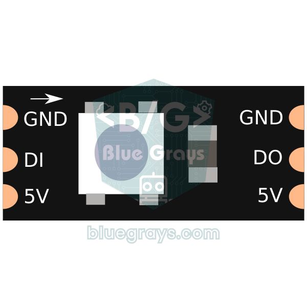
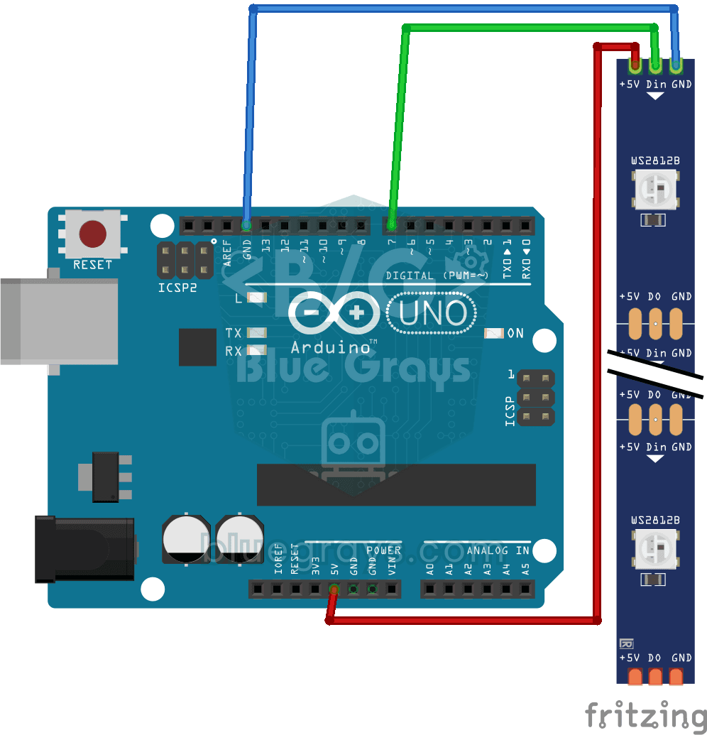
If you'd rather pick the colour of every LED individually instead of building a single-colour cube, you can use addressable LEDs such as the WS2812B. Each of these LEDs has its own driver chip, so there's no need for multiplexing, transistors or column resistors: the 64 LEDs are daisy-chained with 5 V, GND and a data line and driven from a single pin. For a cube you use 4-leg 5 mm addressable LEDs (such as the PL9823 or APA106) or pieces cut from a WS2812B strip. The price is current: about 60 mA per LED at full white, which is 3.8 A for 64 LEDs. So use a 5 V 4 A adapter, add a 1000 µF capacitor on the supply and a 330 Ω resistor on the data line, and limit the brightness in software. The code uses the Adafruit NeoPixel library.
1// WS2812B ile 4x4x4 RGB LED küp / 4x4x4 RGB LED cube with WS2812B
2#include <Adafruit_NeoPixel.h>
3
4const byte DATA_PIN = 6;                   // 330 ohm ile ilk LED'in DIN ucuna / to the first LED's DIN via 330 ohm
5const byte N = 4;
6Adafruit_NeoPixel cube(N * N * N, DATA_PIN, NEO_GRB + NEO_KHZ800);
7
8uint16_t idx(byte x, byte y, byte z) {     // koordinattan zincirdeki sıraya / coordinate to position in the chain
9  return z * 16 + y * 4 + x;               // düz (zikzaksız) kablolama varsayılır / assumes straight, non-zigzag wiring
10}
11
12void setup() {
13  cube.begin();
14  cube.setBrightness(40);                  // parlaklığı ve akımı sınırla (0-255) / limit brightness and current (0-255)
15}
16
17void loop() {
18  static uint16_t hue = 0;
19  for (byte z = 0; z < N; z++)
20    for (byte y = 0; y < N; y++)
21      for (byte x = 0; x < N; x++)         // her katman farklı tonda / each layer gets a different hue
22        cube.setPixelColor(idx(x, y, z), cube.gamma32(cube.ColorHSV(hue + z * 8192U)));
23  cube.show();
24  hue += 256;                              // gökkuşağını kaydır / shift the rainbow
25  delay(20);
26}
The idx() function in the code converts an x, y, z coordinate into the position in the chain and assumes you wired every row in the same direction. If you ran the wiring in a zigzag, you'll need to use 3 − x instead of x on odd rows. Some 5 mm addressable LEDs expect colours in RGB order; if you see green instead of red, change NEO_GRB to NEO_RGB. setBrightness(40) reduces the brightness to about 16%, so even in the worst case the current stays around 0.6 A.
| Feature | Single-colour LED cube | WS2812B LED cube |
|---|---|---|
| Colour | One colour (the LED's own) | 16 million colours, set per LED |
| Pins used (4x4x4) | 7 (with 74HC595) | 1 |
| Extra parts | Transistors, resistors, 74HC595 | Capacitor, data resistor, strong adapter |
| Soldering work | 2 legs per LED | 4 legs per LED, more wires |
| Brightness control | On/off (per-LED PWM is hard) | 256 levels for every LED |
| Current (4x4x4) | Around 100 mA, USB is enough | Up to ≈3.8 A, external supply required |
| What it teaches | Multiplexing, transistors, bit operations | Addressing, hue, power management |
LED cube project ideas
- Music-reactive cube: Raise the number of lit layers according to the sound level measured with a sound sensor to make a three-dimensional equaliser.
- 3D snake game: Steer the snake along three axes on a 4x4x4 cube with a joystick and a button; for more game ideas, see Arduino game projects.
- Dice cube: When you press a button, the voxels shuffle quickly and the cube shows a number from 1 to 6 as a dot pattern.
- Science fair project: Explain persistence of vision by stretching the layer time with a potentiometer and showing the moment flicker starts; for more ideas, see science fair project ideas.
- Choosing animations from your phone: Let every letter you send with an HC-05 Bluetooth module start a different animation.
- Colourful night light: Set up slow colour fades on a WS2812B cube; if you're using an ESP32, control the effects from your phone with WLED.
Common mistakes and how to fix them
| Symptom | Likely cause | Fix |
|---|---|---|
| A single LED never lights | The LED is reversed or dead, or a leg joint is broken | Check the cathode direction, test the LED with a coin cell, replace it if needed |
| LEDs that should be off glow faintly (ghosting) | The columns change while a layer is on, or the cube has a reversed LED | Switch the layer off first, then write the columns; if the code is right, find the reversed LED |
| LEDs flicker or go out when you touch the cube | Cold solder joint: a dull, grainy, ball-shaped joint | Reheat the joint with a clean iron tip and add a little fresh solder |
| A whole layer stays dark | The transistor legs are reversed (E-B-C mixed up with C-B-E) or the base resistor is disconnected | Check the pin order in the datasheet and measure the base connection |
| A whole column stays dark | The column isn't soldered to the base, or the resistor or pin is wrong | Measure the column end to end with a multimeter and check the pin array in the code |
| The cube flickers | The layer time is too long, or there's a Serial.print() or delay() in the scan loop | Set the layer time to 2–3 ms and remove code that blocks the scan |
| The cube is very dim | The resistors are too large, blue LEDs are driven from 3.3 V, or there are too many layers | Recalculate the resistor; on 3.3 V boards power a 74HCT595 from 5 V |
| The sketch won't upload | An LED is connected to D0 or D1 | Start the columns at D2, or disconnect these wires while uploading |
The LED cube is one of the rare projects that teaches soldering, transistors, resistor maths, multiplexing and bit operations all at once. Start with a 3x3x3, and once the code and the animation logic click, move on to a 4x4x4 with the 74HC595, or to WS2812B if you want colour. If you'd like to try the idea of lighting LEDs in sequence on a straight row first, Arduino Knight Rider and running LEDs is a good warm-up. In the BlueGrays app you'll find running LED, Knight Rider, WS2812B animation and LED matrix projects with step-by-step circuit diagrams and code.
Frequently asked questions
How many LEDs and pins does an LED cube need?
A 3x3x3 cube needs 27 LEDs and a 4x4x4 cube needs 64; it's worth buying a few spares. With layer-column multiplexing, a 3x3x3 cube needs 9 columns plus 3 layers, so 12 pins. A 4x4x4 cube takes 20 pins when driven directly, but if you drive the columns with two 74HC595s the total drops to 7 pins.
What resistor should I use in an LED cube?
There's one resistor per column; for a 3x3x3 cube driven directly by an Arduino at 5 V, 220 Ω is a common and safe value. On a 74HC595 cube, use 330 Ω for blue and white LEDs and 470 Ω for red and yellow LEDs so you stay under the chip's 70 mA total limit. For your own value, apply R = (Vsupply − VLED − 0.2 V) / ILED.
Why are the layers of an LED cube driven by transistors?
When a layer is switched on, the current of every LED in that layer returns to GND through a single line; on a 3x3x3 cube that's more than 100 mA. Because the recommended limit of an Arduino pin is 20 mA, the layer line is pulled to GND by an NPN transistor such as a 2N2222A or BC337. A 470 Ω base resistor is enough.
Why is my LED cube flickering?
Flicker appears when the scan rate is too low. The refresh rate is 1 / (number of layers × layer time) and should be above 100 Hz, so keep the layer time at 2–3 ms and don't put a long delay() or Serial.print() in the scan loop. If the cube only flickers when you touch it, the problem is most likely a cold solder joint.
Why do LEDs light up that should be off?
This is called ghosting, and it has two main causes. Changing the column values while a layer is on carries the previous pattern onto the new layer for a moment; switch the layer off first, then write the columns. If the code is right, a reversed LED in the cube may be opening a current path into other layers.
Can you build an 8x8x8 LED cube with an Arduino Uno?
Yes, but the pins aren't enough on their own: you need a 74HC595 chain or similar drivers for the 64 columns, logic-level MOSFETs for the 8 layers and hardware SPI for fast scanning. Soldering 512 LEDs also takes days. Mastering the technique on a 3x3x3 or 4x4x4 cube first is the best way to go.
Projects to build after reading this
See all projects
LED Chaser
Lights that switch on one after another, as if they were running. The Arduino lights six LEDs one at a time; each glows for a brief moment and goes out, so the light walks from start to end and then s

Knight Rider LED Effect
The classic scanner light: a dot of light slides from one end of six LEDs to the other and then comes back. The Arduino lights each LED for a tenth of a second before moving on, turns around at each e

Knight Rider LED Effect with Adjustable Speed
A light runs from one end of six LEDs to the other, turns around and runs back again. Turn the potentiometer knob and you change the speed of that run instantly: with the knob at one end the light alm
Using a WS2812B LED Strip
Meet a smart LED strip where you can colour every single light on its own. The Arduino first lights the first five LEDs red, a second later turns the other five blue, then switches them all off and st

WS2812B Animation 1
On a strip of 56 LEDs, all the colours of the rainbow line up side by side and flow without ever stopping, as if a river of light were gliding along the strip. Each LED glows in a slightly different c

WS2812B Animation 2
Set up a light show in your room that changes colors all by itself. The Arduino keeps colors flowing along a 30-LED strip and switches to a new color set every few seconds: rainbow, purple and green s

Pixel Snake 8x8 Matrix
Build the classic snake game with your own hands and play it. On a colorful 8x8 light matrix, you steer a green snake with a joystick and eat red apples; with every apple the snake grows, speeds up a

4x 32x8 LED Matrix - 6-Animation Pack
Four 32x8 LED panels stacked on top of each other form a square screen where six animations play in turn: falling digital rain, a growing spiral, cells that are born and die all by themselves, ripplin