
Arduino Servo Motor Projects: 15 Ideas, SG90 vs MG996R
15 Arduino servo motor projects: radar, robot arm, door lock, solar tracker and pet feeder; how to pick SG90, MG90S or MG996R, power them and use a PCA9685.
Arduino servo motor projects are the easiest way to make something genuinely move: with a single wire you give the servo an angle, it goes there and holds. In this guide we've collected 15 servo motor projects, from an ultrasonic radar to a robot arm, an RFID door lock, a solar tracker and an automatic pet feeder. For every project you'll find, in one table, which servo to choose, how many you need, whether to drive them straight from the Arduino or through a PCA9685 driver, and how to power them.
Before the projects, we'll look at the differences between the SG90, MG90S and MG996R, how to pick a power supply for a given number of servos, and how many servos an Arduino Uno, ESP32 and Raspberry Pi Pico can drive at once. After that come compiled, ready-to-use code templates for the radar, robot arm and solar tracker projects. If servos are new to you, we suggest reading What Is a Servo Motor? first.
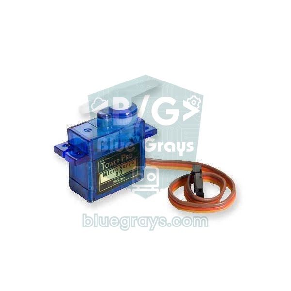
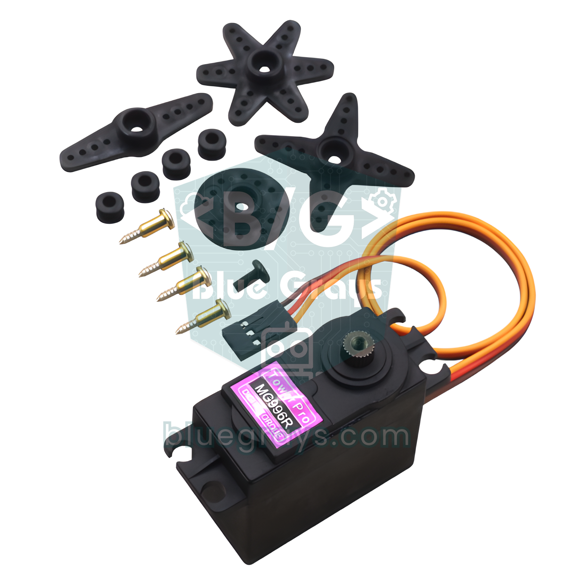
Which servo: SG90, MG90S or MG996R?
The first number to check when choosing a servo is torque: it's given in kg·cm and tells you how many kilograms the servo can hold 1 cm from the shaft. The longer the arm, the less it can lift, in direct proportion; a 1.8 kg·cm SG90 holds barely 300 grams at the end of a 6 cm arm, and not continuously. The second thing is gear material: plastic gears strip under strain, while metal gears survive knocks. The third is current: a big servo needs a big power supply. In practice, the SG90 is right for light lids and turning sensors, the MG90S for small mechanisms that work often or under load, and the MG996R for a robot arm's shoulder and heavy lids.
| Model | Torque | Gears | Stall current | Recommended supply | Typical project |
|---|---|---|---|---|---|
| SG90 | 1.8 kg·cm (4.8 V) | Plastic | 650-750 mA | 5 V | Radar, pan-tilt, small lid |
| MG90S | 1.8-2.2 kg·cm | Metal | 0.7-1 A | 5-6 V | Door lock, gripper, spider robot |
| MG996R | 9.4-11 kg·cm | Metal, dual bearings | 2.5 A (6 V) | 6 V, 3 A per servo | Robot arm shoulder, curtain, heavy lid |
| FS90R (360°) | 1.5 kg·cm | Plastic | up to 800 mA | 5 V | Wheels, turntable |
Servo power table: how many servos, how much current?
Most problems in servo projects come from power, not from code. The moment a servo starts moving it pulls a short current spike; if the Arduino's 5V pin, fed from USB, can't supply it, the voltage sags, the board resets and the servo jitters. The rule is simple: you can run a single lightly loaded SG90 from the Arduino's 5V pin, but for anything more, power the servos from an external 5-6 V supply, connect the supply's negative to the Arduino's GND and add a 470-1000 µF capacitor across the servo rail. To size the supply, add up the servos' running currents and leave at least 50% headroom.
| Setup | Running current (approx.) | Recommended supply |
|---|---|---|
| 1 × SG90, light load | 100-250 mA | The Arduino's 5V pin is enough |
| 2 × SG90 or MG90S | 0.3-0.6 A | External 5 V, 2 A |
| 4 × MG90S (small robot arm) | 0.6-1.2 A | External 5 V, 3 A |
| 1 × MG996R | 0.5-0.9 A (2.5 A stalled) | 6 V, 3 A |
| 6 × MG996R (large robot arm) | 3-5.4 A | 6 V, 10 A switching supply |
| 12 × MG90S (spider robot) | 1.8-3.6 A | 5-6 V, 5 A, or a 2S LiPo with a 5 A BEC |
Drive servos directly or with a PCA9685?
Driving a few servos straight from the microcontroller's pins is the simplest approach. The Arduino Uno's Servo library uses Timer1 to generate pulses for up to 12 servos, but while it does, analogWrite stops working on pins 9 and 10. The ESP32 gives each servo its own hardware PWM channel, and the Pico has 16 PWM channels. Once you go past 5 or 6 servos, when the pulses start to jitter, or when you need the pins for other jobs, the PCA9685 driver board steps in: it drives 16 servos using just two I2C pins, and because it generates the pulses with its own clock, it takes the load off the microcontroller. We cover the setup in detail in the PCA9685 servo driver guide.
| Platform | Library | Direct servos | Watch out for |
|---|---|---|---|
| Arduino Uno / Nano | Servo (built in) | Up to 12 | Uses Timer1: analogWrite doesn't work on D9 and D10 |
| Arduino Mega | Servo (built in) | Up to 48 | Lots of servos still need external power |
| ESP32 | ESP32Servo | Up to 16 | GPIO 18, 19, 21, 22, 23, 25, 26, 27 are safe; 34-39 are input only |
| Raspberry Pi Pico | machine.PWM (MicroPython) | Up to 16 | Two pins on the same PWM slice share a frequency; fine at 50 Hz |
| PCA9685 (with any board) | Adafruit PWM Servo Driver | 16 per board, up to 62 boards chained | Servo power goes into the board's V+ terminal |
15 servo motor projects: servo, count and driving method
| # | Project | Servo | Count | Driving method | Level |
|---|---|---|---|---|---|
| 1 | Angle control with a potentiometer | SG90 | 1 | Direct | Beginner |
| 2 | Ultrasonic radar | SG90 | 1 | Direct | Beginner |
| 3 | Automatic bin lid | MG90S | 1 | Direct | Beginner |
| 4 | Automatic pet feeder | MG90S or MG996R | 1 | Direct | Intermediate |
| 5 | RFID or keypad door lock | MG90S | 1 | Direct | Intermediate |
| 6 | Servo needle thermometer | SG90 | 1 | Direct | Beginner |
| 7 | Turning head for an obstacle-avoiding robot | SG90 | 1 | Direct | Intermediate |
| 8 | Joystick pan-tilt camera mount | SG90 | 2 | Direct | Beginner |
| 9 | Solar tracker | MG90S | 2 | Direct | Intermediate |
| 10 | Level crossing barrier (model) | SG90 | 2 | Direct | Beginner |
| 11 | Wi-Fi curtain or vent opener | MG996R | 1 | Direct (ESP32) | Intermediate |
| 12 | Self-levelling platform with an MPU6050 | MG90S | 2 | Direct | Advanced |
| 13 | 4-axis desktop robot arm | MG90S or SG90 | 4 | Direct or PCA9685 | Intermediate |
| 14 | 6-axis robot arm | MG996R and MG90S | 6 | PCA9685 | Advanced |
| 15 | Quadruped spider robot | MG90S | 12 | PCA9685 | Advanced |
Single-servo projects (1-7)
- 1. Angle control with a potentiometer: the "hello world" of servos. You map the potentiometer's 0-1023 reading to 0-180 degrees with map() and write it to the servo. The code and wiring are in What Is a Servo Motor?; you'll reuse the same logic in every project from here on.
- 2. Ultrasonic radar: an HC-SR04 distance sensor is stuck on top of an SG90, the servo sweeps between 15 and 165 degrees, and the distance at each angle is sent over the serial port. A Processing sketch on the computer turns the data into the classic green radar screen. Details are in the Arduino radar project, and the code is below.
- 3. Automatic bin lid: an HC-SR04 at the front sees a hand closer than 20 cm, the servo opens the lid and closes it a few seconds later. If the lid is heavy, use a metal-gear MG90S instead of an SG90; see the smart bin guide.
- 4. Automatic pet feeder: at set times the servo opens the flap under the food hopper for a few seconds. An RTC module provides the time, and how long the flap stays open sets the portion. Auger (screw) feeders need more torque, so an MG996R or a 360-degree servo is the better choice; see the automatic pet feeder.
- 5. RFID or keypad door lock: when the right RFID card is scanned or the right code is entered on a keypad, the servo slides the bolt. Because the bolt has friction, a metal-gear MG90S lasts much longer.
- 6. Servo needle thermometer: fix a needle to the servo horn and put a card with a 0-40 °C scale behind it; the temperature measured by a DHT11 is mapped to an angle with map(). The same idea works as a humidity, sound level or subscriber count gauge.
- 7. Turning head for an obstacle-avoiding robot: when the robot stops, the HC-SR04 on the servo looks left and right, and the robot turns toward the clearer side. This simple addition makes it far smarter than a robot with a fixed sensor; see the obstacle-avoiding robot.
Two-servo projects (8-12)
- 8. Joystick pan-tilt camera mount: two SG90s are mounted one on top of the other: the lower one turns horizontally (pan) and the upper one vertically (tilt). The X and Y axes of a joystick module are mapped to the two servos; on top you can fit a small camera, a laser or a sensor.
- 9. Solar tracker: four LDRs measure which side the light is stronger on, and two servos turn the panel horizontally and vertically toward the brightest direction. Wind loads the panel arm, so MG90S servos are a good idea. Details are in the solar tracker guide, and the ESP32 code is below.
- 10. Level crossing barrier: for a model railway or a school project, two SG90s lower and raise the barriers, red LEDs flash alternately and a buzzer sounds a warning. An infrared sensor or a reed switch detects the approaching train; slowing the servo down gives a realistic effect.
- 11. Wi-Fi curtain or vent opener: an ESP32 runs a small web server, and tapping a button on your phone makes an MG996R pull the curtain cord or move a ventilation flap. Because it's an MG996R, an external 6 V supply is a must.
- 12. Self-levelling platform with an MPU6050: the MPU6050 accelerometer measures the platform's tilt, and two servos correct it in the opposite direction to keep the surface level. It makes a simple gimbal that keeps a glass of water or a small camera steady; fast response needs MG90S servos and a good filter.
Multi-servo projects: robot arm and spider robot (13-15)
- 13. 4-axis desktop robot arm: four servos handle the base, shoulder, elbow and gripper. For small acrylic or 3D-printed arms MG90S servos are enough, and all four can be driven directly from the Uno; the servos should run from an external 5 V 3 A supply. You can add manual control with potentiometers, a joystick, or recorded movements that play back; see the Arduino robot arm.
- 14. 6-axis robot arm: bigger metal arms use MG996R servos for the base, shoulder and elbow and MG90S servos for the wrist and gripper. Driving all six through a PCA9685 tidies up the wiring; a 6 V 10 A supply and code that moves the servos one after another rather than all at once keep the current spikes down. For the shoulder load, check the MG996R torque table.
- 15. Quadruped spider robot: with three joints per leg you need 12 servos, and at that count a PCA9685 is practically mandatory. Weight matters, so MG90S servos are preferred, and the robot runs on a 2S LiPo battery with a 5 A BEC. Walking is done with a table of poses that changes each leg's angles in sequence; the robot arm template below is a good starting point for that too.
Common wiring: Arduino Uno, ESP32 and Pico
| Servo wire | Arduino Uno | ESP32 | Raspberry Pi Pico | External 5-6 V supply |
|---|---|---|---|---|
| Brown / black (GND) | GND | GND | GND | Negative (-) |
| Red (V+) | 5V (single SG90 only) | Not connected | Not connected | Positive (+) |
| Orange / yellow (signal) | D9 | GPIO 18 | GP15 | Not connected |
| Supply GND | GND (common) | GND (common) | GND (common) | Negative (-) |
Project 2 code: Arduino ultrasonic radar
The servo goes to D9, the HC-SR04's TRIG to D10 and ECHO to D11. The servo stops every 2 degrees, waits 30 ms and measures the distance; the result is printed to the serial port as "angle,distance". Processing's radar screen or the Arduino IDE's Serial Plotter can read that format directly. The 30 ms timeout passed to pulseIn corresponds to about 5 metres; if no echo comes back, -1 is printed. The distance maths is explained in the HC-SR04 guide.
1#include <Servo.h>
2
3const int SERVO_PIN = 9;     // servo sinyali / servo signal
4const int TRIG_PIN = 10;     // HC-SR04 TRIG
5const int ECHO_PIN = 11;     // HC-SR04 ECHO
6
7Servo radar;
8
9int readDistanceCm() {
10  digitalWrite(TRIG_PIN, LOW);
11  delayMicroseconds(2);
12  digitalWrite(TRIG_PIN, HIGH);                        // 10 µs tetik darbesi / 10 µs trigger pulse
13  delayMicroseconds(10);
14  digitalWrite(TRIG_PIN, LOW);
15  unsigned long us = pulseIn(ECHO_PIN, HIGH, 30000UL); // en fazla 30 ms (~5 m) / max 30 ms (~5 m)
16  if (us == 0) return -1;                              // yankı yok / no echo
17  return us * 0.0343 / 2;                              // µs -> cm
18}
19
20void scanTo(int angle) {
21  radar.write(angle);
22  delay(30);                                           // servo yerine otursun / let the servo settle
23  int d = readDistanceCm();
24  Serial.print(angle);                                 // "açı,mesafe" satırı / "angle,distance" line
25  Serial.print(',');
26  Serial.println(d);
27}
28
29void setup() {
30  Serial.begin(9600);
31  pinMode(TRIG_PIN, OUTPUT);
32  pinMode(ECHO_PIN, INPUT);
33  radar.attach(SERVO_PIN);
34}
35
36void loop() {
37  for (int a = 15; a <= 165; a += 2) scanTo(a);       // soldan sağa / left to right
38  for (int a = 165; a >= 15; a -= 2) scanTo(a);       // sağdan sola / right to left
39}
Project 13 code: a multi-servo robot arm without delay
In a robot arm, all the joints have to move at the same time and smoothly. If you write each servo's target angle directly with write(), the servos snap there at full speed, the arm shakes and the current spikes grow. The template below moves each joint toward its target one degree at a time using millis(); the STEP_MS array sets each joint's speed. Add rows to the POSES table to write your own movement sequence, and use the same structure for a pan-tilt, a barrier or a spider robot.
1#include <Servo.h>
2
3// 4 eksenli robot kol: taban, omuz, dirsek, kıskaç / 4-axis robot arm: base, shoulder, elbow, gripper
4const byte JOINTS = 4;
5const byte PINS[JOINTS] = {3, 5, 6, 9};
6const unsigned int STEP_MS[JOINTS] = {15, 20, 20, 8};   // 1 derece için bekleme (ms) / wait per degree (ms)
7
8// Hareket sırası: her satır bir poz / move sequence: each row is a pose
9const int POSES[][JOINTS] = {
10  {90, 90, 90, 30},     // başlangıç / home
11  {40, 120, 60, 30},    // nesneye uzan / reach the object
12  {40, 120, 60, 90},    // kıskacı kapat / close the gripper
13  {140, 80, 100, 90},   // taşı / carry
14  {140, 80, 100, 30}    // bırak / release
15};
16const byte POSE_COUNT = sizeof(POSES) / sizeof(POSES[0]);
17
18Servo servos[JOINTS];
19int current[JOINTS], target[JOINTS];
20unsigned long lastStep[JOINTS];
21byte pose = 0;
22
23// Servoyu hedefe 1 derece yaklaştırır, delay kullanmaz / moves a servo 1 degree closer, no delay
24bool updateJoint(byte i) {
25  if (current[i] == target[i]) return true;            // hedefte / at target
26  if (millis() - lastStep[i] < STEP_MS[i]) return false;
27  lastStep[i] = millis();
28  current[i] += (target[i] > current[i]) ? 1 : -1;
29  servos[i].write(current[i]);
30  return current[i] == target[i];
31}
32
33void setup() {
34  for (byte i = 0; i < JOINTS; i++) {
35    current[i] = target[i] = POSES[0][i];
36    servos[i].write(current[i]);                       // attach öncesi başlangıç açısı / start angle before attach
37    servos[i].attach(PINS[i]);
38  }
39  delay(1000);
40}
41
42void loop() {
43  bool allDone = true;
44  for (byte i = 0; i < JOINTS; i++) {
45    if (!updateJoint(i)) allDone = false;              // hepsi aynı anda hareket eder / all move together
46  }
47  if (allDone) {                                       // poz tamam, sıradakine geç / pose reached, next one
48    delay(500);
49    pose = (pose + 1) % POSE_COUNT;
50    for (byte i = 0; i < JOINTS; i++) target[i] = POSES[pose][i];
51  }
52}
Calling write() before attach() stops the servo from jumping to 90 degrees at power-up before heading to the start pose. The servos are on D3, D5, D6 and D9; because the Servo library can use any digital pin, the pin doesn't need a PWM mark. If the Arduino resets while the arm moves, the problem is power, not code; work through the checklist in the servo jitter guide.
Project 9 code: solar tracker with an ESP32
The Arduino Servo library doesn't work on the ESP32; install the ESP32Servo library instead, which runs the same code on both the 2.x and 3.x cores. Each of the four LDRs goes between 3V3 and an analog pin, with a 10 kΩ resistor from that pin to GND; the reading rises as the light gets brighter. We used ADC1 pins (32-35) for the LDRs because ADC2 pins can't be read while Wi-Fi is on. If the panel turns the wrong way, your servo mounting is different; just swap the 1 and -1 in the code. How LDRs measure light is covered in the LDR light sensor guide.
1#include <ESP32Servo.h>
2
3const int PAN_PIN = 18;      // yatay servo / horizontal servo
4const int TILT_PIN = 19;     // dikey servo / vertical servo
5// LDR'ler ADC1 pinlerinde (Wi-Fi ile çakışmaz) / LDRs on ADC1 pins (no Wi-Fi conflict)
6const int LDR_TL = 32, LDR_TR = 33, LDR_BL = 34, LDR_BR = 35;
7const int TOLERANCE = 80;    // bu farkın altında hareket etme / ignore smaller differences
8
9Servo pan, tilt;
10int panAngle = 90, tiltAngle = 45;
11
12void setup() {
13  analogReadResolution(12);                 // 0-4095
14  pan.setPeriodHertz(50);                   // standart servo 50 Hz / standard servo 50 Hz
15  tilt.setPeriodHertz(50);
16  pan.attach(PAN_PIN, 500, 2400);           // darbe aralığı (µs) / pulse range (µs)
17  tilt.attach(TILT_PIN, 500, 2400);
18  pan.write(panAngle);
19  tilt.write(tiltAngle);
20}
21
22void loop() {
23  int tl = analogRead(LDR_TL), tr = analogRead(LDR_TR);
24  int bl = analogRead(LDR_BL), br = analogRead(LDR_BR);
25  int top = (tl + tr) / 2, bottom = (bl + br) / 2;
26  int left = (tl + bl) / 2, right = (tr + br) / 2;
27
28  // Daha aydınlık tarafa 1 derece dön / turn 1 degree toward the brighter side
29  if (abs(left - right) > TOLERANCE) panAngle += (left > right) ? 1 : -1;
30  if (abs(top - bottom) > TOLERANCE) tiltAngle += (top > bottom) ? 1 : -1;
31  panAngle = constrain(panAngle, 5, 175);
32  tiltAngle = constrain(tiltAngle, 10, 90);
33
34  pan.write(panAngle);
35  tilt.write(tiltAngle);
36  delay(25);
37}
Servo with a Raspberry Pi Pico (MicroPython)
The Pico needs no extra library: machine.PWM generates a 50 Hz signal and you set the pulse width in nanoseconds. The set_angle() function below maps 0-180 degrees to a 500-2400 µs range; if your servo buzzes at the ends, narrow those limits. The Pico's pins output 3.3 V, and the SG90, MG90S and MG996R all work fine with that signal level, but the servo's power must still come from VBUS (USB 5 V) or an external supply. By applying the same function to a list of PWM objects, you can port every project above to the Pico.
1from machine import Pin, PWM
2import time
3
4servo = PWM(Pin(15))         # GP15 sinyal / GP15 signal
5servo.freq(50)               # 50 Hz = 20 ms periyot / 20 ms period
6
7def set_angle(angle, min_us=500, max_us=2400):
8    angle = max(0, min(180, angle))                 # 0-180 arası sınırla / clamp to 0-180
9    us = min_us + (max_us - min_us) * angle / 180   # açı -> darbe (µs) / angle -> pulse (µs)
10    servo.duty_ns(int(us * 1000))                   # µs -> ns
11
12while True:
13    for a in range(0, 181, 2):                      # 0 -> 180 derece / degrees
14        set_angle(a)
15        time.sleep_ms(15)
16    for a in range(180, -1, -2):                    # 180 -> 0 derece / degrees
17        set_angle(a)
18        time.sleep_ms(15)
Common mistakes in servo projects
- The Arduino resets when the servo moves: the servos are powered from the USB-fed 5V pin. Use an external supply, a common GND and a 470-1000 µF capacitor.
- The servo buzzes and heats up at the ends: at 0 or 180 degrees it's pushing against the mechanical stop. Narrow the range to 5-175 degrees or calibrate the pulse limits in attach().
- The servo jitters: weak power, long thin wires or a noisy potentiometer. Use thicker wire, filter the reading and add a deadband that ignores small changes.
- analogWrite doesn't work on D9 and D10: on the Uno the Servo library uses Timer1. Move your LED or motor PWM to D3, D5, D6 or D11.
- The arm can't lift the load: torque is divided by arm length. Shorten the arm, lighten the load or step up a servo size (SG90 to MG90S, MG90S to MG996R).
- The plastic gears stripped: the mechanism jams the servo, or the arm was forced round by hand. Use metal-gear servos wherever there's constant load, and don't turn the horn by hand.
Once you understand how they work, servo motors open the door to endless projects; the same few lines of code move a radar and a robot arm alike. If you'd like to build several of these step by step, the BlueGrays app has potentiometer servo control, joystick servo control, ESP32 servo, an RFID servo door lock, an obstacle-avoiding robot and a 32-servo circle choreography, each with a circuit diagram and code.
Frequently asked questions
What can you build with a servo motor?
Anything that needs to move to an angle and hold it: radars, robot arms, door locks, solar trackers, automatic pet feeders, pan-tilt camera mounts and walking robots are the most popular examples. With 360-degree servos you can also build small wheeled robots.
How many servos can an Arduino control?
The Arduino Uno's Servo library can drive up to 12 servos directly, and the Mega up to 48. The real limit is usually the power supply, not the pin count. For more than 5 or 6 servos, a PCA9685 driver cuts down wiring and jitter; one board drives 16, and chained boards can drive hundreds.
Should I buy an SG90 or an MG996R?
An SG90 is enough for light lids, turning sensors and small arms. Heavy loads, a robot arm's shoulder or mechanisms under constant strain need the metal-gear MG996R with up to 11 kg·cm of torque, but it needs an external supply that can deliver 3 A per servo.
Can a servo be powered from the Arduino's 5V pin?
Only a single SG90 with a light load. If you connect more servos or a big one, the current spikes pull the voltage down and the Arduino resets. Use an external 5-6 V supply and connect its GND to the Arduino's GND.
Why does my servo jitter?
The most common cause is insufficient power, followed by a missing common ground, noisy potentiometer readings and the servo pushing against its mechanical stop. An external supply, a capacitor, filtering the reading and a narrower range such as 5-175 degrees fix most cases.
How do you control a servo with an ESP32?
On the ESP32 you use the ESP32Servo library instead of the standard Servo library; attach(pin, 500, 2400) and write(angle) work the same as on the Arduino. Pick output-capable pins such as GPIO 18, 19 or 25, and power the servo from a 5 V supply, not from the ESP32's 3.3 V pin.
Projects to build after reading this
See all projects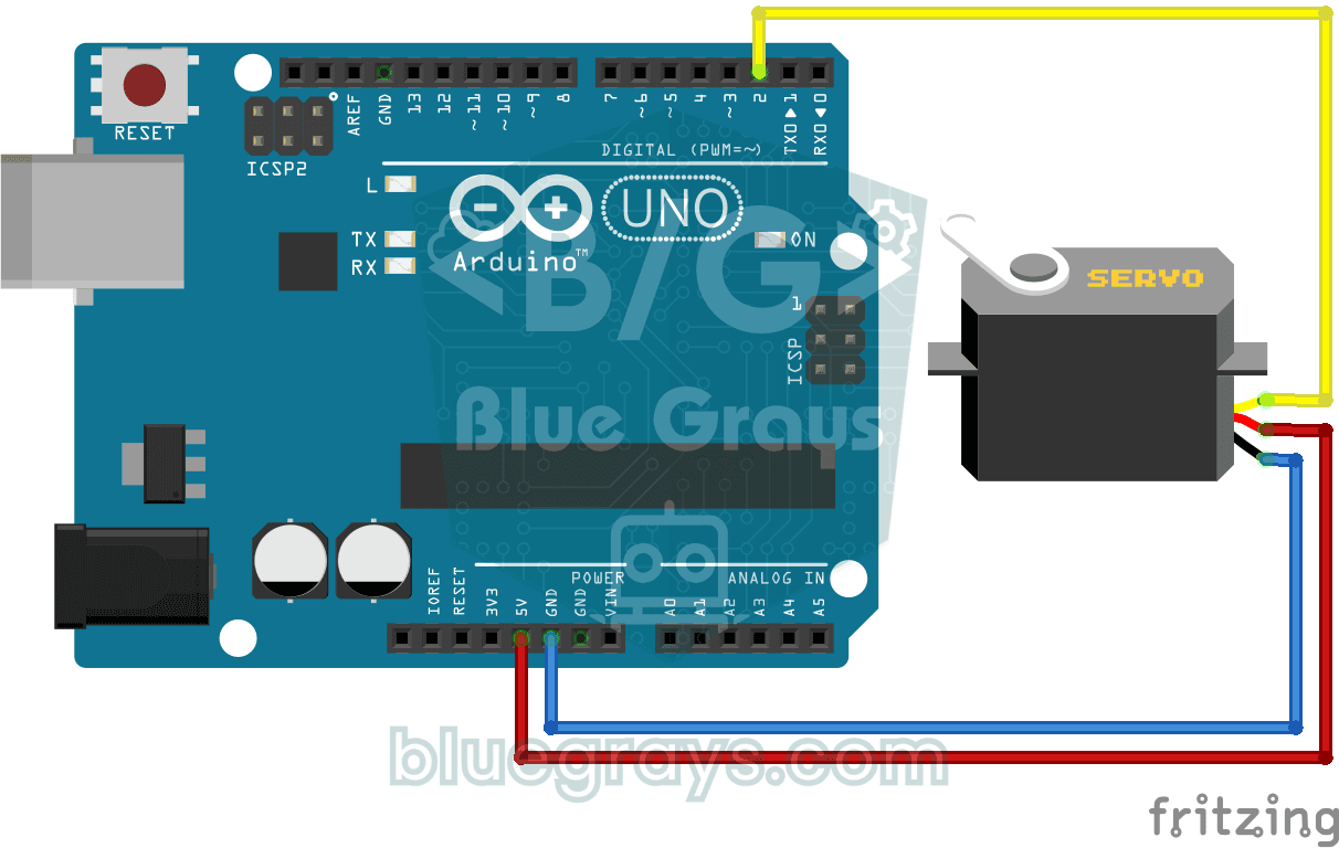
Using a Servo Motor
The arm of a small servo motor turns to three positions in turn: all the way to the start, right to the middle and all the way to the end, waiting two seconds at each stop.
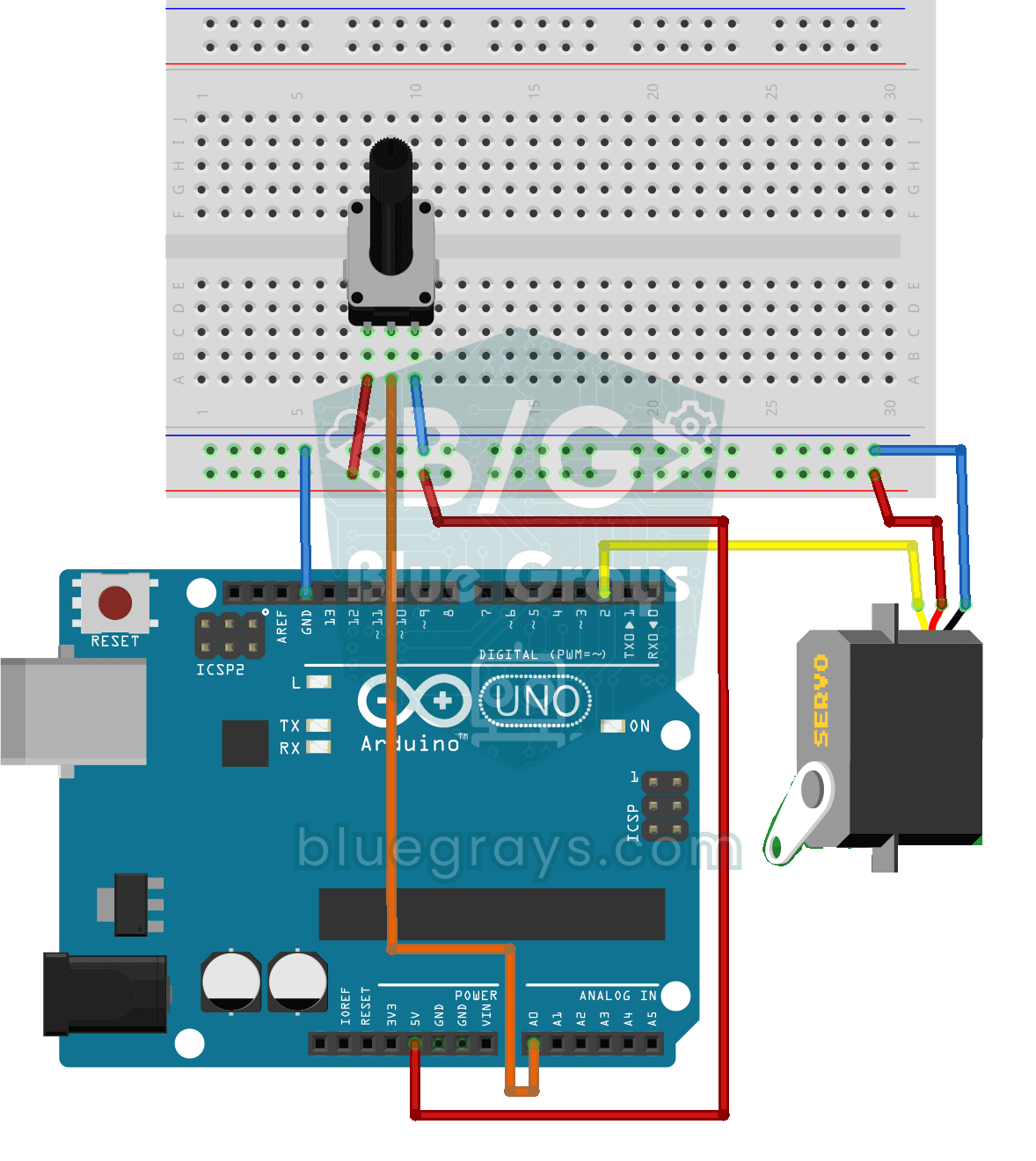
Servo Motor Operation with Potentiometer
As you turn the potentiometer knob, the servo motor's arm turns right along with it: one end of the knob means zero degrees, the other end means half a turn.
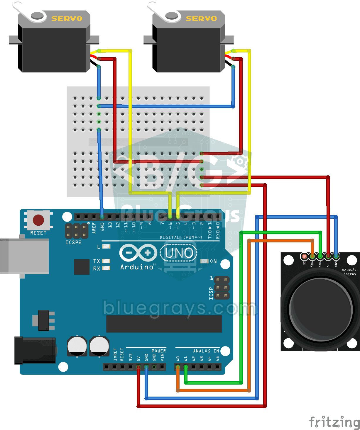
Servo Control with Joystick
Steer two motors with a joystick, just like turning a security camera. Push the stick left or right and the bottom servo motor slowly turns, push it up or down and the top servo tilts up and down…

ESP32 Servo Motor (Potentiometer Control)
In this project, we control an SG90 servo motor using a potentiometer. We adjust the servo angle by mapping the analog value read from the potentiometer to the 0–180-degree range. The ESP32Servo library generates servo signals on suitable output-capable GPIO pins of the ESP32; this project uses GPIO 18. This is a fundamental control method for robotic arms, camera gimbals, and automatic door mechanisms.

ESP32 RFID Door Lock (RC522 + Servo + OLED + Buzzer + LED)
We build a smart door lock with an ESP32, an RC522 RFID module, an SG90 servo, an SSD1306 OLED display, an active buzzer and 2 LEDs. When a card is scanned, its UID is checked against the authorized cards defined in the code; if it matches, the servo unlocks (green LED + 2 short beeps) and locks again after 5 seconds. An unknown card lights the red LED, gives 3 quick beeps and shows its UID on the OLED.

Servo Circle Choreography - Animated Patterns with 32 Servos
A visual animation project driven by 32 servo motors arranged in a circle on an Arduino Mega. The servos are managed in a single array, connected to the Mega's pins 22–53, and perform four motion sequences: a chaotic jitter at random angles, a synchronized sweep, a wave travelling around the circle and a compass needle swinging left and right.

Obstacle Avoidance Robot
How about building a smart vehicle that finds its own way? The Obstacle Avoidance Robot constantly scans its surroundings thanks to the ultrasonic sensor in front of it.