
INA219 Arduino Tutorial: Measure Current, Voltage and Power
How do you connect an INA219 current sensor to Arduino, ESP32 and Pico? 0.1 Ω shunt, 26 V/3.2 A limit, calibration, solar and battery measurement, ACS712 comparison.
The INA219 is the most practical way to measure current, voltage and power at the same time in Arduino projects. This small Texas Instruments chip digitally calculates the current through a shunt resistor placed in series with your circuit, the voltage on the load side, and the power, which is the product of the two. It sends the results over just two I2C wires. Typical modules have a 0.1 Ω shunt, and in that form the sensor can measure a line up to 26 V and currents up to about ±3.2 A in steps of roughly 0.1 mA.
If you want to know how much power a solar panel produces during the day, how many hours an ESP32 project will take to drain its battery, or how much current a motor draws under load, this is exactly the sensor you need. In this post you'll learn step by step how the shunt works, the measurement ranges, the calibration maths, working code for Arduino Uno, ESP32 and Raspberry Pi Pico, and how it differs from the ACS712.
What is the INA219 and how does it work?
The INA219 is built on Ohm's law. A very low-value precision resistor (the shunt) is placed in the current path; as current flows through it, a small voltage drop proportional to the current appears across it. With a 0.1 Ω shunt, 1 A gives 100 mV and 250 mA gives 25 mV (V = I × R). The chip's programmable gain amplifier (PGA) and 12-bit ADC read this millivolt-level voltage and store it in the shunt voltage register in 10 µV steps. The chip also measures the voltage between the load-side end of the shunt (Vin−) and GND at 4 mV resolution; this is called the bus voltage. Once the correct value is written to the calibration register, the INA219 calculates current and power internally, so the microcontroller doesn't have to multiply or divide anything. Because the shunt sits between the positive of the supply and the load, this is called high-side measurement, and the load's ground is left untouched. Current is measured in both directions: current flowing from Vin+ to Vin− is positive, and current in the opposite direction appears negative.
| Feature | Value |
|---|---|
| Chip | Texas Instruments INA219 (A and B versions) |
| Communication | I2C / SMBus, 400 kHz fast mode supported |
| Supply (VCC) | 3.0–5.5 V |
| Measurable bus voltage | 0–26 V (register range set to 16 V or 32 V) |
| Shunt voltage range | ±40, ±80, ±160 or ±320 mV (selected with the PGA) |
| Shunt on the module | 0.1 Ω (marked R100) |
| Maximum current (with 0.1 Ω) | About ±3.2 A |
| ADC | 12-bit, 532 µs conversion time, up to 128 samples of built-in averaging |
| Accuracy | INA219B: max 0.5% error over the full temperature range (1% for the A version) |
| I2C address | 0x40 (0x41, 0x44, 0x45 with the A0/A1 bridges) |
Shunt resistor and measurement range
The maximum current the INA219 can measure is set by the shunt value and the PGA setting: I_max = V_shunt,max / R_shunt. In a narrow range small voltages are read with less error, while a wide range lets you reach larger currents. The power the shunt dissipates is P = I² × R: at 3.2 A, a 0.1 Ω shunt turns about 1 W into heat, and the 320 mV drop across it also reduces the voltage the load receives. For larger currents you can swap the shunt for a smaller one such as 0.01 Ω, but the module's thin copper traces and terminals are usually designed for around 3 A. For very small currents, a 1 Ω shunt makes the step ten times finer: 10 µV / 1 Ω = 10 µA. With the module's 0.1 Ω shunt, the four options are:
| PGA setting | Shunt voltage range | Max current (0.1 Ω) | When to use it |
|---|---|---|---|
| /1 | ±40 mV | ±400 mA | Sensors, microcontroller boards, low-current circuits |
| /2 | ±80 mV | ±800 mA | Short LED strips, a single servo motor |
| /4 | ±160 mV | ±1.6 A | Small DC motors, mini pumps |
| /8 (default) | ±320 mV | ±3.2 A | Solar panels, motors, general use |
INA219 wiring: Arduino Uno, ESP32 and Pico
| INA219 pin | Arduino Uno | ESP32 | Raspberry Pi Pico | Function |
|---|---|---|---|---|
| VCC | 5V | 3V3 | 3V3(OUT), pin 36 | Chip supply |
| GND | GND | GND | GND | Common ground (must also connect to the load's negative) |
| SCL | A5 | GPIO 22 | GP5 (pin 7) | I2C clock line |
| SDA | A4 | GPIO 21 | GP4 (pin 6) | I2C data line |
| Vin+ | Supply positive | Supply positive | Supply positive | Where current enters |
| Vin− | Load positive | Load positive | Load positive | Where current leaves |
Think of the current path as a chain: supply positive, Vin+, shunt, Vin−, load positive, load negative and finally supply negative. The INA219 joins this chain in series, just like an ammeter. The supply negative, the load negative and the module's GND pin must all be connected together; otherwise the bus voltage reading is meaningless even if the current looks right (see the common ground post for details). On the Uno you can also use the SDA/SCL pins near the top corner of the board instead of A4/A5; they're the same lines. Most modules come with I2C pull-up resistors, so no extra resistors are needed. On the ESP32 and Pico, if you power the module from 3V3, those pull-ups also pull to 3.3 V and your pins stay safe.
Step by step: your first measurement with Arduino Uno
- Open the Library Manager in the Arduino IDE, search for the Adafruit INA219 library, and accept the Adafruit BusIO dependency when prompted. If you're new to installing libraries, see adding libraries.
- Connect the module's VCC, GND, SDA and SCL pins to the Uno as in the table.
- Choose the load you want to measure: for example a red LED with a 220 Ω resistor on a 9 V battery, or a small DC motor. Connect the battery's positive to Vin+ and Vin− to the load's positive.
- Connect the battery's negative to both the load's negative and the INA219's GND pin, so the Uno, battery and load share a common ground.
- Upload the code, open the Serial Monitor at 115200 baud, and compare the current you read with a multimeter connected in series.
1#include <Wire.h>
2#include <Adafruit_INA219.h>
3
4Adafruit_INA219 ina219;                 // varsayılan adres 0x40 / default address 0x40
5
6void setup() {
7  Serial.begin(115200);
8  if (!ina219.begin()) {                // sensörü ve I2C'yi başlat / start sensor and I2C
9    Serial.println(F("INA219 bulunamadi / INA219 not found"));
10    while (1) { delay(10); }
11  }
12  // ina219.setCalibration_32V_1A();    // daha ince adım / finer steps
13  // ina219.setCalibration_16V_400mA(); // küçük akımlar / small currents
14  Serial.println(F("INA219 hazir / ready"));
15}
16
17void loop() {
18  float shunt_mV   = ina219.getShuntVoltage_mV();  // şönt üzerindeki gerilim / voltage across the shunt
19  float bus_V      = ina219.getBusVoltage_V();     // Vin- ile GND arası / Vin- to GND
20  float current_mA = ina219.getCurrent_mA();       // akım / current
21  float power_mW   = ina219.getPower_mW();         // güç / power
22  float source_V   = bus_V + shunt_mV / 1000.0;    // kaynak gerilimi / source voltage
23
24  Serial.print(F("Kaynak: ")); Serial.print(source_V, 2);   Serial.print(F(" V  "));
25  Serial.print(F("Yuk: "));    Serial.print(bus_V, 2);      Serial.print(F(" V  "));
26  Serial.print(F("Sont: "));   Serial.print(shunt_mV, 2);   Serial.print(F(" mV  "));
27  Serial.print(F("Akim: "));   Serial.print(current_mA, 1); Serial.print(F(" mA  "));
28  Serial.print(F("Guc: "));    Serial.print(power_mW, 0);   Serial.println(F(" mW"));
29  delay(1000);
30}| Function | Returned value |
|---|---|
| ina219.begin() | Returns true if the sensor is found; also starts the I2C bus |
| getShuntVoltage_mV() | Voltage across the shunt (mV) |
| getBusVoltage_V() | Voltage between Vin− and GND, i.e. the voltage the load sees (V) |
| getCurrent_mA() | Current calculated from the calibration (mA), negative in the reverse direction |
| getPower_mW() | Product of current and bus voltage (mW) |
| bus_V + shunt_mV / 1000 | The source's own voltage before the shunt (V) |
In the example with a 9 V battery and a red LED with a 220 Ω resistor, the current comes out at around (9 − 2) / 220 ≈ 32 mA; about 3.2 mV drops across the shunt and the circuit's total power is 9 V × 32 mA ≈ 290 mW. As the battery tires you can watch live as the voltage falls to 8 V and the current drops with it. Seeing small values like 0.1–0.5 mA with no load connected is normal; they come from a small offset at the chip's input and don't mean your measurement is broken.
Calibration: the key to accurate measurement
When the INA219 powers up, the calibration register is zero; so although you can read the shunt and bus voltages immediately, the current and power registers stay at zero. The calibration value comes from two formulas in the datasheet: first calculate Current_LSB = expected maximum current / 32768 and round it to a convenient number, then find Cal = 0.04096 / (Current_LSB × R_shunt). The power register's step is always 20 times Current_LSB. With the module's 0.1 Ω shunt and 3.2 A, Current_LSB = 3.2 / 32768 ≈ 97.7 µA, which rounds to 100 µA; Cal = 0.04096 / (0.0001 × 0.1) = 4096 and the power step is 2 mW. The Adafruit library offers three ready-made profiles that do this calculation for you:
| Function | Bus range | Shunt range | Max current | Current step |
|---|---|---|---|---|
| setCalibration_32V_2A() (default) | 32 V | ±320 mV | ≈3.2 A | 0.1 mA |
| setCalibration_32V_1A() | 32 V | ±320 mV | ≈1.3 A | 0.04 mA |
| setCalibration_16V_400mA() | 16 V | ±40 mV | ≈400 mA | 0.05 mA |
The "32 V" in the table is only the register range; the chip's real limit is still 26 V. If you've changed the shunt, the ready-made profiles will give wrong results. The easiest fix is to calculate the current yourself: current (mA) = getShuntVoltage_mV() / R_shunt (Ω). For example, if you read 15 mV with a 1 Ω shunt, the current is 15 mA. To fine-tune against a reference you trust, use the datasheet's correction formula: Cal_new = Cal × (current shown by the multimeter / current shown by the INA219). If the multimeter shows 500 mA and the INA219 shows 495 mA, you write 4096 × 500 / 495 ≈ 4137. Because the calibration register resets when power is lost, the Adafruit library rewrites the value before each current reading; if you write your own code, you should also resend the calibration every time you start the sensor. You'll see writing directly to the register in the Pico section.
Battery consumption with the ESP32: an mAh and mWh counter
To know how long a battery will last, total consumption matters more than instantaneous current. Total charge is the accumulation of current over time: multiply the current (mA) by the elapsed time (hours) at each measurement and add it up to get mAh, and do the same with power to get mWh. The code below uses the ESP32's default I2C pins (SDA 21, SCL 22), selects the 32V_1A profile for finer steps, and updates the totals every half second. Because it uses no version-dependent functions, it compiles unchanged with ESP32 Arduino core 2.x and 3.x.
1#include <Wire.h>
2#include <Adafruit_INA219.h>
3
4Adafruit_INA219 ina219(0x40);
5
6float totalmAh = 0.0;              // toplam yük / total charge
7float totalmWh = 0.0;              // toplam enerji / total energy
8unsigned long lastMs = 0;
9
10void setup() {
11  Serial.begin(115200);
12  Wire.begin(21, 22);              // SDA, SCL
13  if (!ina219.begin(&Wire)) {
14    Serial.println("INA219 bulunamadi / not found");
15    while (true) { delay(10); }
16  }
17  ina219.setCalibration_32V_1A();  // 1,3 A'e kadar, 0,04 mA adım / up to 1.3 A, 0.04 mA steps
18  lastMs = millis();
19}
20
21void loop() {
22  unsigned long now = millis();
23  if (now - lastMs >= 500) {
24    float hours = (now - lastMs) / 3600000.0;   // geçen süre (saat) / elapsed time (hours)
25    lastMs = now;
26
27    float busV      = ina219.getBusVoltage_V();
28    float currentmA = ina219.getCurrent_mA();
29    float powermW   = ina219.getPower_mW();
30
31    totalmAh += currentmA * hours;   // mA x saat = mAh / mA x hours = mAh
32    totalmWh += powermW * hours;     // mW x saat = mWh / mW x hours = mWh
33
34    Serial.printf("%.2f V  %.1f mA  %.0f mW  |  %.3f mAh  %.2f mWh\n",
35                  busV, currentmA, powermW, totalmAh, totalmWh);
36  }
37}
For example, if a sensor node draws 45 mA on average, a 2500 mAh 18650 cell theoretically lasts 2500 / 45 ≈ 55 hours; in practice, because of conversion losses and not draining the cell completely, it's realistic to count on 70–80% of that. You can do this calculation quickly with the battery life calculator. Be careful with deep sleep tests: with a 0.1 Ω shunt the real step is about 0.1 mA, so a sleep current at the microamp level looks like zero. Most development boards draw a few mA even asleep because of the USB-serial chip and regulator, and the INA219 shows that easily. To see the roughly 10 µA sleep current of a bare ESP32 module you need a 1–10 Ω shunt; the maximum current then falls to between 320 mA and 32 mA, so you can't measure the awake current with the same setup.
Raspberry Pi Pico and MicroPython: the INA219 through its registers
In MicroPython, driving the INA219 directly through its registers without any library is both easy and very instructive. The value 0x399F we write to the configuration register (0x00) selects the 32 V range, /8 PGA, 12-bit resolution and continuous measurement mode; this is also the chip's default at power-up. Then 4096 is written to the calibration register (0x05). The shunt voltage (0x01) and current (0x04) are signed 16-bit numbers; for the bus voltage register (0x02), the lowest 3 bits are dropped and the value is multiplied by 4 mV. If you save the code in Thonny as main.py, the Pico starts measuring at every power-up. If you change the shunt, you only need to update R_SHUNT and CURRENT_LSB; Cal is calculated automatically. If you're new to MicroPython, the MicroPython basics post is a good place to start.
1from machine import Pin, I2C
2import time
3
4ADDR = 0x40                       # A0, A1 boşta / A0, A1 open
5R_SHUNT = 0.1                     # ohm, modüldeki R100 / the module's R100
6CURRENT_LSB = 0.0001              # 0,1 mA/bit
7CAL = round(0.04096 / (CURRENT_LSB * R_SHUNT))   # = 4096
8
9i2c = I2C(0, sda=Pin(4), scl=Pin(5), freq=400000)
10
11def write_reg(reg, value):
12    i2c.writeto_mem(ADDR, reg, bytes([(value >> 8) & 0xFF, value & 0xFF]))
13
14def read_reg(reg, signed=False):
15    d = i2c.readfrom_mem(ADDR, reg, 2)
16    v = (d[0] << 8) | d[1]
17    if signed and v > 32767:      # ikiye tümleyen / two's complement
18        v -= 65536
19    return v
20
21print("Bulunan / found:", [hex(a) for a in i2c.scan()])
22write_reg(0x00, 0x399F)   # 32 V, PGA /8, 12 bit, sürekli / 32 V, PGA /8, 12-bit, continuous
23write_reg(0x05, CAL)      # kalibrasyon / calibration
24
25while True:
26    shunt_mv = read_reg(0x01, True) * 0.01               # 10 uV/bit
27    bus_v = (read_reg(0x02) >> 3) * 0.004                # 4 mV/bit
28    current_ma = read_reg(0x04, True) * CURRENT_LSB * 1000
29    power_mw = read_reg(0x03) * CURRENT_LSB * 20 * 1000  # güç adımı = 20 x LSB / power step = 20 x LSB
30    print("{:.2f} V  {:.2f} mV  {:.1f} mA  {:.0f} mW".format(bus_v, shunt_mv, current_ma, power_mw))
31    time.sleep(1)
Measuring solar panels and battery charging
In solar panel projects, the INA219 is connected between the panel's positive and the charging circuit or load, and shows the real power the panel is producing at that moment. Remember that you only see the rated power under a suitable load: with no load the current is zero and the voltage is the open-circuit voltage (Voc). A small 6 V 2 W panel gives about 330 mA in full sun; on a cloudy day this can drop to a tenth. By logging measurements once a minute you can calculate daily energy production in Wh, see the effect of panel angle, or compare a fixed panel with a solar tracking system. Panels sold as "12 V" have an open-circuit voltage of around 21–22 V; that's still safe for the INA219, but if you connect two panels in series you exceed the 26 V limit. In systems with a panel and a battery, if you place the INA219 between the battery and the circuit with Vin+ towards the battery and Vin− towards the circuit, you benefit from bidirectional measurement: current appears positive while the battery powers the circuit and negative while it charges. That way you can also see how much current a charging module like the TP4056 actually delivers to the battery.
INA219 or ACS712?
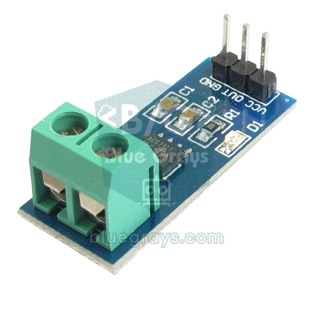
| Feature | INA219 | ACS712 (5 A) |
|---|---|---|
| Measurement principle | Shunt resistor + ADC | Hall effect |
| Output | Digital (I2C) | Analog voltage (VCC/2 at zero current) |
| What it measures | Current, voltage and power | Current only |
| Current type | DC only | AC and DC |
| Range | ±3.2 A (with 0.1 Ω shunt), up to 26 V | ±5 A (20 A and 30 A versions also exist) |
| Resolution | About 0.1 mA | 185 mV/A; about 26 mA per step with the Uno's ADC |
| Isolation | None | Yes (2.1 kV RMS) |
| Supply | 3.0–5.5 V | 5 V |
In short, for DC circuits under a few amps, for battery and solar panel measurement, and for low-current microcontroller projects, the INA219 is far more accurate and practical; it also uses no analog pin and up to four sensors can share the same I2C bus. Monitoring AC current on the mains side, going above 5 A, or wanting electrical isolation between the measured circuit and the microcontroller is the ACS712's territory; see the ACS712 current sensor post for details. If you need voltages above 26 V or higher resolution, the INA226 (36 V, 16-bit) from the same family is the better choice, and the INA3221 puts three channels on one chip. If you want to see the measured voltage over a wider range, the voltage divider method in the Arduino voltmeter post is also a good complement.
Project ideas with the INA219
- USB power meter: Route the 5 V line of a USB cable through the INA219 and show how many mA a phone charger or Arduino board draws on an OLED display.
- Solar energy logger: Measure the panel's power once a minute with an ESP32, save it to an SD card and calculate daily Wh production.
- Battery capacity tester: Discharge an 18650 cell through a fixed-resistor load down to 3.0 V and find its real capacity from the accumulated mAh (see what is mAh).
- Motor stall alarm: Stop the DC motor when its current doubles; ideal for detecting a jammed wheel on robot cars.
- Pump dry-run protection: When the water runs out, a mini pump's current drops noticeably; detect the drop and switch the pump off to extend its life.
- Lab power supply display: Show the output voltage, current and power of an adjustable supply live on an I2C LCD.
Common mistakes and how to fix them
| Symptom | Likely cause | Fix |
|---|---|---|
| "INA219 not found" message | SDA/SCL swapped, VCC not connected or a different address | Check the wires, find the address with an I2C scanner (0x40–0x45) |
| Current reads negative | Vin+ and Vin− are swapped | Connect the supply to Vin+ and the load to Vin−, or flip the sign in software |
| Current is right, voltage is 0 or nonsense | The load's negative and the INA219's GND are not common | Join the GNDs of the supply, load and module |
| Current always 0 | No load connected, module wired in parallel or current below the step size | Check the series connection; use a larger shunt for very small currents |
| Value stuck around 3.2 A | Shunt voltage range exceeded | Reduce the load or use a smaller shunt and calculate the current yourself |
| Readings keep jumping | PWM-driven motor or LED, wire noise | Take an average, increase the internal sample count, apply a software filter |
| Module got hot or burned out | Parallel connection (short circuit) or current above 3 A | Always wire the module in series and use a fuse on the line |
With one small module, the INA219 gives your project a voltmeter, an ammeter and a wattmeter all at once; behind many ideas, from solar panels and battery life to motor protection and USB power meters, lies accurate measurement. In the BlueGrays app you'll find projects such as a digital voltmeter with an LCD, ESP32 deep sleep, a temperature logger and smart irrigation, with step-by-step circuit diagrams and code, and you can add the INA219 to them and start measuring their consumption right away.
Frequently asked questions
How many amps can the INA219 measure at most?
With the 0.1 Ω shunt on ready-made modules, the INA219 measures up to about ±3.2 A, because the chip's shunt voltage limit is ±320 mV. If you replace the shunt with a smaller resistor such as 0.01 Ω, the theoretical range rises to 32 A; but since the module's copper traces and terminals aren't built for that current, you'd need to move the shunt and thick wires off the board.
Can the INA219 measure AC current?
No. The INA219 is designed for DC circuits and the voltage at its terminals must stay within 0–26 V; connecting it to mains would both destroy the chip and be life-threatening. For AC current, isolated Hall effect sensors such as the ACS712 or current transformers such as the SCT-013 are used.
How do you change the INA219's I2C address?
The A0 and A1 solder bridges on the module set the address: 0x40 with both open, 0x41 with only A0 closed, 0x44 with only A1 closed and 0x45 with both closed. In code, just specify the address as Adafruit_INA219 ina219(0x41);. That way you can connect four different INA219s to the same I2C bus.
What is the difference between the INA219 and the INA226?
The INA226 is the more advanced member of the same family: the bus voltage goes up to 36 V and its 16-bit ADC gives much higher resolution. The INA219 is cheaper and more common, with very wide Arduino library support. For hobby projects under 26 V and a few amps, the INA219 is more than enough.
Does the INA219 work at 3.3 V?
Yes, the INA219's supply range is 3.0–5.5 V. On the ESP32 and Raspberry Pi Pico, powering the module from the 3V3 pin keeps the I2C lines at 3.3 V too. The supply voltage doesn't limit the line being measured; an INA219 powered at 3.3 V can still measure a line up to 26 V.
Why does the INA219 show a small current even with no load?
The chip's shunt input has an offset of a few tens of microvolts; with a 0.1 Ω shunt this means a small reading of 0.1–0.5 mA. You can remove this error by recording the value read with no load and subtracting it from later measurements, or by averaging several readings.
Projects to build after reading this
See all projects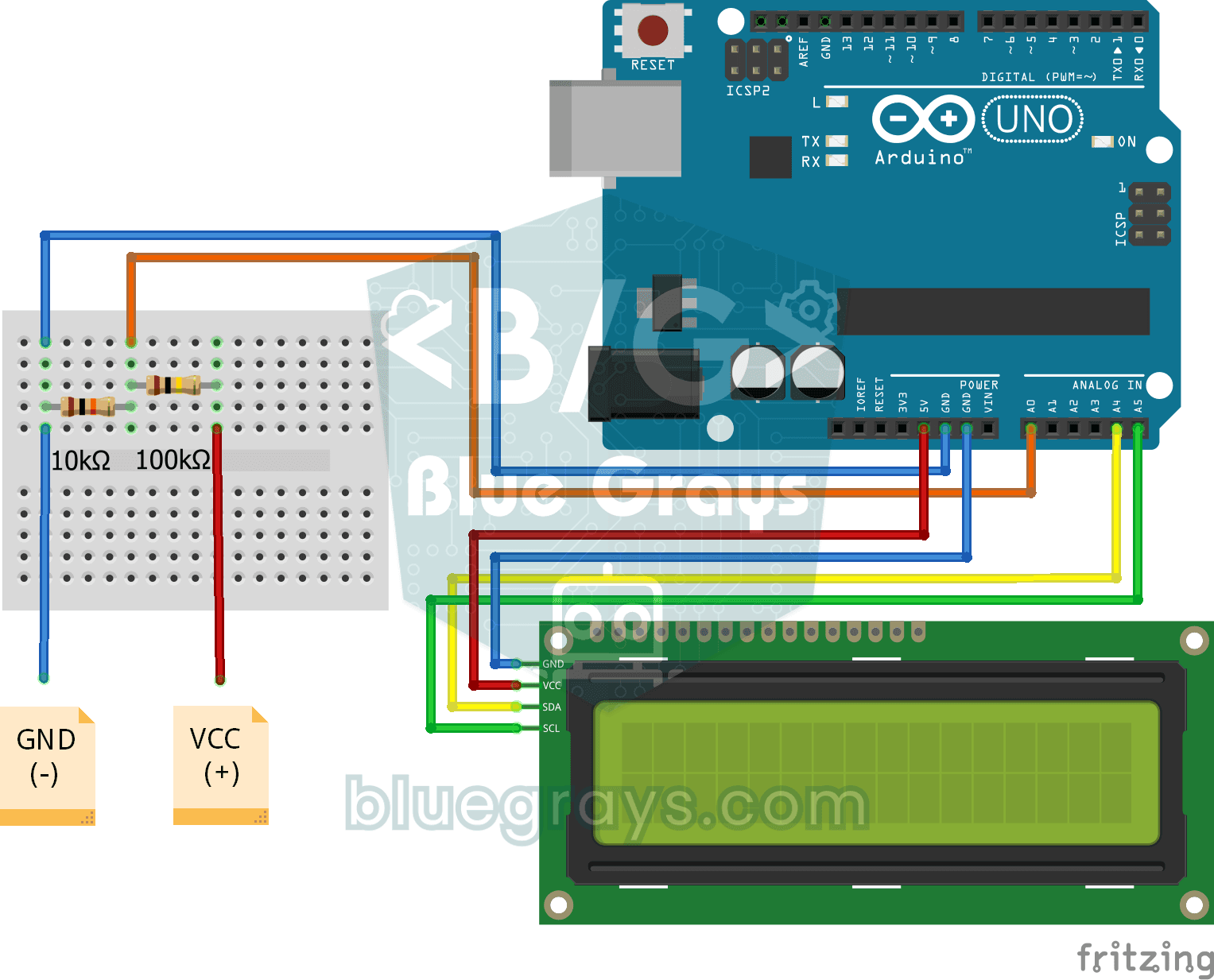
Digital Voltmeter with LCD Display
Find out how much voltage a battery or power adapter gives with a meter you built yourself.

ESP32 Deep Sleep — Battery Saving (OLED + RTC RAM Counter)
The ESP32's Deep Sleep mode shuts down the CPU and most peripherals, cutting current draw to about 10µA, which is vital for battery-powered IoT devices. This project uses three wake-up sources: a timer (15 s), an external pin (EXT0, the button on GPIO 33) and a touch pin (T0/GPIO 4). Counters marked with RTC_DATA_ATTR survive deep sleep.
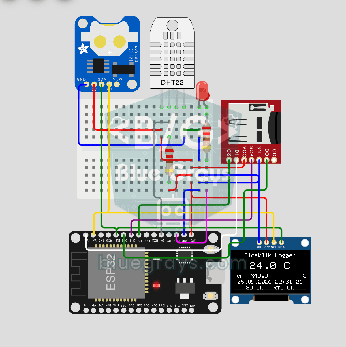
ESP32 Temperature Data Logger (DHT22 + DS1307 RTC + microSD + OLED)
Build a timed temperature and humidity logger with the ESP32! A DHT22 sensor reads temperature and humidity once a minute, and each reading is saved to a microSD card in CSV format with a real-time stamp from the DS1307 RTC module. The OLED display shows the latest temperature, humidity, timestamp and total number of records live, in large text.
Using LCD Screen with I2C
Give your Arduino its own screen and make it write its first message. The two-line LCD screen hooks up with just a few wires; a greeting appears on the top line, then a second message on the bottom…

ESP32 I2C LCD Display (16x2)
In this project we connect a 16x2 character LCD to the ESP32 over I2C and display text. With I2C, just 2 data pins (SDA and SCL) control the screen, instead of the 6+ pins a classic parallel connection wastes. The code prints a fixed message on the first line and a counter that goes up every second on the second. At startup an I2C scanner also prints the display's address to the Serial Monitor (usually 0x27 or 0x3F).

Smart Irrigation Station
A gardener that waters your plants on its own, so they don't dry out while you're on vacation.

ESP32 Smart Lighting (PIR + LDR + Relay + OLED)
With an ESP32, a PIR motion sensor, an LDR light sensor and a relay module, we turn your hallway, bathroom or pantry into smart lighting. If the room is already bright, the light stays off even when there is motion, so it never wastes energy during the day. The light stays on for 30 seconds, and the time extends automatically while motion continues.