
Arduino Voltmeter: Measure 0–25 V with an LCD and Calibration
How to build an Arduino voltmeter: measure 0–25 V with a divider, pick resistors, add zener protection, calibrate, use an LCD, an INA219 and a battery tester.
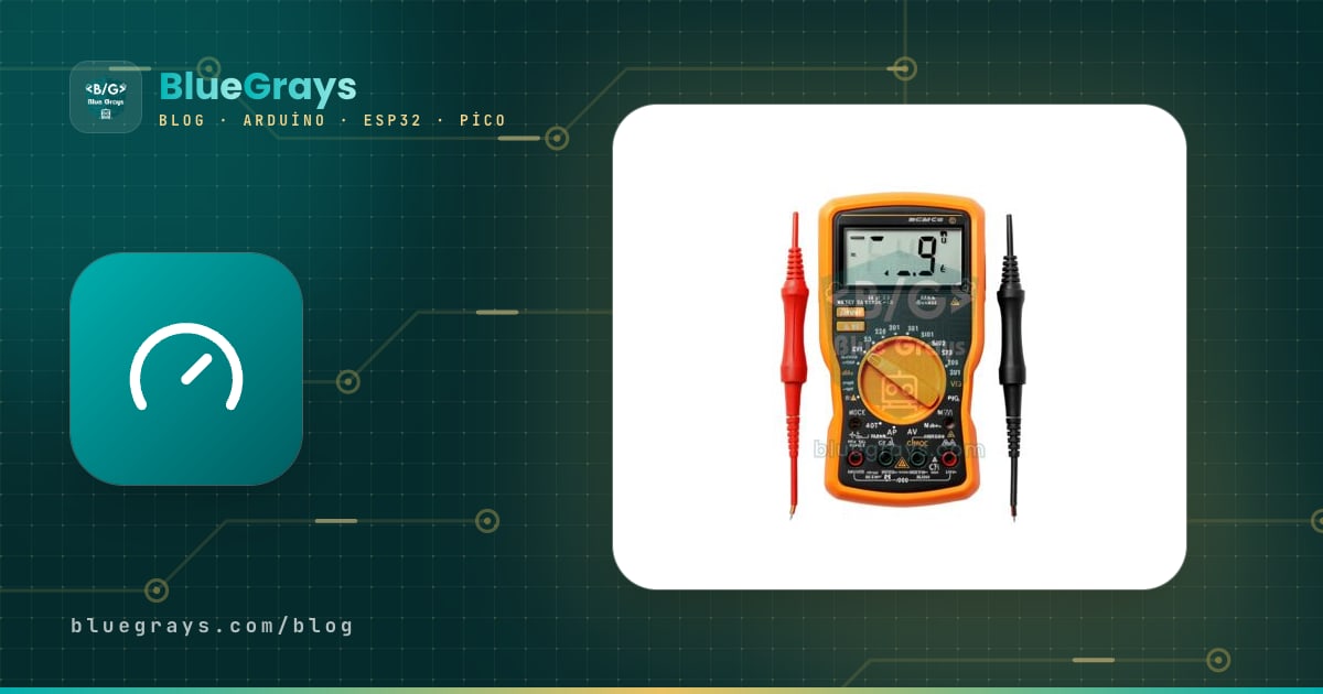
An Arduino voltmeter is a measuring instrument you can build in an evening: two resistors, one analog input and a few lines of code are enough to measure 0–25 V accurately and show it on a display. Arduino's analog inputs can read at most 5 V, so to measure a higher voltage you first scale it down with a voltage divider and then scale it back up in code by the same ratio. Battery monitors, power supply readouts, solar panel loggers and battery testers all rely on this one idea.
In this guide you'll learn step by step how to pick resistor values for a given range, how a zener and series resistor protect the analog input from overvoltage, how the ready-made 0–25 V voltage sensor module works, and how setting the reference voltage and calibrating bring your readings close to a multimeter's. Then you'll show the value on an I2C LCD, build the same voltmeter on an ESP32 and a Raspberry Pi Pico, add current sensing with an INA219 to turn it into a wattmeter, and finally make a tester that measures a battery's real capacity in mAh.
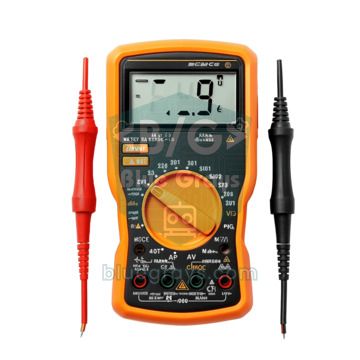
How does an Arduino voltmeter work?
Arduino doesn't know voltage directly; its ADC (analog-to-digital converter) compares the voltage on the analog input with a reference voltage and returns the result as an integer. The Arduino Uno's ADC is 10-bit: it reads 0 for 0 V and 1023 for the reference voltage (5 V by default). The voltage at the pin is Vpin = reading × Vref / 1024. If there's a voltage divider at the input, the voltage you're actually measuring is Vin = Vpin × (R1 + R2) / R2. So the accuracy of the whole voltmeter depends on three things: the real value of Vref, the ratio of the two resistors and the ADC's own error.
| Board | ADC | Reference | 1 step at the pin | 1 step with a 0–25 V divider |
|---|---|---|---|---|
| Arduino Uno, Nano, Pro Mini | 10-bit (0–1023) | 5 V (AVcc) | 4.88 mV | 24.4 mV (30 kΩ + 7.5 kΩ) |
| ESP32 | 12-bit (0–4095) | About 3.3 V (11 dB attenuation) | About 0.8 mV | About 9 mV (100 kΩ + 10 kΩ) |
| Raspberry Pi Pico | 12-bit (0–65535 via read_u16) | 3.3 V (ADC_VREF) | 0.81 mV | 8.9 mV (100 kΩ + 10 kΩ) |
The voltage divider and choosing resistors for 0–25 V
The voltage you're measuring enters through the top resistor R1, the midpoint where the two resistors meet goes to the analog pin, and the bottom resistor R2 goes to GND. When choosing resistors, first decide the highest voltage, then pick a ratio that leaves the pin a little below the reference at that voltage, for example about 4.5 V on an Uno. The 30 kΩ and 7.5 kΩ pair used in ready-made modules divides by exactly 5: 25 V at the input gives 5.00 V at the pin. Don't pick values at random either: if the total resistance is too low the divider wastes current from the source you're measuring, and if it's too high the sampling capacitor inside the ADC can't charge and the reading drifts. The ATmega328P datasheet recommends that the source driving an analog input be no more than 10 kΩ; for a divider that source resistance is R1 and R2 in parallel (6 kΩ for 30 kΩ and 7.5 kΩ). You'll find the formula in detail, plus loading effects, in the voltage divider article.
| Range | Arduino Uno (5 V): R1 + R2 | Pin at full range | ESP32 / Pico (3.3 V): R1 + R2 | Pin at full range |
|---|---|---|---|---|
| 0–10 V | 12 kΩ + 10 kΩ | 4.55 V | 33 kΩ + 10 kΩ | 2.33 V |
| 0–25 V | 30 kΩ + 7.5 kΩ (ready-made module) | 5.00 V | 100 kΩ + 10 kΩ | 2.27 V |
| 0–30 V | 56 kΩ + 10 kΩ | 4.55 V | 120 kΩ + 10 kΩ | 2.31 V |
| 0–50 V | 100 kΩ + 10 kΩ | 4.55 V | 220 kΩ + 10 kΩ | 2.17 V |
Protection: zener diode, series resistor and capacitor
Even with a correctly calculated divider, a wrong probe, a spike on the power supply or accidentally touching 48 V instead of 25 V can push the pin above 5 V. The ATmega328P's pins tolerate at most the supply plus 0.5 V. Inside the pin there are protection diodes to 5 V and GND, but they only handle small currents. The good news is that the divider's top resistor already limits the current. With a 30 kΩ R1, even touching 50 V lets at most about 1.5 mA flow into the pin. To reduce that current further and absorb the excess voltage safely, you can add the following layers.
- Series resistor: Put a 4.7–10 kΩ resistor between the divider's midpoint and the analog pin. During overvoltage, the current into the pin's internal diodes drops to the microamp range.
- 100 nF capacitor: Connect it between the analog pin and GND. It makes up for the higher source resistance caused by the series resistor, because the ADC takes the charge it needs while sampling from this capacitor. It also filters noise and short spikes.
- 5.1 V zener diode: Connect a zener such as the 1N4733A or BZX55C5V1 with its cathode to the pin and its anode to GND. When the voltage tries to rise above 5.1 V, the zener conducts and dumps the excess to GND.
- Watch the zener leakage: A zener starts drawing a small current a little below its breakdown voltage, and with a high-resistance divider that current pulls the reading down. If you use a zener, keep the pin's maximum around 4 V, or use a Schottky diode (BAT85) from the pin to the 5 V rail instead.
- Reverse polarity: If you connect the probes backwards, a negative voltage reaches the pin. The series resistor limits the current; for extra safety you can add a second Schottky diode with its anode to GND and its cathode to the pin.
The ready-made voltage sensor module (0–25 V)
If you'd rather not solder, you can use the small red or blue module sold as a "voltage sensor". There's nothing magic inside: just a divider made of exactly a 30 kΩ and a 7.5 kΩ resistor, a screw terminal and a three-pin header. Because the ratio is 5, you can measure 0–25 V with a 5 V Arduino, but only up to 16.5 V with a 3.3 V board. On a 3.3 V board, touching 25 V puts 5 V on the pin and damages it, so for the ESP32 and Pico it's safer to build your own divider from the table above. The module has no protection diode, so the zener or Schottky measures from the previous section apply here too.
| Module pin | Function | Arduino Uno | ESP32 (your own divider) | Raspberry Pi Pico (your own divider) |
|---|---|---|---|---|
| VCC (screw terminal) | Positive of the source to measure | Source + | Top end of R1 | Top end of R1 |
| GND (screw terminal) | Negative of the source to measure | Source − | Source − and GND | Source − and GND |
| S | Divided signal | A0 | GPIO 34 (ADC1) | GP26 (ADC0, pin 31) |
| + | Not connected on most modules | Leave unconnected | - | - |
| − | Module GND | GND | GND | GND (e.g. pin 33) |
Step by step: your first Arduino voltmeter
- Connect the module's S pin to A0 and its − pin to GND. If you're building your own divider, put the 30 kΩ on the source side and the 7.5 kΩ on the GND side, and run the midpoint to A0.
- Plug the Arduino into USB, measure between the 5V pin and GND with a multimeter and note the value. USB voltage is often anywhere between 4.7 and 5.1 V.
- Enter the value you measured in the VREF constant in the code below and upload it.
- Connect the source you want to measure to the module's screw terminal: positive to VCC, negative to GND. A 9 V battery or an adjustable bench supply is ideal for a first test.
- Open the Serial Monitor at 9600 baud. Read the voltage, and at the same time measure the source with your multimeter and compare the two values.
1// Arduino voltmetre: 0-25 V gerilim sensörü modülü / Arduino voltmeter: 0-25 V voltage sensor module
2// Modül S -> A0, modül - -> GND / module S -> A0, module - -> GND
3// Ölçülen kaynak modülün VCC ve GND klemensine / measured source goes to the module's VCC and GND terminals
4const int SENSE_PIN = A0;
5const float VREF = 5.00;       // 5V pininde ölçtüğün gerilim / voltage you measured on the 5V pin
6const float R1 = 30000.0;      // üst direnç (ohm) / top resistor (ohms)
7const float R2 = 7500.0;       // alt direnç (ohm) / bottom resistor (ohms)
8const float CAL = 1.000;       // kalibrasyon: gerçek / okunan / calibration: real / measured
9const int SAMPLES = 32;        // ortalama için örnek sayısı / samples to average
10
11float readVoltage() {
12  analogRead(SENSE_PIN);                    // ilk okumayı at / discard the first reading
13  unsigned long sum = 0;
14  for (int i = 0; i < SAMPLES; i++) {
15    sum += analogRead(SENSE_PIN);
16    delayMicroseconds(500);
17  }
18  float adc = (float)sum / SAMPLES;         // 0-1023 arası ortalama / average between 0 and 1023
19  float vPin = adc * VREF / 1024.0;         // pindeki gerilim / voltage at the pin
20  return vPin * (R1 + R2) / R2 * CAL;       // bölücüden önceki gerilim / voltage before the divider
21}
22
23void setup() {
24  Serial.begin(9600);
25}
26
27void loop() {
28  float v = readVoltage();
29  if (v < 0.05) v = 0.0;                    // boşta gürültüyü sıfırla / zero the noise when idle
30  Serial.print(F("Gerilim / Voltage: "));
31  Serial.print(v, 2);
32  Serial.println(F(" V"));
33  delay(500);
34}
The code averages 32 readings each time, so the ADC's ±1-step jitter largely disappears and the last digit settles down. The first reading is discarded because the ADC's sampling capacitor still holds charge from the previous channel. Rounding anything below 0.05 V to zero stops random values such as 0.02–0.04 V from appearing when nothing is connected. Remember that the resolution is 24.4 mV: even though you see two decimals, the last digit moves in steps of 0.02–0.03 V. If you need finer resolution, narrow the range; with a 0–10 V divider one step drops to 10.7 mV.
Reference voltage and calibration
People often say Arduino voltmeters "measure wrong", but the real source of the error is usually the reference. If the code says 5.00 V while the board gets 4.80 V from USB, every reading is 4% high: a 12.00 V battery shows as 12.50 V. This voltage changes from a desktop to a laptop and from one USB cable to another, and when you power the board from an external adapter its regulator takes over and the value is different again. There are three ways to fix this: measure the 5V pin and write it in the code, use a fixed internal reference, or recalculate the board's own supply voltage at every measurement.
| Method | Code | Advantage | Watch out for |
|---|---|---|---|
| Default (AVcc) | analogReference(DEFAULT) | No setup, full 0–5 V range | Whatever the supply does, the reading does too |
| Internal 1.1 V reference | analogReference(INTERNAL) | Stable and independent of the supply | Varies from 1.0 to 1.2 V between boards; the divider ratio must be about 23 (e.g. 220 kΩ + 10 kΩ) |
| External reference (AREF) | analogReference(EXTERNAL) | Best accuracy with a precision reference such as the LM4040 | This line must run before you apply a voltage to AREF, or it shorts against the internal reference |
| Supply measurement (readVcc) | The code below | No extra parts, stays accurate when USB or the battery changes | Only works on AVR boards (Uno, Nano, Pro Mini); calibrate the 1.1 V value once |
1// Kendi besleme gerilimini ölçen voltmetre (ATmega328P: Uno, Nano, Pro Mini)
2// Voltmeter that measures its own supply (ATmega328P: Uno, Nano, Pro Mini)
3const int SENSE_PIN = A0;
4const float R1 = 30000.0;      // üst direnç / top resistor
5const float R2 = 7500.0;       // alt direnç / bottom resistor
6long bandgapMv = 1100;         // iç referans (mV), kalibrasyonla düzelt / internal reference (mV), fix by calibration
7
8long readVccMv() {
9  // Referans AVcc, ölçülen kanal iç 1,1 V / reference AVcc, measured channel is the internal 1.1 V
10  ADMUX = _BV(REFS0) | _BV(MUX3) | _BV(MUX2) | _BV(MUX1);
11  delay(2);                                  // referans otursun / let the reference settle
12  ADCSRA |= _BV(ADSC);                       // dönüşümü başlat / start a conversion
13  while (bit_is_set(ADCSRA, ADSC)) {}        // bitmesini bekle / wait until it finishes
14  unsigned int raw = ADCW;                   // 10 bit sonuç / 10-bit result
15  return bandgapMv * 1024L / raw;            // Vcc = 1,1 V x 1024 / okunan / Vcc = 1.1 V x 1024 / reading
16}
17
18float readVoltage(float vcc) {
19  analogRead(SENSE_PIN);                     // kanal değişti, ilk okumayı at / channel changed, discard first
20  unsigned long sum = 0;
21  for (int i = 0; i < 32; i++) sum += analogRead(SENSE_PIN);
22  float vPin = (sum / 32.0) * vcc / 1024.0;
23  return vPin * (R1 + R2) / R2;
24}
25
26void setup() {
27  Serial.begin(9600);
28}
29
30void loop() {
31  float vcc = readVccMv() / 1000.0;
32  float v = readVoltage(vcc);
33  Serial.print(F("Vcc: "));
34  Serial.print(vcc, 3);
35  Serial.print(F(" V   Giris / Input: "));
36  Serial.print(v, 2);
37  Serial.println(F(" V"));
38  delay(500);
39}- Calibrate the internal reference: Run the readVcc code and compare the Vcc value in the Serial Monitor with what your multimeter reads on the 5V pin. New bandgapMv = 1100 × measured / displayed. For example, if the board shows 5.12 V and the multimeter reads 4.98 V, enter 1100 × 4.98 / 5.12 ≈ 1070.
- Single-point calibration: Connect a known voltage near the top of the range (e.g. 12 V). CAL = multimeter value / Arduino value. This factor also corrects the ratio error from resistor tolerance.
- Two-point calibration: If you see a constant offset at low voltages, measure at two points, one low (e.g. 2 V) and one high (e.g. 20 V). Slope = (M2 − M1) / (A2 − A1), offset = M1 − slope × A1; the result is real = slope × reading + offset (M is the multimeter value, A the Arduino value).
- Verify: After calibrating, check the result with a third voltage in the middle of the range. A carefully built Uno voltmeter measures 0–25 V with less than 1% error.
A digital voltmeter with an LCD
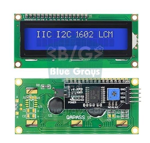
To make the voltmeter independent of the computer, simply print the value on an I2C LCD. Connect the LCD's GND to GND, VCC to 5V, SDA to A4 and SCL to A5. Install the LiquidCrystal I2C library (Frank de Brabander) from the Library Manager. The display's address is usually 0x27, or 0x3F on some modules. The code below shows the live voltage on the top line and the lowest and highest values seen since power-up on the bottom line, so you can also catch the voltage dip on a battery while a motor is running.
1// LCD ekranlı dijital voltmetre (0-25 V, min/maks) / Digital voltmeter with LCD (0-25 V, min/max)
2// LCD: SDA -> A4, SCL -> A5, VCC -> 5V, GND -> GND; sensör S -> A0 / sensor S -> A0
3#include <Wire.h>
4#include <LiquidCrystal_I2C.h>
5
6LiquidCrystal_I2C lcd(0x27, 16, 2);   // adres 0x27 ya da 0x3F / address 0x27 or 0x3F
7
8const int SENSE_PIN = A0;
9const float VREF = 5.00;              // 5V pininde ölçülen / measured on the 5V pin
10const float RATIO = (30000.0 + 7500.0) / 7500.0;   // = 5,0
11const float CAL = 1.000;              // kalibrasyon katsayısı / calibration factor
12
13float vMin = 99.99;
14float vMax = 0.0;
15
16float readVoltage() {
17  analogRead(SENSE_PIN);
18  unsigned long sum = 0;
19  for (int i = 0; i < 32; i++) sum += analogRead(SENSE_PIN);
20  float v = (sum / 32.0) * VREF / 1024.0 * RATIO * CAL;
21  return v < 0.05 ? 0.0 : v;
22}
23
24void printField(float value) {
25  char buf[8];
26  dtostrf(value, 5, 2, buf);          // sabit genişlik: " 9.87" / fixed width: " 9.87"
27  lcd.print(buf);
28}
29
30void setup() {
31  lcd.init();
32  lcd.backlight();
33  lcd.print(F("Voltmetre 0-25V"));
34  delay(1000);
35  lcd.clear();
36}
37
38void loop() {
39  float v = readVoltage();
40  if (v > 0.5) {                      // boştayken min/maks güncelleme / don't update min/max when idle
41    if (v < vMin) vMin = v;
42    if (v > vMax) vMax = v;
43  }
44
45  lcd.setCursor(0, 0);
46  lcd.print(F("V: "));
47  printField(v);
48  lcd.print(F(" V      "));
49
50  lcd.setCursor(0, 1);
51  lcd.print(F("L"));
52  printField(vMin > 99.0 ? 0.0 : vMin);
53  lcd.print(F("  H"));
54  printField(vMax);
55  lcd.print(F("  "));
56  delay(300);
57}
Building the voltmeter with an ESP32
The ESP32 runs on 3.3 V and its pins can't take more than 3.6 V, so use a 100 kΩ + 10 kΩ divider for 0–25 V: 25 V at the input gives 2.27 V at the pin. Connect the divider to one of the ADC1 pins (GPIO 32–39); ADC2 pins don't work while Wi-Fi is on. The ESP32's ADC is 12-bit but not linear at the ends: it barely sees anything below 0.15 V, and its error grows above 2.5 V. The analogReadMilliVolts() function uses calibration data written into the chip at the factory and gives a far more accurate millivolt result than the raw value. To remove the remaining offset, the code applies the two-point calibration from the previous section with the GAIN and OFFSET constants.
1// ESP32 voltmetre: 100k + 10k bölücü ile 0-25 V / ESP32 voltmeter: 0-25 V with a 100k + 10k divider
2// Kaynak + -> 100k -> GPIO 34 -> 10k -> GND, kaynak - -> GND / source + -> 100k -> GPIO 34 -> 10k -> GND
3const int SENSE_PIN = 34;                 // ADC1_CH6, Wi-Fi açıkken de çalışır / works with Wi-Fi on
4const float RATIO = (100000.0 + 10000.0) / 10000.0;   // = 11,0
5const float GAIN = 1.000;                 // iki noktalı kalibrasyon: eğim / two-point calibration: slope
6const float OFFSET = 0.00;                // iki noktalı kalibrasyon: kayma (V) / two-point calibration: offset (V)
7
8float readVoltage() {
9  uint32_t mv = 0;
10  for (int i = 0; i < 64; i++) {
11    mv += analogReadMilliVolts(SENSE_PIN);   // fabrika kalibrasyonlu mV / factory-calibrated mV
12  }
13  float vPin = mv / 64.0 / 1000.0;           // pindeki gerilim (V) / voltage at the pin (V)
14  float v = vPin * RATIO * GAIN + OFFSET;
15  return v < 0.10 ? 0.0 : v;
16}
17
18void setup() {
19  Serial.begin(115200);
20  analogReadResolution(12);                  // 0-4095
21}
22
23void loop() {
24  float v = readVoltage();
25  Serial.printf("Gerilim / Voltage: %.2f V\n", v);
26  delay(500);
27}
Building the voltmeter with a Raspberry Pi Pico (MicroPython)
On the Raspberry Pi Pico the analog inputs are GP26, GP27 and GP28. Connect the same 100 kΩ + 10 kΩ divider as on the ESP32 to GP26. In MicroPython, read_u16() returns the 12-bit result scaled to 0–65535. The Pico's ADC reference is filtered from the 3.3 V rail; for better accuracy, measure between ADC_VREF (pin 35) and GND with a multimeter and enter the value in VREF. There's a bonus in the code too: on the standard Pico, GP29 (ADC3) is wired to an internal divider that divides the board's VSYS supply input by 3. So without any extra parts you can also read the voltage of the battery powering the Pico. On the Pico W and Pico 2 W, GP29 is shared with the wireless chip, so this line doesn't work directly on those boards.
1# Raspberry Pi Pico voltmetre (MicroPython) / Raspberry Pi Pico voltmeter (MicroPython)
2# Kaynak + -> 100k -> GP26 -> 10k -> GND / source + -> 100k -> GP26 -> 10k -> GND
3from machine import ADC
4import time
5
6sense = ADC(26)            # GP26 = ADC0 (pin 31)
7vsys = ADC(29)             # GP29 = VSYS / 3 (yalnız standart Pico / standard Pico only)
8VREF = 3.3                 # ADC_VREF; multimetreyle ölçüp düzelt / measure and correct with a multimeter
9RATIO = (100000 + 10000) / 10000    # = 11.0
10GAIN = 1.000               # iki noktalı kalibrasyon: eğim / two-point calibration: slope
11OFFSET = 0.00              # iki noktalı kalibrasyon: kayma (V) / two-point calibration: offset (V)
12
13
14def pin_voltage(adc, samples=64):
15    total = 0
16    for _ in range(samples):
17        total += adc.read_u16()            # 0-65535
18    return total / samples * VREF / 65535  # pindeki gerilim / voltage at the pin
19
20
21while True:
22    v_in = pin_voltage(sense) * RATIO * GAIN + OFFSET
23    if v_in < 0.05:
24        v_in = 0.0
25    v_sys = pin_voltage(vsys) * 3          # VSYS = GP29 x 3
26    print("Giris / Input: {:.2f} V   VSYS: {:.2f} V".format(v_in, v_sys))
27    time.sleep(0.5)
Adding current to make a wattmeter: ACS712 or INA219
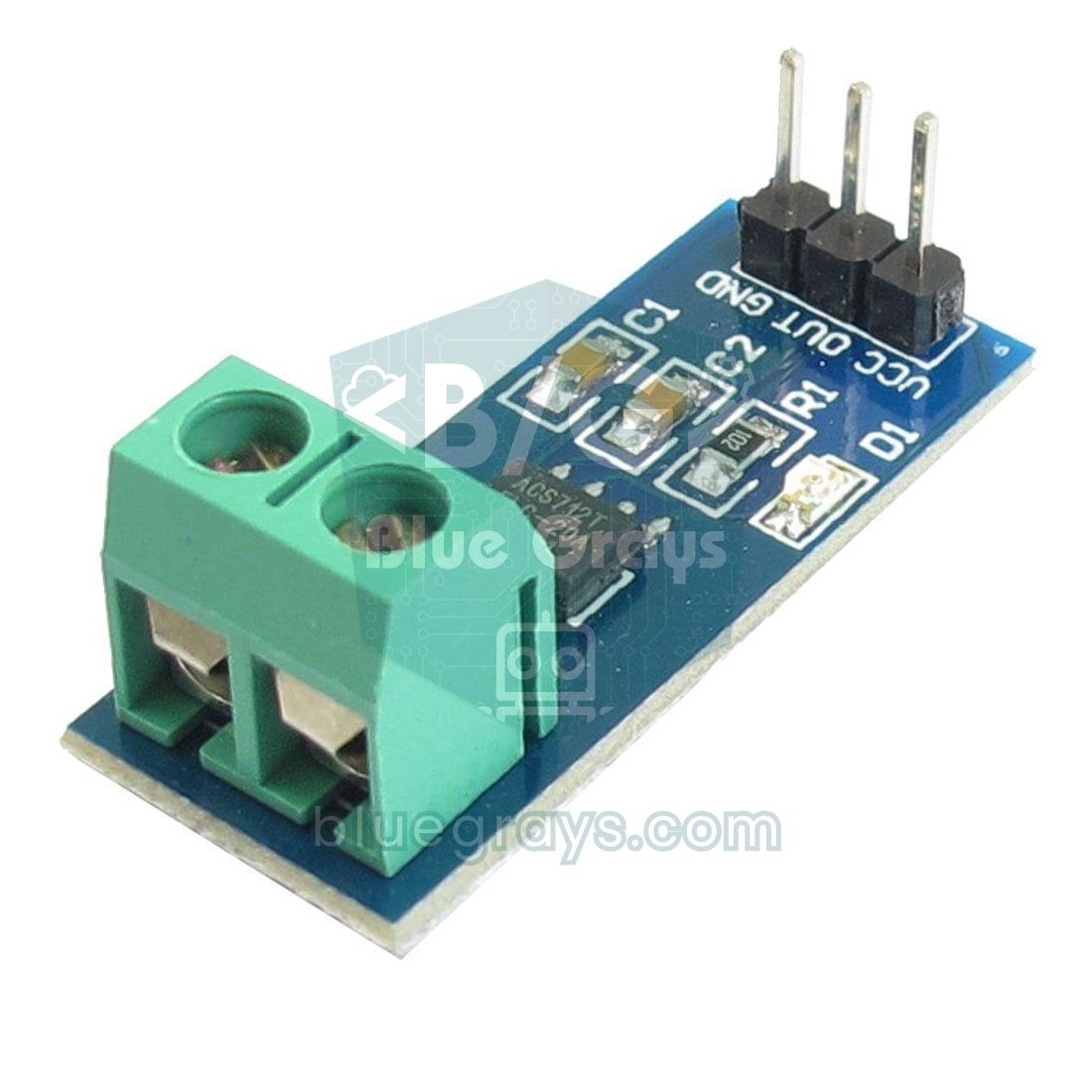
When you add current measurement to a voltmeter, you also get power: P = V × I. If a 12 V battery supplies 1.5 A, the power is 18 W. Add the power up over time and you get energy: an 18 W load running for 2 hours uses 36 Wh. There are two common options. The ACS712 has an analog output, also measures AC current and provides isolation; it simply becomes a second analog channel on your existing voltmeter. The INA219 is a DC power monitor that measures voltage and current in the same chip with 12-bit precision and talks over I2C; on its own it's a ready-made wattmeter.
| Feature | Voltage module + ACS712 (5A) | INA219 module |
|---|---|---|
| Voltage range | 0–25 V (set by the divider) | 0–26 V (inside the chip) |
| Current range | ±5 A | ±3.2 A (with a 0.1 Ω shunt) |
| Current resolution | About 26 mA on an Uno | 0.1 mA |
| AC current | Yes | No |
| Connection | Two analog pins | I2C (SDA, SCL), address 0x40 |
| Best for | Motors, mains-side current and where isolation is needed | Small DC power measurements such as batteries, solar panels and USB devices |
1// INA219 + I2C LCD ile wattmetre: V, A, W ve Wh / Wattmeter with INA219 + I2C LCD: V, A, W and Wh
2// Kaynak + -> INA219 VIN+ ; INA219 VIN- -> yük + ; yük - -> kaynak - -> Arduino GND
3// Source + -> INA219 VIN+ ; INA219 VIN- -> load + ; load - -> source - -> Arduino GND
4#include <Wire.h>
5#include <Adafruit_INA219.h>
6#include <LiquidCrystal_I2C.h>
7
8Adafruit_INA219 ina219;               // varsayılan adres 0x40 / default address 0x40
9LiquidCrystal_I2C lcd(0x27, 16, 2);
10
11float energyWh = 0.0;
12unsigned long lastMs = 0;
13
14void printField(float value, int width, int decimals) {
15  char buf[10];
16  dtostrf(value, width, decimals, buf);
17  lcd.print(buf);
18}
19
20void setup() {
21  Serial.begin(9600);
22  lcd.init();
23  lcd.backlight();
24  if (!ina219.begin()) {              // modül bulunamadı / module not found
25    lcd.print(F("INA219 yok!"));
26    while (true) delay(10);
27  }
28  // ina219.setCalibration_16V_400mA();  // küçük akımlar için daha hassas / finer for small currents
29  lastMs = millis();
30}
31
32void loop() {
33  float busV = ina219.getBusVoltage_V();           // VIN- ile GND arası / between VIN- and GND
34  float shuntMv = ina219.getShuntVoltage_mV();     // şönt üzerindeki düşüm / drop across the shunt
35  float loadV = busV + shuntMv / 1000.0;           // kaynağın gerilimi / source voltage
36  float currentA = ina219.getCurrent_mA() / 1000.0;
37  float powerW = loadV * currentA;
38
39  unsigned long now = millis();
40  energyWh += powerW * (now - lastMs) / 3600000.0; // W x saat = Wh / W x hours = Wh
41  lastMs = now;
42
43  lcd.setCursor(0, 0);
44  printField(loadV, 5, 2);  lcd.print(F("V "));
45  printField(currentA, 6, 3); lcd.print(F("A  "));
46  lcd.setCursor(0, 1);
47  printField(powerW, 6, 2); lcd.print(F("W "));
48  printField(energyWh, 6, 2); lcd.print(F("Wh"));
49
50  Serial.print(loadV, 2);    Serial.print(F(" V, "));
51  Serial.print(currentA, 3); Serial.print(F(" A, "));
52  Serial.print(powerW, 2);   Serial.print(F(" W, "));
53  Serial.print(energyWh, 3); Serial.println(F(" Wh"));
54  delay(500);
55}
The INA219 works out the current from the small voltage drop across the 0.1 Ω shunt resistor between VIN+ and VIN−, so the module goes in series on the positive side of the source (high side). Because the bus voltage is measured between VIN− and GND, the code adds the shunt drop to get the source's real voltage. The default calibration is for 32 V and 2 A; if you'll only measure a few hundred milliamps, enable the setCalibration_16V_400mA() line to narrow the range to 400 mA and improve accuracy at small currents. Energy is found by adding up the current power multiplied by the time elapsed in each loop; it resets when you switch the Arduino off, so to keep it, write the value to EEPROM at intervals. For code that does the same calculation with the ACS712, see the power and energy section of the ACS712 article.
Battery tester: a voltmeter that measures capacity (mAh)
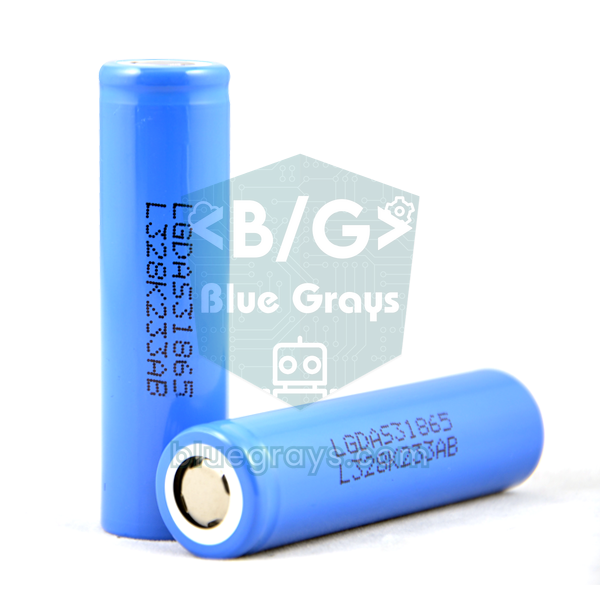
A battery's voltage doesn't tell you exactly how much energy is left in it; a full but worn-out cell can also show 4.1 V. The way to find the real capacity is to discharge the battery through a known load and add up the current over time: mAh = Σ (current × time). In this circuit a MOSFET switches the load on and off, and the Arduino measures the battery voltage and the voltage at the bottom of the load resistor once a second. The difference between the two, divided by the load resistance, gives the current. When the battery reaches its cut-off voltage the MOSFET turns off and the result is printed. At the start, the code also compares the battery's unloaded and loaded voltage to calculate its internal resistance; the higher the internal resistance, the more the battery sags at high current.
| Part | Connection | Note |
|---|---|---|
| Battery + | To A0 through 10 kΩ; also the top of the load resistor | Put 100 nF between A0 and GND |
| 4.7 Ω load resistor | Between battery + and the MOSFET drain | At least 5 W (preferably 10 W) cement resistor; about 0.9 A flows with an 18650 and it gets hot |
| MOSFET drain | Bottom of the load resistor; to A1 through 10 kΩ | Put 100 nF between A1 and GND as well |
| MOSFET source | GND | The battery negative connects here too |
| MOSFET gate | To D9 through 220 Ω; to GND through 100 kΩ | Use a logic-level MOSFET such as the IRLZ44N |
1// Pil kapasite test cihazı: mAh, Wh ve iç direnç / Battery capacity tester: mAh, Wh and internal resistance
2// Pil + -> 10k -> A0 ; pil + -> 4,7 ohm yük -> MOSFET drain ; drain -> 10k -> A1
3// Battery + -> 10k -> A0 ; battery + -> 4.7 ohm load -> MOSFET drain ; drain -> 10k -> A1
4// MOSFET source -> GND ; gate <- D9 (220 ohm), gate -> 100k -> GND ; pil - / battery - -> GND
5const int BAT_PIN = A0;
6const int DRAIN_PIN = A1;
7const int LOAD_PIN = 9;
8const float VREF = 5.00;        // 5V pininde ölçülen / measured on the 5V pin
9const float R_LOAD = 4.7;       // yük direnci, multimetreyle ölç / load resistor, measure it
10const float CUTOFF_V = 3.00;    // Li-ion 3,00 V ; alkalin AA / alkaline AA 0,90 V
11
12float mAh = 0.0;
13float wh = 0.0;
14unsigned long lastMs = 0;
15unsigned long startMs = 0;
16bool running = false;
17
18float readPin(int pin) {
19  analogRead(pin);                          // kanal değişti, ilk okumayı at / discard first reading
20  unsigned long sum = 0;
21  for (int i = 0; i < 32; i++) sum += analogRead(pin);
22  return (sum / 32.0) * VREF / 1024.0;
23}
24
25float loadCurrent(float vBat) {
26  return (vBat - readPin(DRAIN_PIN)) / R_LOAD;   // dirençteki gerilim / R / voltage across R / R
27}
28
29void setup() {
30  Serial.begin(9600);
31  pinMode(LOAD_PIN, OUTPUT);
32  digitalWrite(LOAD_PIN, LOW);              // yük kapalı / load off
33  delay(1000);
34
35  float vOpen = readPin(BAT_PIN);           // yüksüz gerilim / open-circuit voltage
36  if (vOpen < CUTOFF_V + 0.1) {
37    Serial.println(F("Pil zayif ya da takili degil / Battery low or missing"));
38    return;
39  }
40  digitalWrite(LOAD_PIN, HIGH);             // yükü aç / load on
41  delay(1000);
42  float vLoad = readPin(BAT_PIN);
43  float amps = loadCurrent(vLoad);
44  Serial.print(F("Bos / Open: "));
45  Serial.print(vOpen, 3);
46  Serial.print(F(" V  Yuklu / Loaded: "));
47  Serial.print(vLoad, 3);
48  Serial.print(F(" V  Ic direnc / Internal R: "));
49  Serial.print((vOpen - vLoad) / amps * 1000.0, 0);
50  Serial.println(F(" mOhm"));
51
52  running = true;
53  startMs = lastMs = millis();
54}
55
56void loop() {
57  if (!running) return;
58  unsigned long now = millis();
59  if (now - lastMs < 1000) return;          // saniyede bir ölç / measure once per second
60
61  float hours = (now - lastMs) / 3600000.0;
62  lastMs = now;
63  float vBat = readPin(BAT_PIN);
64  float amps = loadCurrent(vBat);
65  mAh += amps * 1000.0 * hours;             // akım x süre / current x time
66  wh += vBat * amps * hours;
67
68  Serial.print((now - startMs) / 1000);
69  Serial.print(F(" s  "));
70  Serial.print(vBat, 3);
71  Serial.print(F(" V  "));
72  Serial.print(amps, 3);
73  Serial.print(F(" A  "));
74  Serial.print(mAh, 0);
75  Serial.println(F(" mAh"));
76
77  if (vBat <= CUTOFF_V) {                   // kesme gerilimi / cut-off voltage
78    digitalWrite(LOAD_PIN, LOW);
79    running = false;
80    Serial.print(F("Bitti / Done: "));
81    Serial.print(mAh, 0);
82    Serial.print(F(" mAh, "));
83    Serial.print(wh, 2);
84    Serial.println(F(" Wh"));
85  }
86}
With a 4.7 Ω load, an 18650 cell discharges at a current that starts around 0.9 A and falls towards 0.65 A; testing a healthy 2500 mAh cell takes about three hours. For Li-ion, never set the cut-off below 3.0 V, or the cell gets damaged. If you're testing an alkaline AA battery, set CUTOFF_V to 0.9 V; it draws about 0.3 A with the same load. You can compare the result with the label and with the battery life calculator. A new 18650's internal resistance measured this way, including the holder and wires, is usually below 0.15 Ω; a cell above 0.3 Ω shouldn't be used for high-current jobs. To understand capacity units, have a look at the mAh and battery capacity article.
Project ideas with an Arduino voltmeter
- Battery monitor and low-voltage alarm: Watch the 12 V battery in a camper or solar setup and sound a buzzer when it drops below 11.8 V.
- Solar panel logger: Write the panel's voltage, and its current via the INA219, to an SD card every minute and work out the daily yield in Wh.
- Bench supply readout: Add a voltmeter and an INA219 to the output of an LM2596 module to turn it into a bench power supply.
- Remote battery monitoring: Send the voltage you measure with an ESP32 to Home Assistant over MQTT, or get a Telegram message when it's low.
- 18650 pack check: Test the capacity of the cells you charge with a TP4056, then match cells of similar capacity to build a balanced pack.
- Big-digit display: Show the value on a 7-segment display or an OLED display instead of the LCD, large enough to read from across the room.
Common mistakes and how to fix them
| Symptom | Likely cause | Fix |
|---|---|---|
| Reading is always 2–5% high or low | VREF is 5.00 V in the code but the board runs on a different voltage | Measure the 5V pin and enter it in VREF, or use the readVcc method |
| Value keeps jumping around | The source negative isn't tied to the Arduino GND, or the line is noisy | Connect a common GND, average readings, add 100 nF at the pin |
| Stuck at the same value at high voltage | The pin reached the reference and the ADC saturated at 1023 | Widen the range by increasing the divider ratio |
| Reading bends near the top and isn't linear | Zener leakage, or the top end of the ESP32 ADC | Keep the pin below 4 V (2.5 V on the ESP32) or use a Schottky |
| On the ESP32 the reading is 0 or frozen once Wi-Fi starts | The divider is on an ADC2 pin | Use one of the ADC1 pins, GPIO 32–39 |
| INA219 shows negative current | VIN+ and VIN− are swapped | Source positive goes to VIN+, load positive to VIN− |
| LCD is lit but shows no text | Wrong I2C address or contrast setting | Find the address with an I2C scanner and turn the trimmer on the back |
An Arduino voltmeter is one of the best ways to learn how measurement works: with two resistors, one formula and a little calibration you get results close to a multimeter's; add a current sensor and it becomes a wattmeter, add a MOSFET and it becomes a battery tester. In the BlueGrays app, the "Digital Voltmeter with LCD" project lets you build the same circuit step by step with a wiring diagram and ready-made code, and from there you can move on to battery monitoring and power measurement projects.
Frequently asked questions
How many volts can an Arduino measure?
You can connect at most 5 V (3.3 V on the ESP32 and Pico) directly to an analog pin. With a voltage divider you can raise that limit as far as you like: 30 kΩ + 7.5 kΩ measures 25 V and 100 kΩ + 10 kΩ measures 50 V. Above a few tens of volts, however, safety and insulation become important, and mains voltage must never be measured this way.
Why is my Arduino voltmeter reading wrong?
The most common reason is the reference voltage: the code says 5.00 V but the board gets 4.7–4.9 V from USB, so every reading shifts by the same ratio. Other causes are 5% resistors, a missing common GND and a divider with too much resistance. Measuring the 5V pin and entering it in the code, or using the readVcc method, and then setting the CAL factor with a known voltage fixes it.
Can I use the 0–25 V voltage sensor module with an ESP32?
You can, but carefully. Because the module's ratio is 5, an ESP32 can only measure up to 16.5 V with it; touch 25 V and 5 V reaches the pin, damaging the ESP32. Building your own 100 kΩ + 10 kΩ divider for the ESP32 is both safer and more accurate, since it keeps the ADC in its linear region.
Can an Arduino measure 230 V AC mains voltage?
Never with a voltage divider: it's potentially lethal and connects the Arduino to the mains. For mains voltage, use a module such as the ZMPT101B, which contains a small transformer and provides galvanic isolation. Its output is AC, so the code calculates the RMS value.
Can an Arduino measure negative voltage?
Not directly; an analog pin can't read below GND and may be damaged. The fix is to shift the signal up towards 5 V with resistors: for example, two equal resistors between the signal and 5 V create a midpoint that maps −5 V to +5 V onto 0–5 V. For more precise work, an op-amp level shifter is used.
Can an Arduino voltmeter be as accurate as a multimeter?
A calibrated Uno voltmeter measures 0–25 V with less than 1% error, which is enough for most hobby work and close to a cheap multimeter. Because of the 10-bit ADC, resolution is limited to about 24 mV on a 25 V range. For better results you can use a 16-bit external ADC such as the ADS1115, 0.1% resistors and a precision reference.
Projects to build after reading this
See all projects
Measuring Light Intensity with an LDR
Want to see how bright your room is as a number? The LDR, a small part that reacts to light, measures the light around it, and the Arduino writes the value to your computer screen every half second. C

Reading Light Intensity with the ESP32 LDR Module
Real-time monitoring of the LDR module's raw ADC value and relative light percentage calculated from dark and light reference values in the Serial Monitor. This percentage is not a lux measurement. Teaches the module’s calibration logic. It is ideal to complete this before Project 10, as it is used to determine the threshold value.
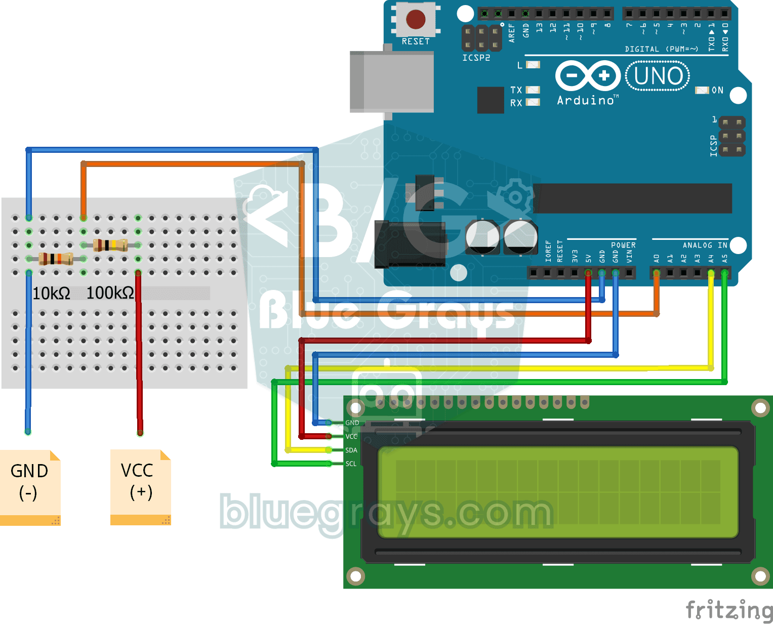
Digital Voltmeter with LCD Display
Find out how much voltage a battery or power adapter gives with a meter you built yourself. A divider made of two resistors brings high voltage down to a level the board can read, and the Arduino calc
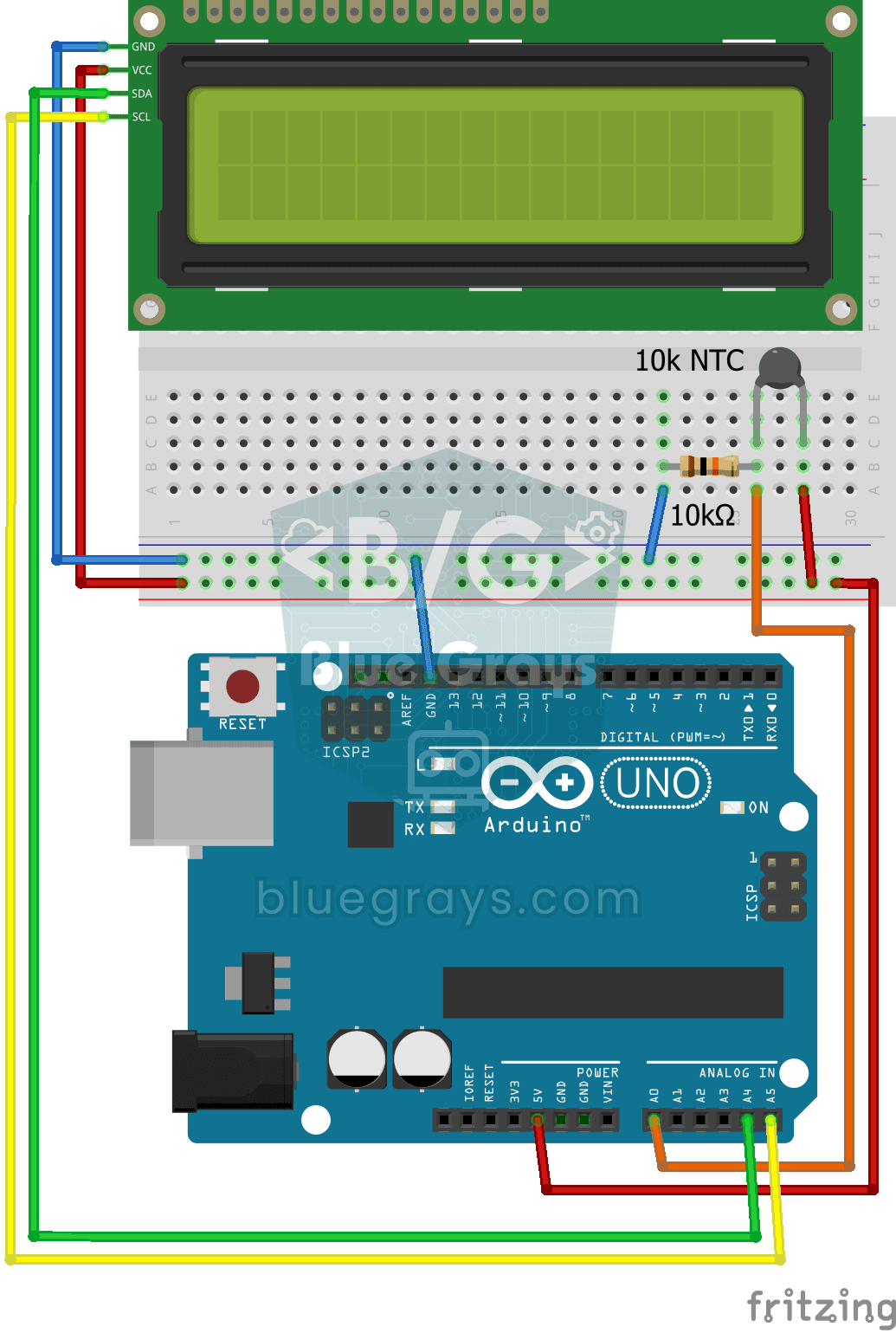
Temperature Measurement with NTC and 2x16 Lcd Display
Measure the temperature around you with a sensor that looks like a tiny bead. This part, called an NTC, lets electricity through more easily as it warms up; the Arduino reads that change, turns it int
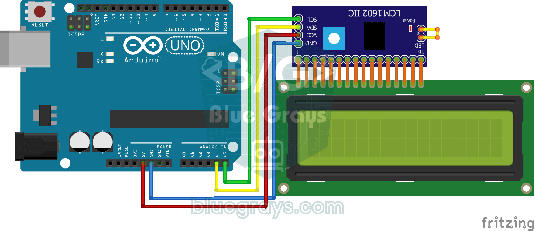
Using LCD Screen with I2C
Give your Arduino its own screen and make it write its first message. The two-line LCD screen hooks up with just a few wires; a greeting appears on the top line, then a second message on the bottom li

ESP32 I2C LCD Display (16x2)
In this project, we display text by connecting a 16x2 character LCD screen to the ESP32 via the I2C protocol. Thanks to I2C, we can control the screen using just two data pins (SDA and SCL), eliminating the waste of 6+ pins associated with a classic parallel connection. The code prints a fixed message on the first line and a counter that increments every second on the second line. Additionally, we run an I2C scanner at the start to print the display’s address to the Serial Monitor (typically 0x2
Measuring Distance Using LCD Display
A tool that measures distance without a ruler: move your hand back and forth in front of the sensor and watch the number change. The HC-SR04 sends out a sound wave and listens for its echo, and the Ar

ESP32 LED Brightness Control with a Potentiometer (Analog → PWM)
In this project, we control the brightness of an LED analogically using a potentiometer. The ESP32's ADC pin reads the 0-3.3V voltage from the potentiometer, and this value is then converted into a PWM (Pulse Width Modulation) signal and sent to the LED. As a result, as you turn the potentiometer, the LED gradually brightens and dims. With Arduino Core 3.0+, analogWrite() can be used directly; on the ESP32-S2/S3, the ADC resolution is fixed at 12-bit.