
LM35 Arduino Temperature Sensor: Wiring, Formula and Code
LM35 Arduino wiring and pinout, the analogRead to °C formula, 0.1 °C resolution with the 1.1 V reference, averaging, ESP32 and Pico code, LM35 vs DS18B20.
The LM35 is a cheap three-legged analog temperature sensor that turns temperature directly into a voltage in degrees Celsius. Using the LM35 with Arduino needs no library and no complicated protocol: you connect the middle leg to an analog pin, read it with analogRead() and get the temperature with a one-line formula. Its output rises by exactly 10 mV for every 1 °C, so it gives 250 mV at 25 °C and 1 V at 100 °C.
In this guide you'll learn how the LM35 works, its pinout and the reverse-wiring mistake almost everyone makes once, how to calculate °C from the analogRead value, how to make your readings more than four times finer with the Arduino Uno's 1.1 V internal reference, and how to calm jittery values by averaging. Then you'll see what to watch out for on the 3.3 V ESP32 and Raspberry Pi Pico, how negative temperatures are measured, and when to choose the LM35 over the DS18B20 or DHT11.
What is the LM35 and how does it work?
Inside the LM35 there are two transistors running at different current densities. The difference between their base-emitter voltages changes in direct proportion to absolute temperature; this technique is called delta-VBE. An internal amplifier boosts this tiny difference and scales it so the output is 0 V at 0 °C. That's why, unlike Kelvin-based sensors such as the LM335, you don't need to subtract a large constant voltage from the output: temperature (°C) = output voltage (mV) / 10. The sensor is trimmed at wafer level during production, so it needs no extra calibration and its output curve is almost perfectly straight; its typical non-linearity is only ±0.25 °C.
| Feature | Value |
|---|---|
| Output | 10 mV/°C, 0 V at 0 °C (250 mV at 25 °C, 1000 mV at 100 °C) |
| Supply voltage | 4–30 V |
| Supply current | Less than 60 µA (typically 56 µA at 5 V) |
| Self-heating | About 0.08 °C in still air |
| Non-linearity | Typically ±0.25 °C |
| Output impedance | 0.1 Ω with a 1 mA load |
| Capacitive load | Up to 50 pF without extra precautions |
| Package | TO-92 (most common), TO-220, SOIC-8 and metal TO-46 |
The LM35 isn't a single part but a family. The letter suffix sets the measuring range and the guaranteed accuracy, while a trailing Z marks the plastic TO-92 package. According to the datasheet, the plastic TO-92 versions are the LM35C, LM35CA and LM35D, and most parts sold as "LM35" in hobby shops are actually the LM35DZ. So your sensor is most likely guaranteed only for 0–100 °C and may be off by up to ±1.5 °C at 25 °C, although its typical error is around ±0.6 °C. Read the marking on the part to find out which one you have.
| Model | Measuring range | Guaranteed accuracy at 25 °C | Worst case at range limits |
|---|---|---|---|
| LM35A | −55 … +150 °C | ±0.5 °C | ±1 °C |
| LM35 | −55 … +150 °C | ±1 °C | ±1.5 °C |
| LM35CA | −40 … +110 °C | ±0.5 °C | ±1.5 °C |
| LM35C | −40 … +110 °C | ±1 °C | ±2 °C |
| LM35D (LM35DZ) | 0 … +100 °C | ±1.5 °C | ±2 °C |
LM35 pinout and the most common reverse-wiring mistake
With the flat face of the LM35 towards you and the legs pointing down, the order from left to right is: pin 1 +Vs (supply), pin 2 Vout (output) and pin 3 GND (ground). Because the drawing in the datasheet is a bottom view, many people flip it in their heads and wire it the wrong way round. On LM35 modules sold on a small board, the pins are usually labelled VCC (or +), OUT (or S) and GND (or −); in that case, trust the labels on the board.
LM35 Arduino wiring: Uno, ESP32 and Pico
| LM35 pin | Arduino Uno | ESP32 | Raspberry Pi Pico |
|---|---|---|---|
| 1 · +Vs (left) | 5V | 5V / VIN (5 V from USB) | VBUS, pin 40 (5 V from USB) |
| 2 · Vout (middle) | A0 | GPIO 34 (ADC1) | GP26 / ADC0, pin 31 |
| 3 · GND (right) | GND | GND | AGND pin 33 or GND pin 38 |
| 0.1 µF capacitor | Between +Vs and GND, close to the sensor | Between +Vs and GND, close to the sensor | Between +Vs and GND, close to the sensor |
From analogRead to °C: the LM35 formula
The Arduino Uno's analog-to-digital converter (ADC) has 10 bits: it splits the range between 0 V and the reference voltage into 1024 steps and gives you a number from 0 to 1023. Since the reference is 5 V by default, each step is 5 / 1024 = 4.88 mV. First you convert the raw value to a voltage, then the voltage to a temperature: voltage = raw × 5.0 / 1024 and temperature = voltage × 100. Combined, temperature ≈ raw × 0.488. Some examples use 1023 instead of 1024; the difference is one part in a thousand and negligible next to the LM35's own error, but 1024 is the correct value. If you want to understand the ADC in more detail, see the article on analog-to-digital conversion (ADC).
| analogRead value | Voltage (5 V reference) | Temperature |
|---|---|---|
| 41 | 0.200 V | 20.0 °C |
| 51 | 0.249 V | 24.9 °C |
| 52 | 0.254 V | 25.4 °C |
| 61 | 0.298 V | 29.8 °C |
| 205 | 1.001 V | 100.1 °C |
Look closely at the table: at room temperature the ADC only produces a number around 50, and a change of a single step moves the temperature by about 0.5 °C. That's why your reading jumps back and forth between 24.9 and 25.4; the sensor isn't faulty, that's simply the resolution of the 5 V reference. We'll fix this shortly with the internal reference.
Your first measurement, step by step
- Plug the LM35 into the breadboard; with the flat face towards you, connect the left leg to 5V and the right leg to GND.
- Connect the middle leg (Vout) to A0 with a jumper wire. If you have one, add a 0.1 µF capacitor between +Vs and GND.
- Connect the Arduino over USB and touch the sensor after a few seconds: if it feels like room temperature, all is well; if it's hot, the wiring is reversed.
- Upload the code below and open the Serial Monitor at 9600 baud.
- Hold the sensor between your fingers; you should see the value rise slowly and fall back when you let go.
1const int LM35_PIN = A0;   // LM35 orta bacak (Vout) / LM35 middle leg (Vout)
2
3void setup() {
4  Serial.begin(9600);
5}
6
7void loop() {
8  int raw = analogRead(LM35_PIN);          // 0–1023 ham değer / raw value 0–1023
9  float voltage = raw * 5.0 / 1024.0;      // 5 V referansla volta çevir / convert to volts (5 V reference)
10  float tempC = voltage * 100.0;           // 10 mV/°C: 0,25 V = 25 °C / 0.25 V = 25 °C
11
12  Serial.print(F("Ham / Raw: "));
13  Serial.print(raw);
14  Serial.print(F("  Gerilim / Voltage: "));
15  Serial.print(voltage, 3);
16  Serial.print(F(" V  Sicaklik / Temp: "));
17  Serial.print(tempC, 1);
18  Serial.println(F(" C"));
19  delay(1000);
20}
Every second the code reads the raw value on A0, converts it first to a voltage and then to a temperature, and prints all three to the Serial Monitor. Printing the raw value is very handy when debugging: if it's always 0, no voltage is coming from Vout; if it's close to 1023, the analog pin has accidentally been connected to 5 V; if it jumps around randomly, A0 is floating. Writing fixed strings inside the F() macro saves the Uno's 2 KB of RAM. You'll find more Serial Monitor tips in the article on using the Arduino Serial Monitor.
Boosting resolution with the 1.1 V internal reference
The 5 V reference has two problems. The first is the coarse resolution you just saw. The second is sneakier: the 5 V coming from USB is often anywhere between 4.7 and 5.1 V, and because your code says 5.0, the difference goes straight into the temperature. For example, if your board actually runs at 4.8 V, you'll see 25 °C as 26 °C, and as your computer's USB port sags under load, the temperature seems to change on its own. The fix is to use the 1.1 V internal reference built into the ATmega328P on the Arduino Uno and Nano. After analogReference(INTERNAL), each step is 1.1 / 1024 = 1.07 mV, or about 0.11 °C. In return you can measure at most 1.1 V, i.e. 110 °C, which is plenty for the LM35DZ's 0–100 °C range anyway.
| Reference | Command | One step | Temperature step | Highest measurable value |
|---|---|---|---|---|
| 5 V (default) | analogReference(DEFAULT) | 4.88 mV | 0.49 °C | 150 °C (sensor limit) |
| 3.3 V (wired to AREF) | analogReference(EXTERNAL) | 3.22 mV | 0.32 °C | 150 °C (sensor limit) |
| 1.1 V internal | analogReference(INTERNAL) | 1.07 mV | 0.11 °C | 110 °C |
The 1.1 V reference isn't exactly 1.1 V on every chip; according to the ATmega328P datasheet it can be anywhere from 1.0 to 1.2 V. Without calibration, that means a scale error of up to 9%. The fix is easy: upload the code below, measure the voltage between the AREF pin and GND with a multimeter, and write the value into the VREF constant (e.g. const float VREF = 1.083;). You only need to do this once per board, and the result stays valid. The code also averages 32 samples for every reading:
1const int LM35_PIN = A0;
2const float VREF = 1.1;     // AREF'te ölçtüğün değeri yaz (ör. 1.083) / write the voltage you measured on AREF (e.g. 1.083)
3const int SAMPLES = 32;     // ortalama için ölçüm sayısı / number of samples to average
4
5void setup() {
6  Serial.begin(9600);
7  analogReference(INTERNAL);        // Uno/Nano: 1,1 V dahili referans / 1.1 V internal reference
8  for (int i = 0; i < 5; i++) {     // referans değişti, ilk okumaları at / discard the first readings after switching
9    analogRead(LM35_PIN);
10    delay(10);
11  }
12}
13
14float readTempC() {
15  long sum = 0;
16  for (int i = 0; i < SAMPLES; i++) {
17    sum += analogRead(LM35_PIN);
18    delay(2);
19  }
20  float raw = sum / (float)SAMPLES;       // ortalama ham değer / average raw value
21  return raw * VREF / 1024.0 * 100.0;     // her basamak ~0,107 °C / each step is ~0.107 °C
22}
23
24void loop() {
25  float t = readTempC();
26  Serial.print(F("Sicaklik / Temp: "));
27  Serial.print(t, 2);
28  Serial.println(F(" C"));
29  if (t > 108.0) {
30    Serial.println(F("Uyari: 1,1 V sinirina yakin / Warning: close to the 1.1 V limit"));
31  }
32  delay(1000);
33}Averaging and reducing noise
A single analogRead can wobble by a step or two because of noise on the wires and ripple on the supply. The simplest and most effective fix is to average several readings: random noise drops with the square root of the number of samples, so averaging 16 readings cuts the noise to a quarter and 64 readings to an eighth. Temperature changes slowly, so dozens of readings taken within a few milliseconds cost you nothing. For an even smoother curve, use an exponential filter: filtered = filtered + 0.1 × (new − filtered). This filter takes only 10 percent of each new reading into account and keeps a single variable in memory. We compare other methods, such as the moving average and the median, in the article on filtering sensor data.
- Discard the first reading after switching channels: if you read several analog sensors, the ADC's sampling capacitor briefly holds the voltage of the previous channel; read the same pin twice and ignore the first result.
- Run the sensor's GND straight to the Arduino's GND pin: if the current of a relay, motor or LED strip flows through the same ground wire, millivolt shifts appear, and on the LM35 every 10 mV equals one degree.
- Keep the cable short and away from power wires: long, unshielded wires act like antennas; use twisted or shielded cable if needed.
- Keep the sensor away from heat sources: an LM35 right next to a voltage regulator, an ESP32 module or a relay measures the board's temperature, not the room's.
- Calibrate the offset once: leave the LM35 next to a reliable thermometer and subtract the constant difference in your code.
LM35 with ESP32: 3.3 V supply and ADC linearity
The ESP32 runs on 3.3 V, but the LM35's datasheet requires at least 4 V of supply. An LM35 powered from 3.3 V may seem to work at room temperature, but its accuracy isn't guaranteed. The right way is to power the sensor from the board's 5V pin (VIN on some boards), i.e. the 5 V coming from USB. This won't harm the ESP32, because even at its hottest (150 °C) the LM35's output never exceeds 1.5 V. Always connect the output to an ADC1 pin (GPIO 32–39), because the ADC2 pins can't be used while Wi-Fi is on. For your board's detailed pin map, see the Pinout tool, and if you're new to the ESP32, read What is the ESP32.
The second issue is the linearity of the ESP32's ADC. It has 12 bits (0–4095) but isn't linear at the ends: it can barely tell voltages below 100 mV apart, and its deviation differs from board to board. Since the LM35 outputs only 200–300 mV at room temperature, this affects you directly. The fix has two steps: choose the attenuation to match the LM35's voltage range, and instead of the raw value use analogReadMilliVolts(), which applies the calibration data written into the chip during production. Because this function returns millivolts directly, you just divide the result by 10 to get the temperature.
| Attenuation | Accurately measured range | LM35 equivalent |
|---|---|---|
| ADC_0db | 100–950 mV | 10–95 °C |
| ADC_2_5db | 100–1250 mV | 10–125 °C |
| ADC_6db | 150–1750 mV | 15–150 °C |
| ADC_11db (default) | 150–2450 mV | 15–150 °C, coarsest resolution |
1const int LM35_PIN = 34;     // ADC1_CH6, Wi-Fi açıkken de çalışır / works while Wi-Fi is on
2const int SAMPLES = 64;      // ortalama için ölçüm sayısı / number of samples to average
3
4void setup() {
5  Serial.begin(115200);
6  analogReadResolution(12);                       // 0–4095
7  analogSetPinAttenuation(LM35_PIN, ADC_2_5db);   // ~100–1250 mV, yani 10–125 °C / i.e. 10–125 °C
8}
9
10void loop() {
11  uint32_t sum = 0;
12  for (int i = 0; i < SAMPLES; i++) {
13    sum += analogReadMilliVolts(LM35_PIN);        // kalibre edilmiş mV / calibrated millivolts
14    delay(1);
15  }
16  float mv = sum / (float)SAMPLES;
17  float tempC = mv / 10.0;                        // 10 mV = 1 °C
18  Serial.printf("Gerilim / Voltage: %.1f mV  Sicaklik / Temp: %.2f C\n", mv, tempC);
19  delay(1000);
20}LM35 with Raspberry Pi Pico and MicroPython
The Pico's 12-bit ADC is on pins GP26, GP27 and GP28; as its reference it uses ADC_VREF, a filtered version of the 3.3 V rail. In MicroPython, read_u16() scales the result to 0–65535, so voltage = raw × 3.3 / 65535. The theoretical resolution is 0.8 mV, or about 0.08 °C, but in practice the Pico's ADC is a bit noisy and shows small jumps at certain values, so averaging is a must here too. Power the LM35 from VBUS (pin 40), which carries the 5 V from USB; if you run the Pico from batteries instead of USB, make sure the voltage on VSYS is above 4 V and power the sensor from there. If you're using a Pico for the first time, you'll find MicroPython setup in What is the Raspberry Pi Pico.
1from machine import ADC, Pin
2import time
3
4# Pin(23, Pin.OUT, value=1)  # yalnız Pico (W değil): regülatör PWM modu, daha az gürültü / Pico (not W) only: SMPS PWM mode, less noise
5lm35 = ADC(26)               # GP26 = ADC0, fiziksel pin 31 / physical pin 31
6VREF = 3.3                   # ADC_VREF'i multimetreyle ölçüp yaz / measure ADC_VREF with a multimeter
7SAMPLES = 64                 # ortalama için ölçüm sayısı / number of samples to average
8
9
10def read_temp_c():
11    total = 0
12    for _ in range(SAMPLES):
13        total += lm35.read_u16()   # 0–65535, 12 bit sonuç 16 bite ölçeklenir / 12-bit result scaled to 16 bits
14    raw = total / SAMPLES
15    volts = raw * VREF / 65535
16    return volts * 100             # 10 mV/°C
17
18
19while True:
20    t = read_temp_c()
21    print("Sicaklik / Temp: {:.2f} C".format(t))
22    time.sleep(1)
The Pico's chip also has a temperature sensor (ADC(4)), but it measures the chip's own temperature, not the room, and usually reads a few degrees high while running; for room temperature you need an external sensor like the LM35. For cleaner results on a standard Pico, you can set GP23 HIGH to put the board's power regulator into PWM mode; this reduces ripple on ADC_VREF but uses a little more current at idle. On the Pico W this pin is reserved for the wireless chip, which is why that line is left commented out in the code.
Measuring negative temperatures with the LM35
In the basic circuit the LM35 only measures from 2 °C to 150 °C, because its output stage can source current but can sink almost none, so the output can't go below ground. For negative temperatures the datasheet shows two options. The first is to connect the output to a negative supply through a resistor (R = Vs / 50 µA; 100 kΩ for −5 V), which is rarely used in Arduino projects because there's no negative supply. The second is the single-supply method: you lift the LM35's GND pin about 1 V above ground with two diodes in series (e.g. 1N4148), connect an 18 kΩ resistor between the output and ground, then read the output on A0 and the LM35's GND pin on A1. The temperature is (A0 voltage − A1 voltage) × 100. To keep at least 4 V across the LM35's own pins in this circuit, power +Vs from VIN (e.g. a 9 V adapter) instead of 5 V and use the 5 V reference. Remember that the common LM35DZ isn't guaranteed below 0 °C; if you often need negative readings, the DS18B20 is far less hassle.
LM35 vs DS18B20 vs DHT11
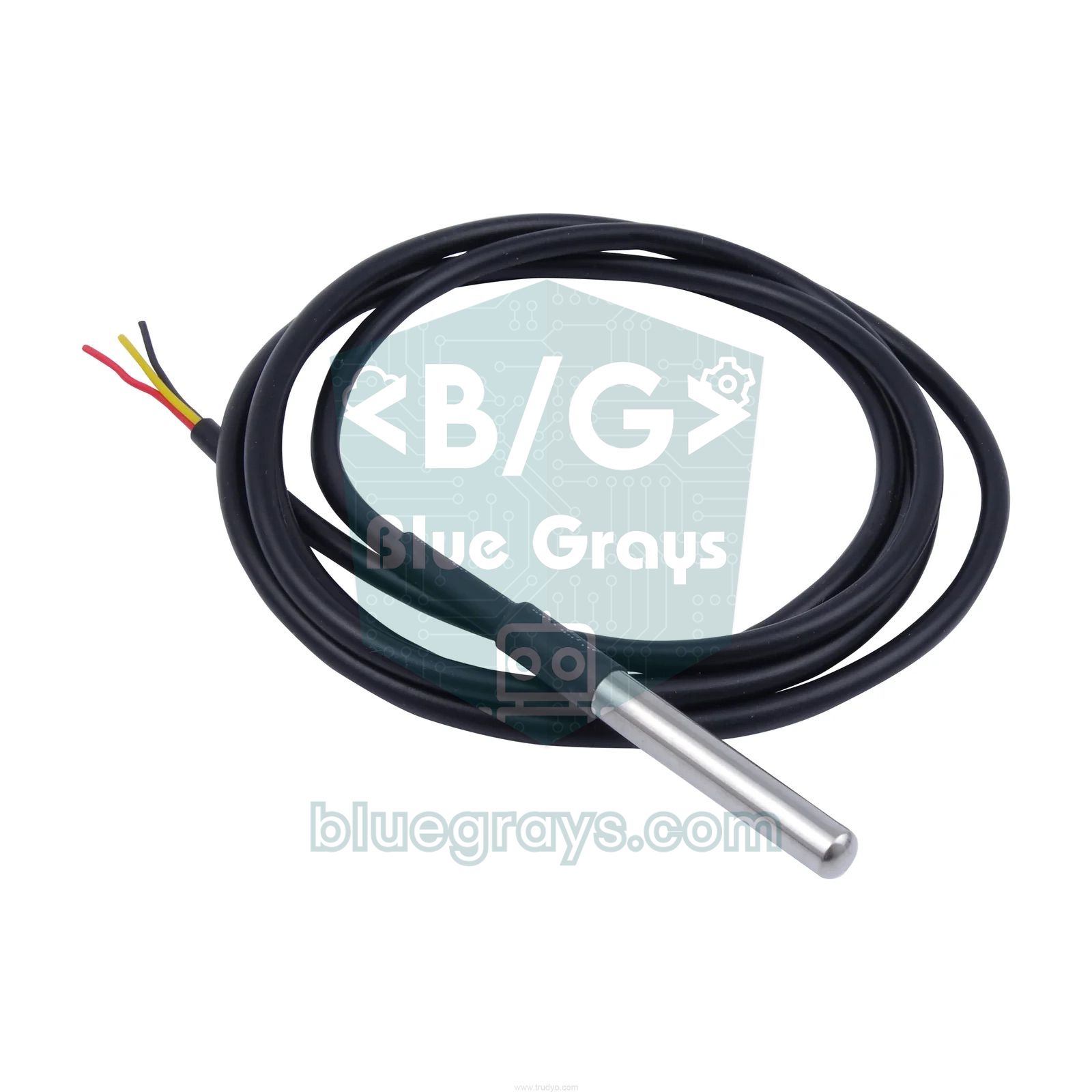
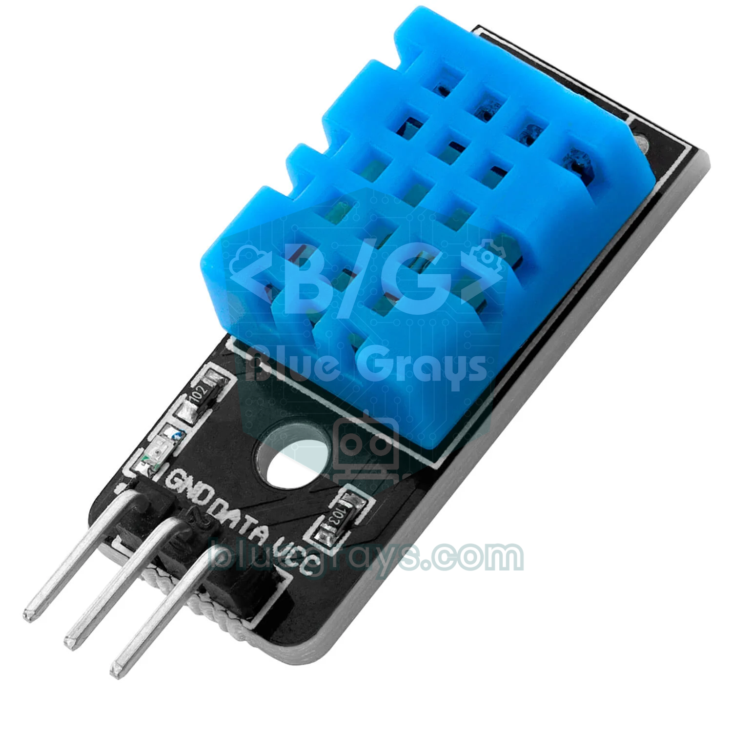
| Feature | LM35 (LM35DZ) | DS18B20 | DHT11 |
|---|---|---|---|
| Output | Analog, 10 mV/°C | Digital (1-Wire) | Digital (single wire) |
| Measuring range | 0 … +100 °C (LM35: −55 … +150 °C) | −55 … +125 °C | 0 … +50 °C |
| Accuracy | Typically ±0.6 °C, at most ±1.5 °C at 25 °C | ±0.5 °C (−10 … +85 °C) | ±2 °C |
| Supply | 4–30 V | 3.0–5.5 V | 3–5.5 V |
| Humidity | No | No | Yes |
| Library | Not needed | OneWire + DallasTemperature | DHT sensor library |
| Reading time | Instant, continuous output | Up to 750 ms at 12 bits | At most 1 reading per second |
| With ESP32 and Pico | With a 5 V supply; mind the ADC limits | Directly at 3.3 V | Directly at 3.3 V |
| Several sensors on one pin | No, one analog pin each | Yes | No |
| Waterproof version | No, you must seal it yourself | Stainless steel probe | No |
In short: if you want a simple thermometer that reacts quickly, needs no library, uses a single analog pin and runs on a 5 V Arduino, the LM35 is ideal; it's also the most instructive sensor for learning analog readings and ADC references. If the cable is long, if you need negative temperatures, if the sensor goes into a liquid, or if you're working with 3.3 V boards such as the ESP32 and Pico, the DS18B20 is the better choice. If you also want humidity, use the DHT11 or its more accurate sibling, the DHT22. For a broader comparison that also covers NTC thermistors, the BME280 and others, see Arduino temperature sensors compared.
LM35 project ideas
The most popular LM35 project is a thermostat that switches on a fan when the temperature exceeds a set value. The key is hysteresis: if the fan turns on at 30 °C and off at 28 °C, the relay won't click on and off every second when the temperature hovers right at the threshold, and its contacts won't wear out. You can drive the fan with a relay module connected to D7:
1const int LM35_PIN = A0;
2const int RELAY_PIN = 7;          // röle modülünün IN pini / relay module IN pin
3const float ON_TEMP = 30.0;       // bu değerde fan açılır / fan turns on here
4const float OFF_TEMP = 28.0;      // bu değerde fan kapanır / fan turns off here
5const float VREF = 1.1;           // ölçtüğün AREF değeri / your measured AREF value
6bool fanOn = false;
7
8float readTempC() {
9  long sum = 0;
10  for (int i = 0; i < 32; i++) {
11    sum += analogRead(LM35_PIN);
12  }
13  return (sum / 32.0) * VREF / 1024.0 * 100.0;
14}
15
16void setup() {
17  Serial.begin(9600);
18  pinMode(RELAY_PIN, OUTPUT);
19  digitalWrite(RELAY_PIN, LOW);
20  analogReference(INTERNAL);      // 1,1 V referans / 1.1 V reference
21  analogRead(LM35_PIN);           // ilk okumayı at / discard the first reading
22  delay(10);
23}
24
25void loop() {
26  float t = readTempC();
27  if (!fanOn && t >= ON_TEMP) fanOn = true;      // eşik aşıldı / threshold exceeded
28  if (fanOn && t <= OFF_TEMP) fanOn = false;     // yeterince soğudu / cooled down enough
29  digitalWrite(RELAY_PIN, fanOn ? HIGH : LOW);   // aktif-HIGH röle varsayıldı / assumes an active-HIGH relay
30  Serial.print(t, 1);
31  Serial.println(fanOn ? " C  fan ON" : " C  fan OFF");
32  delay(1000);
33}- Adjustable fan thermostat: combine the code above with a DC fan and a relay, and raise or lower the threshold with two buttons.
- Digital thermometer with LCD: show the temperature on an I2C LCD or an OLED display along with the day's minimum and maximum.
- Overheating alarm: sound a buzzer and light an LED when a power supply, a battery charger or a 3D printer motor gets too hot.
- Wi-Fi room thermometer: show the temperature measured by the ESP32 on a web page you open on your phone.
- Greenhouse and incubator control: build a system that manages a heater and a fan based on temperature; details in the smart greenhouse project article.
- Temperature logger: write a reading to an SD card every minute and plot the daily temperature curve in Excel.
Common mistakes and how to fix them
| Symptom | Likely cause | Fix |
|---|---|---|
| The sensor gets too hot to touch | +Vs and GND are swapped | Cut the power at once; with the flat face towards you the order must be +Vs, Vout, GND |
| The value is always 0 | No supply reaches the sensor, or Vout is wired to a different pin than in the code | Measure 5 V between +Vs and GND with a multimeter and check that Vout goes to A0 |
| Values jump around randomly | A0 is floating or the breadboard contact is poor | Replace the jumper wire and move the sensor to another row on the breadboard |
| The value toggles in 0.5 °C steps | Resolution of the 5 V reference | Use analogReference(INTERNAL) and average |
| The value jumps when a relay or motor switches | Voltage drop and noise on the shared ground | Run the sensor's GND straight to the Arduino and add a 0.1 µF capacitor |
| Reads 2–3 °C above the real temperature | The sensor sits next to the regulator or the ESP32 module | Move the sensor away from the board on a cable |
| Other analog sensors read 1023 | The INTERNAL reference limits every analog input to 1.1 V | Read the other sensors with the 5 V reference or divide their voltage |
| Nonsense values on the ESP32 in the cold | The ESP32 ADC can't measure below 100 mV accurately | Use a DS18B20 below 10 °C |
The LM35 is a perfect starter part for learning analog sensor readings, ADC references and signal filtering: you start with a single formula, then use the right reference, averaging and calibration to make your measurement as trustworthy as a thermometer. You'll use the same approach with other analog sensors such as the NTC thermistor. In the BlueGrays app you'll find projects like temperature measurement with an NTC and LCD, temperature and humidity with the DHT11, an ESP32 temperature station with LCD and a temperature logger, each with step-by-step circuit diagrams and ready-to-use code.
Frequently asked questions
What voltage does the LM35 need, and can it run on 3.3 V?
The LM35's datasheet specifies a supply of 4–30 V. On 3.3 V it usually still gives a reading at room temperature, but its accuracy isn't guaranteed. On the ESP32 and Pico, power the sensor from the 5 V pin (VIN or VBUS); its output never exceeds 1.5 V, so it can go straight to a 3.3 V analog input.
Why is my LM35 getting hot?
In normal operation the LM35 draws only about 60 µA and heats itself by less than 0.1 °C; if it feels hot, the supply and GND pins are almost always reversed. With the flat face towards you, the correct order from left to right is +Vs, Vout, GND. Cut the power immediately; a sensor left reversed for long can be permanently damaged.
What is the LM35 temperature formula?
On an Arduino Uno with the 5 V reference, temperature (°C) = analogRead × 5.0 / 1024 × 100, or roughly analogRead × 0.488. With the 1.1 V internal reference the factor becomes 1.1 / 1024 × 100 ≈ 0.107. On the ESP32, just divide the result of analogReadMilliVolts() by 10.
Can the LM35 measure negative temperatures?
In the basic circuit the LM35 only measures from 2 °C to 150 °C. For negative values you need to pull the output to a negative supply through a resistor, or lift the GND pin with two diodes and measure the difference with two analog inputs; the sensor must also be a version rated below zero, such as the LM35 or LM35C. In practice, the DS18B20 is much easier for sub-zero temperatures.
Which is better, the LM35 or the DS18B20?
In a 5 V Arduino project with a short cable, the LM35 is very practical because it needs no library and reads instantly. For long cables, negative temperatures, measurements in liquids, several sensors on one pin or 3.3 V boards, the digital DS18B20 gives more accurate and reliable results. At room temperature the LM35A and DS18B20 are similarly accurate, while the common LM35DZ lags a little behind.
Why does my LM35 reading keep changing?
With the 5 V reference each ADC step equals about 0.5 °C, so the value toggles between two steps, and ripple on the USB voltage affects the result too. Switch to the 1.1 V reference with analogReference(INTERNAL), average 16–64 readings and add a 0.1 µF capacitor across the sensor's supply pins. If there's a relay or motor, run the sensor's GND straight to the Arduino.
Projects to build after reading this
See all projects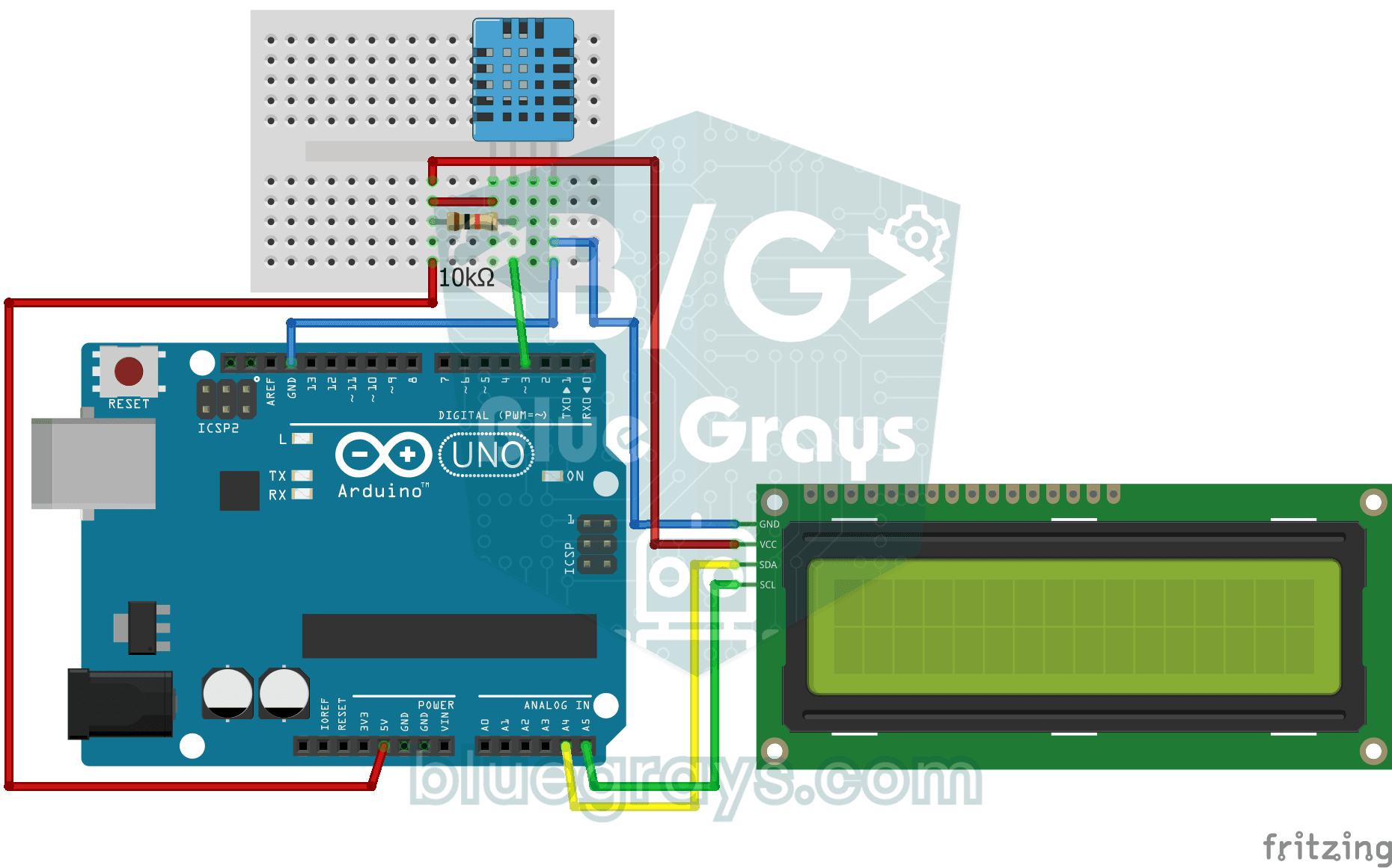
Temperature and Humidity with DHT11
How warm is your room, and is the air humid or dry? The DHT11 sensor measures temperature and humidity, and the Arduino writes the values on a two-line LCD screen, refreshing every couple of seconds.

Measuring Light Intensity with an LDR
Want to see how bright your room is as a number? The LDR, a small part that reacts to light, measures the light around it, and the Arduino writes the value to your computer screen every half second. C

Reading Light Intensity with the ESP32 LDR Module
Real-time monitoring of the LDR module's raw ADC value and relative light percentage calculated from dark and light reference values in the Serial Monitor. This percentage is not a lux measurement. Teaches the module’s calibration logic. It is ideal to complete this before Project 10, as it is used to determine the threshold value.
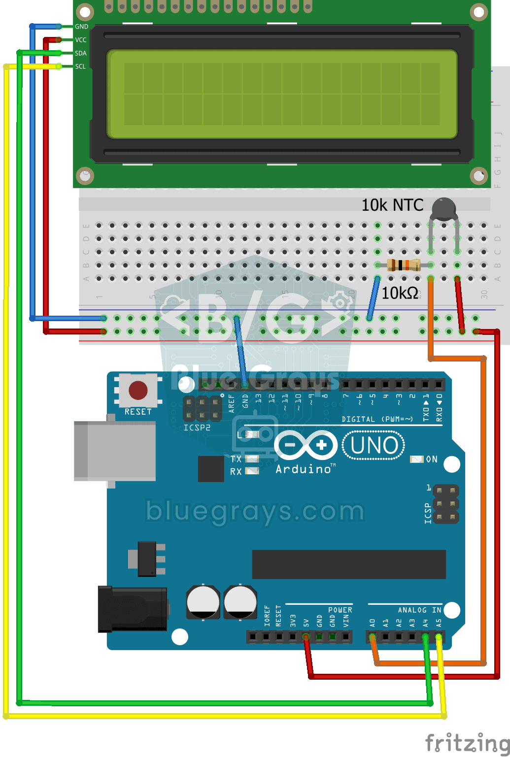
Temperature Measurement with NTC and 2x16 Lcd Display
Measure the temperature around you with a sensor that looks like a tiny bead. This part, called an NTC, lets electricity through more easily as it warms up; the Arduino reads that change, turns it int
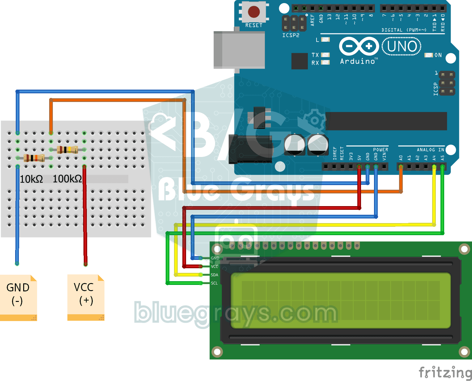
Digital Voltmeter with LCD Display
Find out how much voltage a battery or power adapter gives with a meter you built yourself. A divider made of two resistors brings high voltage down to a level the board can read, and the Arduino calc

ESP32 DHT22 Temperature and Humidity (with LCD Display)
This project measures ambient temperature and humidity using a DHT22 sensor and displays the data in real time on a 16x2 I2C LCD. Data is read from the sensor using the one-wire protocol via the Adafruit DHT library. This project serves as the foundation for IoT weather stations, smart home automation, or environmental monitoring systems in greenhouses. Communication with the DHT22 is established via the ESP32's GPIO 4 pin.
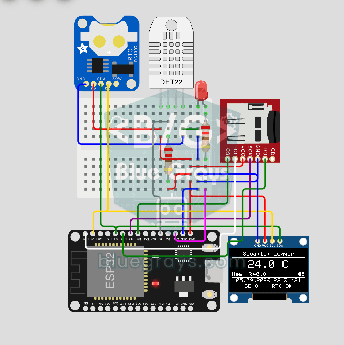
ESP32 Temperature Data Logger (DHT22 + DS1307 RTC + microSD + OLED)
Build a timestamped temperature logger with ESP32! Read DHT22 temperature/humidity every minute, get real-world time from DS1307 RTC, and log to microSD card as CSV. The OLED displays live temperature (large font), humidity percentage, timestamp, and log counter. The /temp_log.csv file on the SD card opens in Excel, Google Sheets, or Python pandas for analysis — perfect for greenhouse monitoring, home/room temperature tracking, laboratory data collection, food storage conditions, or beehiv
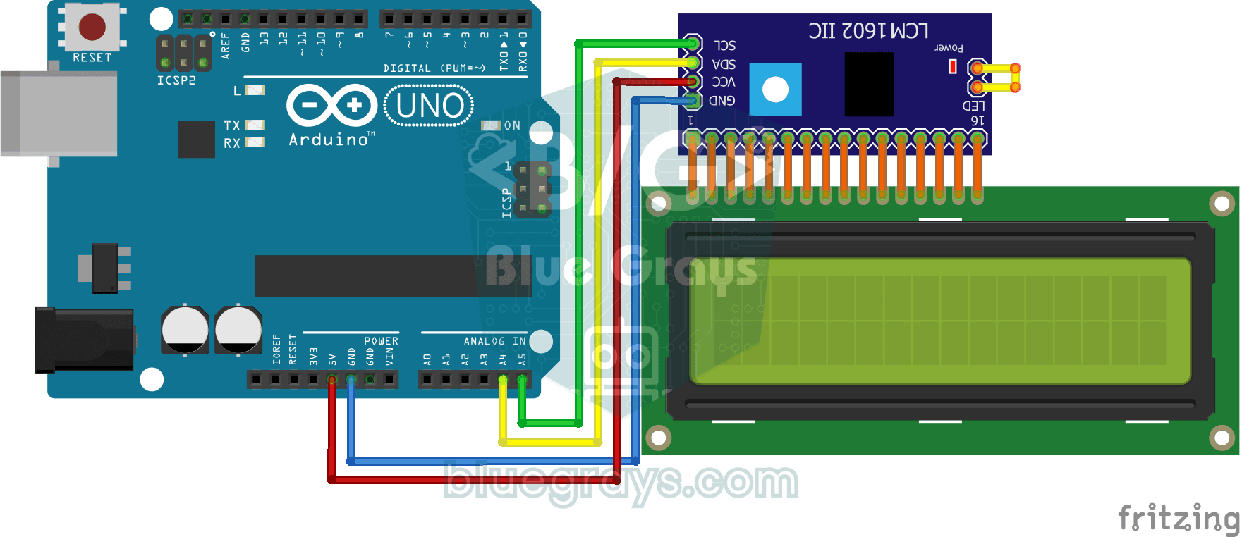
Using LCD Screen with I2C
Give your Arduino its own screen and make it write its first message. The two-line LCD screen hooks up with just a few wires; a greeting appears on the top line, then a second message on the bottom li