
Arduino Temperature Sensor Types: 8 Sensors Compared
Arduino temperature sensor types compared: DHT11, DHT22, DS18B20, LM35, NTC, BME280, MAX6675 and MLX90614 by accuracy, range, wiring, cable length and price.
Choosing among the different Arduino temperature sensor types matters more than it first seems: a DHT11 and a DS18B20 sitting in the same room can disagree by 2 °C, and it's entirely possible to melt a sensor by trying to measure a 300 °C oven with the wrong one. Eight temperature sensors dominate hobby electronics: DHT11, DHT22, DS18B20, LM35, the NTC thermistor, BME280, MAX6675 (type K thermocouple) and MLX90614 (non-contact infrared). Each comes with a different measuring range, accuracy, connection method and price. Which one is right depends on what you're measuring: room air, water, an oven, or a spinning motor you can't touch?
In this guide we put the eight sensors side by side in two big tables: measuring range, accuracy, resolution, reading speed, interface, supply voltage, cable length and relative price. Then you'll see how each one works, its strengths and weaknesses, the wiring for Arduino Uno, ESP32 and Raspberry Pi Pico, example code for the NTC, MAX6675 and MLX90614, a test rig that races three sensors against each other, and which one to choose for which project. We have detailed tutorials for most of these sensors too; you'll find the links in the relevant sections.
What should you look for when choosing a temperature sensor?
Before comparing sensors, you need to read the datasheet terms correctly. The pair people mix up most often is accuracy and resolution. Accuracy tells you how close your reading is to the real temperature; resolution is the smallest step the sensor can tell apart. The BME280 reports temperature in 0.01 °C steps, but its accuracy is around ±1 °C; so the last two digits of the 23.47 °C on your screen are useful for tracking small changes, but they don't tell you the real temperature that precisely. Look at these seven criteria when choosing:
- Measuring range: The sensor should comfortably cover the lowest and highest temperatures you want to measure. The DHT11 can't see below zero; a fridge needs a DS18B20 and an oven needs a thermocouple.
- Accuracy: ±2 °C is acceptable for a room thermometer, but an aquarium or an egg incubator needs ±0.5 °C.
- Interface: Analog sensors need an ADC pin; digital sensors need one or more digital pins and usually a library. The number of free pins on your board decides how many sensors you can connect.
- Cable length: If the sensor will sit 5 metres from the board, in the garden or at the bottom of a water tank, analog and I2C sensors struggle; 1-Wire and the DHT's single-wire protocol cope with long distances much better.
- Response time: A probe in a steel sleeve or a DHT in its plastic housing only catches a sudden temperature change after seconds or even minutes; a small bare NTC is far faster.
- Extra measurements: If you also need humidity, a DHT22 or BME280 does the job; if you need pressure and altitude too, the BME280 covers everything in one module.
- Supply voltage: On the 3.3 V ESP32 and Pico, watch out for sensors like the LM35 that need at least 4 V, and make sure no more than 3.3 V reaches the ADC input.
Comparison table of 8 temperature sensors
The first table summarises measuring performance, the second the wiring and cost side. Values come from the datasheets; unless stated otherwise, accuracy applies around room temperature and gets worse towards the ends of the range.
| Sensor | Measuring range | Accuracy | Resolution | Reading speed |
|---|---|---|---|---|
| DHT11 | 0 … +50 °C | ±2 °C | 1 °C | Once per second |
| DHT22 (AM2302) | −40 … +80 °C | ±0.5 °C | 0.1 °C | Once every 2 seconds |
| DS18B20 | −55 … +125 °C | ±0.5 °C (from −10 to +85 °C) | 0.0625 °C (12-bit) | 750 ms (12-bit), 94 ms (9-bit) |
| LM35DZ | 0 … +100 °C (LM35: −55 … +150 °C) | Typical ±0.6 °C, guaranteed ±1.5 °C | 0.49 °C on the Uno (5 V ref.), 0.11 °C (1.1 V ref.) | Instant (ADC speed) |
| NTC 10 kΩ, B 3950 | −40 … +125 °C (glass-encapsulated ≈ 300 °C) | At 25 °C: ±0.25 °C (1 %) … ±1 °C (5 %) | ≈ 0.1 °C at room temperature on the Uno | Instant (ADC speed) |
| BME280 | −40 … +85 °C | ±0.5 °C (25 °C), ±1 °C (0 … 65 °C) | 0.01 °C | Dozens per second |
| MAX6675 + type K thermocouple | 0 … +1023.75 °C | A few °C (converter ≈ ±2 °C, cold junction up to ±3 °C) | 0.25 °C | ≈ 4 per second (0.22 s conversion) |
| MLX90614 | Object −70 … +380 °C, ambient −40 … +125 °C | ±0.5 °C (around room temperature) | 0.02 °C | Several times per second |
| Sensor | Interface | Supply | Cable length | Extra measurement | Relative price |
|---|---|---|---|---|---|
| DHT11 | Single-wire digital, 1 pin | 3–5.5 V | Up to 20 m | Humidity | Very low |
| DHT22 | Single-wire digital, 1 pin | 3.3–6 V | Up to 20 m | Humidity | Medium |
| DS18B20 | 1-Wire, many sensors on 1 pin | 3.0–5.5 V | Tens of metres | None | Low |
| LM35 | Analog, 1 ADC pin | 4–30 V | Short, ≈ 1 m (longer needs precautions) | None | Low |
| NTC | Analog, 1 ADC pin via a divider | 3.3 or 5 V through the divider | A few metres | None | Lowest |
| BME280 | I2C (2 pins) or SPI | Chip 1.71–3.6 V; regulated module 5 V | Short, under 50 cm | Humidity and pressure | Medium |
| MAX6675 | SPI, 3 pins (read-only) | 3.0–5.5 V | Thermocouple wire can run for metres | None | Medium |
| MLX90614 | I2C (SMBus), 2 pins | 3 V or 5 V version (module may have a regulator) | Short (I2C); measures without contact | Ambient temperature | High |
DHT11 and DHT22: temperature and humidity together
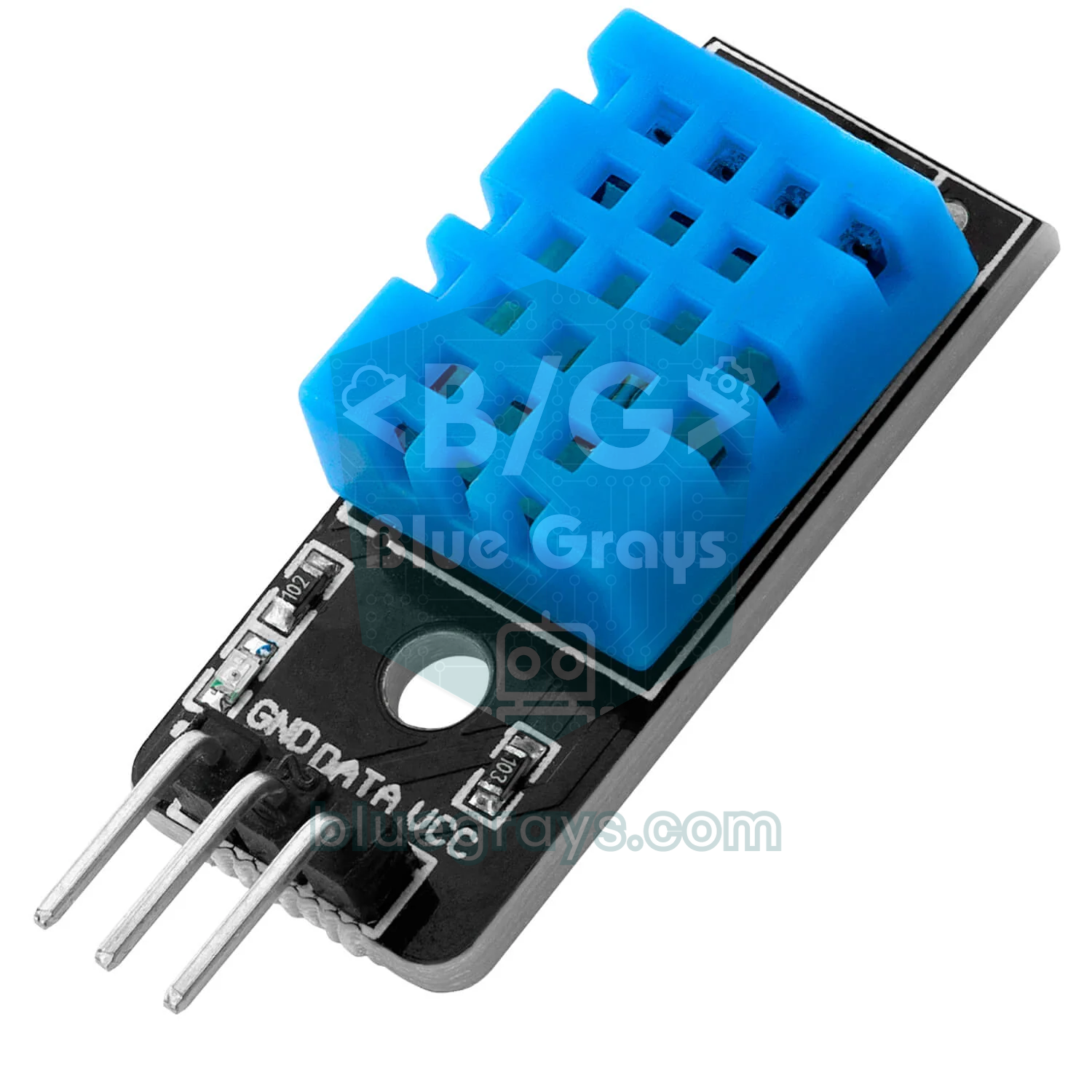
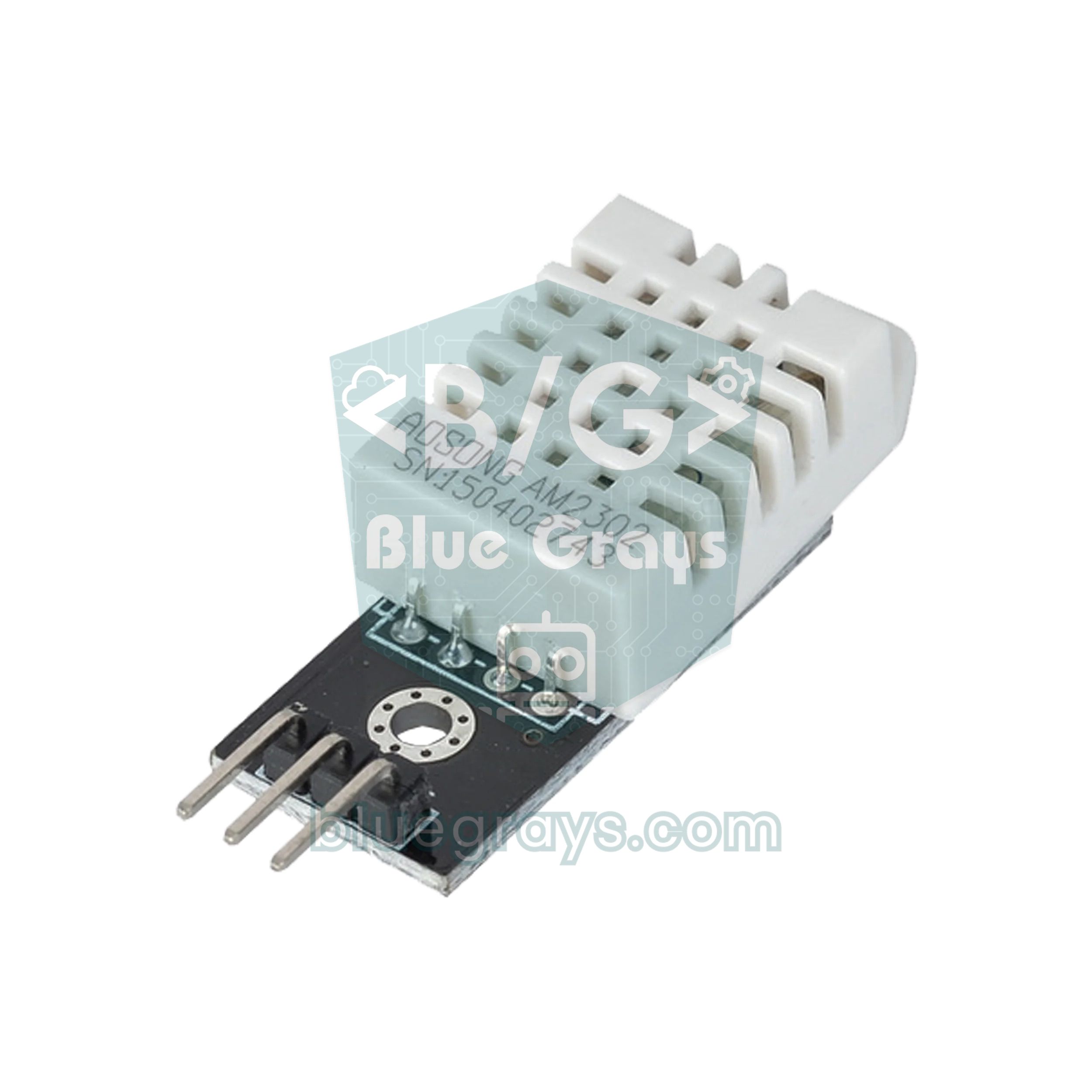
Inside the plastic cage of a DHT sensor there's a humidity element (resistive in the DHT11, capacitive in the DHT22), a thermistor and a small controller that turns the readings into digital data. The sensor sends its result over a single data line as a 40-bit packet: 16 bits of humidity, 16 bits of temperature and an 8-bit checksum. This protocol isn't 1-Wire but the manufacturer's own single-wire protocol, so every DHT needs its own pin. The DHT11 is cheap and good enough for room temperature, but its 0–50 °C range and ±2 °C error make it weak for outdoor use and precise work. With the same wiring, the DHT22 (AM2302) measures from −40 to +80 °C with ±0.5 °C accuracy and reports humidity over 0–100 %; in return it can only take one reading every two seconds. Both share one weakness, slowness: they show a change late, because the air inside the cage first has to reach equilibrium with its surroundings. For wiring, library installation and code, see DHT11 Temperature and Humidity Sensor; the same code works for the DHT22 by changing a single word.
DS18B20: waterproof, rugged and many sensors on one pin
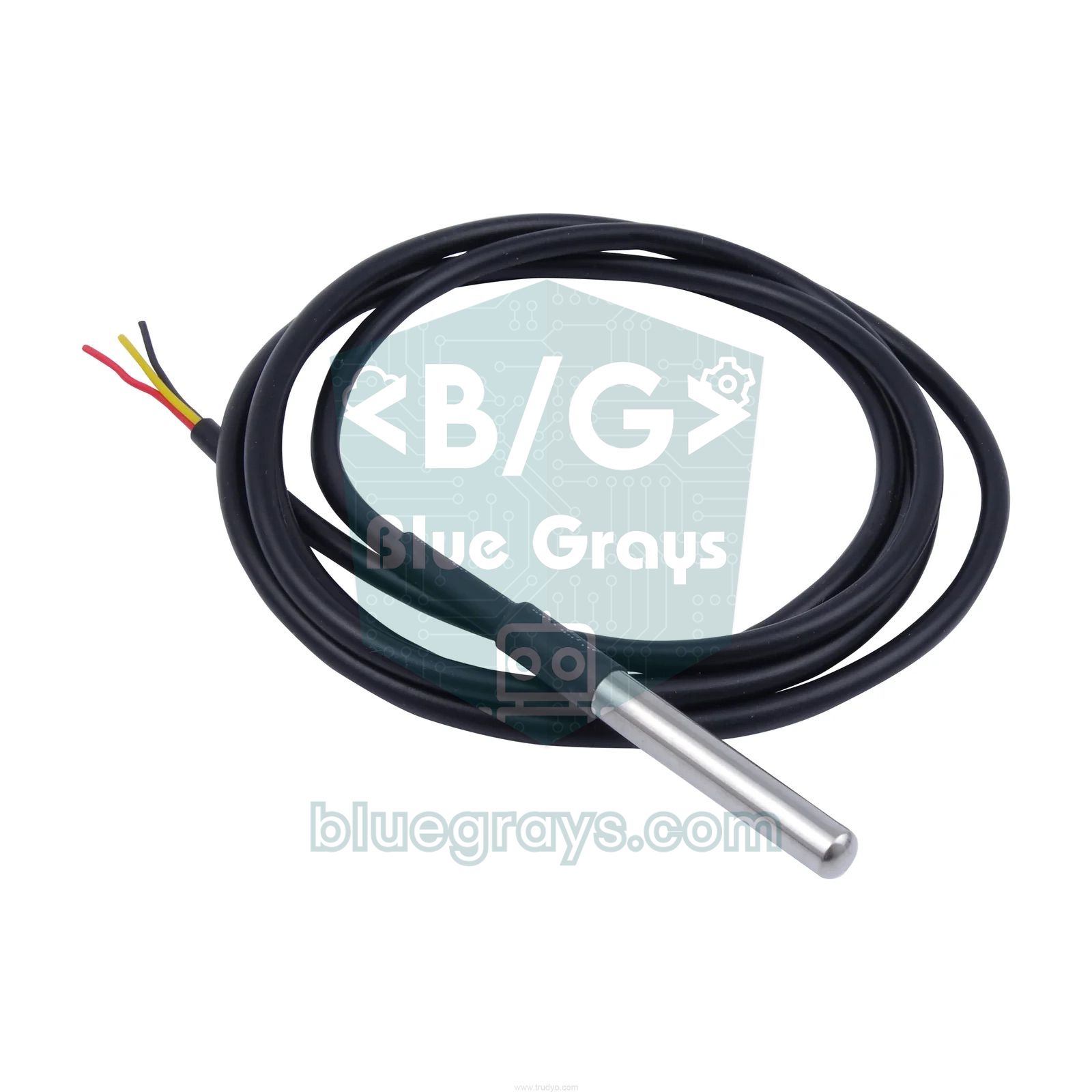
The DS18B20 measures temperature inside the chip and sends it as a digital number with a selectable 9- to 12-bit resolution. It measures from −55 to +125 °C, offers ±0.5 °C accuracy from −10 to +85 °C, and thanks to the 1-Wire protocol you can connect dozens of sensors to a single data pin; each one has a unique 64-bit address written at the factory. Its waterproof probe version in a stainless steel sleeve is unbeatable for aquariums, water tanks, heating pipes, soil and freezers. Its only requirement is a 4.7 kΩ pull-up resistor between the data line and the supply; without it, the library returns −127 °C. In 12-bit mode one conversion takes 750 ms, so you may need to lower the resolution to follow a fast-changing temperature. The multi-sensor code and how to read it on the ESP32 without blocking are in DS18B20 Temperature Sensor.
LM35: the simplest analog sensor, no library needed
The LM35 turns temperature straight into a voltage: its output rises by 10 mV per degree and gives 250 mV at 25 °C. No library is needed; you get the result with the formula temperature = analogRead × 5.0 / 1024 × 100. That simplicity makes it a perfect first step for learning the ADC. Its weaknesses come from the same place: with a 5 V reference, the Arduino Uno's 10-bit ADC only gives steps of about 0.49 °C, every deviation in the 5 V from USB goes straight into the temperature, and the longer the cable, the more noise the output picks up. Most LM35s on the market are LM35DZ parts, guaranteed only for 0–100 °C. It also needs at least 4 V, so on the ESP32 and Pico it should be powered from the 5 V pin. On 3.3 V boards a more practical analog option is the TMP36: it runs from 2.7–5.5 V, measures −40 to +125 °C and also outputs 10 mV/°C, but because it gives 500 mV at 0 °C the formula becomes temperature = (V − 0.5) × 100. Its typical accuracy is ±1 °C at 25 °C and ±2 °C across the full range. We explain step by step how to shrink the step to 0.11 °C with the 1.1 V internal reference in LM35 Temperature Sensor, and you'll find how the ADC works in analog-to-digital conversion.
NTC thermistor: the cheapest and fastest sensor
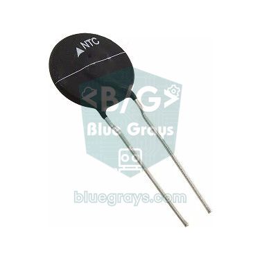
An NTC (Negative Temperature Coefficient) thermistor is a resistor whose resistance falls as the temperature rises. The most common type in hobby projects is 10 kΩ at 25 °C with a B coefficient of 3950 K. Since the Arduino can't measure resistance directly, the NTC is wired as a voltage divider together with a fixed resistor, and the voltage at the midpoint is read on an analog pin. This circuit has a nice property: when the divider is powered from the same 5 V as the ADC reference, the measurement is ratiometric, so the result doesn't change even if the supply is 4.8 or 5.1 V. You can easily work out the divider voltages with the voltage divider tool.
An NTC's resistance changes with temperature exponentially, not linearly, so you can't get the result with a single multiplier as with the LM35. In practice you use the Beta equation: 1/T = 1/T0 + (1/B) × ln(R/R0). Here T is the temperature in kelvin, T0 = 298.15 K (25 °C), R0 = 10 kΩ and B = 3950. Sensitivity is very high at room temperature: according to the formula B/T², the resistance changes by about 4.4 % per degree. That's why an NTC with 1 % tolerance is only off by around ±0.25 °C at 25 °C; towards the ends of the range, though, the tolerance of the B coefficient comes into play and the error grows. For better accuracy over a wide range, the three-point Steinhart-Hart equation is used; details are in NTC thermistor.
1const int NTC_PIN = A1;          // bölücünün orta noktası / divider midpoint
2const float R_FIXED = 10000.0;   // 5V ile A1 arasındaki direnç / resistor between 5V and A1
3const float R0 = 10000.0;        // NTC'nin 25 °C'deki direnci / NTC resistance at 25 °C
4const float BETA = 3950.0;       // B katsayısı (veri sayfası) / B coefficient (datasheet)
5const float T0 = 298.15;         // 25 °C Kelvin cinsinden / 25 °C in kelvin
6const int SAMPLES = 16;          // ortalama için ölçüm sayısı / samples to average
7
8void setup() {
9  Serial.begin(9600);
10}
11
12void loop() {
13  long sum = 0;
14  for (int i = 0; i < SAMPLES; i++) {
15    sum += analogRead(NTC_PIN);
16    delay(2);
17  }
18  float adc = sum / (float)SAMPLES;
19
20  if (adc < 1.0 || adc > 1022.0) {                    // kopuk ya da kısa devre / open or shorted
21    Serial.println(F("NTC baglantisini kontrol et / Check the NTC wiring"));
22    delay(1000);
23    return;
24  }
25
26  float r = R_FIXED * adc / (1023.0 - adc);           // NTC direnci (ohm) / NTC resistance (ohm)
27  float invT = 1.0 / T0 + log(r / R0) / BETA;         // Beta denklemi / Beta equation
28  float tempC = 1.0 / invT - 273.15;                  // Kelvin -> °C
29
30  Serial.print(F("R: "));
31  Serial.print(r, 0);
32  Serial.print(F(" ohm  Sicaklik / Temp: "));
33  Serial.print(tempC, 1);
34  Serial.println(F(" C"));
35  delay(1000);
36}
In this circuit the 10 kΩ fixed resistor sits between 5V and A1, and the NTC between A1 and GND. As the temperature rises, the NTC's resistance, and with it the voltage at A1, drops. The code first works out the NTC's resistance from the raw value, then the temperature in kelvin with the Beta equation, and converts it to Celsius; averaging 16 readings cuts the ADC noise to a quarter. At room temperature one ADC step on the Uno corresponds to about 0.09 °C, so the resolution is five times better than an LM35 read with the 5 V reference. On ready-made NTC modules (the KY-013, for example) the side the fixed resistor sits on varies from board to board; if the reading drops when you touch the NTC with something warm, flip the resistance formula: r = R_FIXED × (1023 − adc) / adc.
BME280: temperature, humidity and pressure in one module
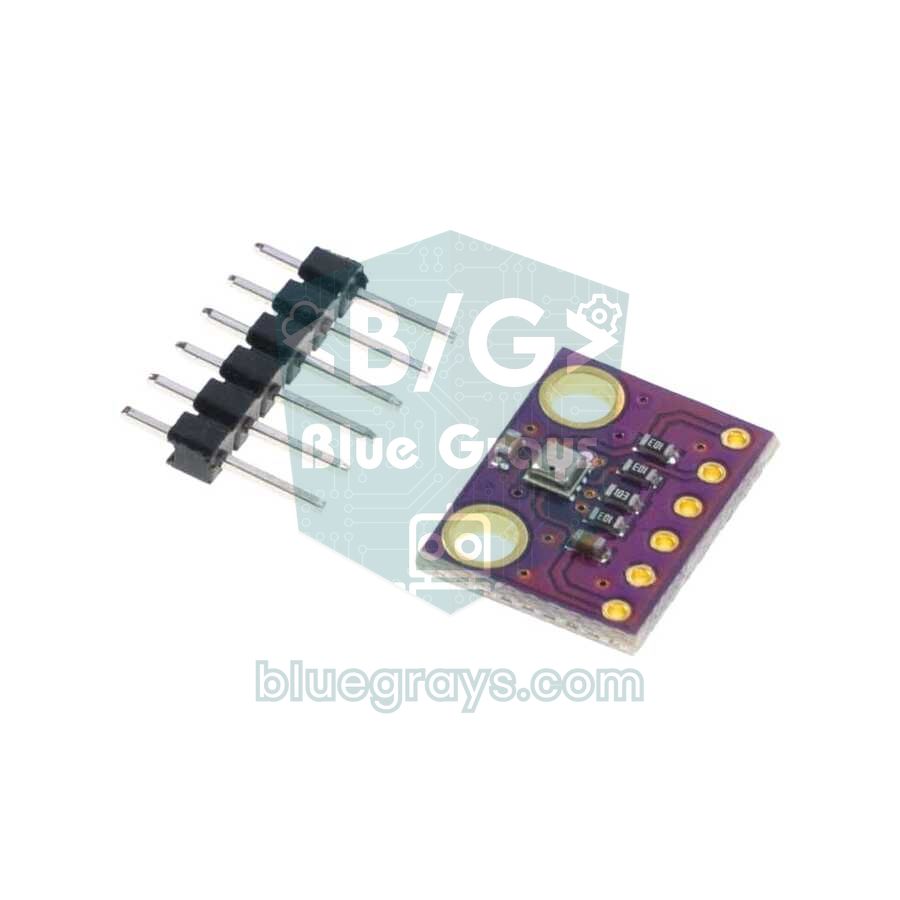
Bosch's BME280 measures temperature, relative humidity and air pressure on a chip just 2.5 × 2.5 mm in size, and talks over I2C (address 0x76 or 0x77) or SPI. For temperature it offers 0.01 °C resolution and an accuracy of ±0.5 °C at 25 °C and ±1 °C from 0 to 65 °C; it can take dozens of readings per second and draws far less than 1 µA in sleep. That makes it ideal for battery-powered weather stations. The chip itself can't take more than 3.6 V: 6-pin purple modules are usually 3.3 V only, while 4-pin modules with a regulator can be connected to 5 V. When it measures continuously, the chip warms up slightly and may read a few tenths of a degree high; for weather measurements, forced mode with a few readings per minute is enough. We explain how the I2C bus works in What is I2C?.
MAX6675 and type K thermocouple: up to 1000 °C
A thermocouple is made of two wires of different metals welded together at one end. The temperature difference between the weld (the hot junction) and the point where the wires connect to the device (the cold junction) produces a tiny voltage in the wires; for a type K thermocouple it's about 41 µV per degree. The Arduino's ADC can't read a voltage that small, and you also need to know the temperature of the cold junction. The MAX6675 does both jobs at once: it amplifies the thermocouple voltage, applies cold-junction compensation by measuring its own temperature, and delivers the result over SPI with 12-bit, 0.25 °C resolution. Its range is 0 to +1023.75 °C, which makes it the only option here for places the other sensors can't survive, such as a soldering iron, pizza oven, barbecue, kiln or exhaust.
You should know the MAX6675's limits too: it can't measure below 0 °C; the converter's own error is about ±2 °C between 0 and 700 °C, and on top of that come the cold-junction compensation error of up to ±3 °C and the tolerance of the thermocouple wire. So expect an overall accuracy of a few degrees; in an 800 °C oven that difference doesn't matter. One conversion takes 0.17–0.22 seconds, so wait at least 250 ms between two readings. If you also need negative temperatures, the newer MAX31855 (−200 to +1350 °C, 14-bit) is the better choice. You'll find how the SPI bus works in What is SPI?. After installing Adafruit's MAX6675 library from the Library Manager in the Arduino IDE, upload the code below:
1#include "max6675.h"
2
3const int thermoDO  = 4;    // SO: veri çıkışı / data out
4const int thermoCS  = 5;    // CS: çip seçimi / chip select
5const int thermoCLK = 6;    // SCK: saat / clock
6
7MAX6675 thermocouple(thermoCLK, thermoCS, thermoDO);
8
9void setup() {
10  Serial.begin(9600);
11  delay(500);                                   // ilk ölçümü bekle / wait for the first conversion
12}
13
14void loop() {
15  float c = thermocouple.readCelsius();
16  if (isnan(c)) {                               // D2 biti: termokupl açık / bit D2: thermocouple open
17    Serial.println(F("Termokupl takili degil / Thermocouple not connected"));
18  } else {
19    Serial.print(F("Sicaklik / Temp: "));
20    Serial.print(c, 2);
21    Serial.println(F(" C"));
22  }
23  delay(500);                                   // en az 250 ms bekle / wait at least 250 ms
24}MLX90614: measuring temperature without contact
The MLX90614 is a non-contact temperature sensor that detects the infrared radiation emitted by objects with a thermopile. It gives two values at once: the ambient temperature, which is the temperature of its own body (−40 to +125 °C), and the object temperature, which is the temperature of the surface it's looking at (−70 to +380 °C). Around room temperature it offers ±0.5 °C accuracy and 0.02 °C resolution; it's factory-calibrated and talks over I2C (SMBus) at address 0x5A, and the bus speed must not exceed 100 kHz. It's ideal for measuring a spinning motor, a bearing, a hot chip on a circuit board or a pan on the stove without touching them.
Non-contact measurement has two tricks to it. The first is the field of view: the sensor measures the average of everything inside its viewing cone. The most common version, the MLX90614ESF-BAA, has a 90° field of view; that means at 5 cm away it averages an area about 10 cm across. To measure a small object, move the sensor closer or choose a narrow-angle version such as 35° (BCC) or 5° (BCI). The second is emissivity: the sensor is set to 1.0 at the factory. For matte paint, plastic, wood, skin and water the coefficient is between 0.9 and 0.98, so the result is close to correct; shiny metal surfaces, however, emit very little radiation and look much colder than they are. Sticking a piece of matte black tape on them is a simple and effective fix. Install the Adafruit MLX90614 library from the Library Manager and try this code:
1#include <Wire.h>
2#include <Adafruit_MLX90614.h>
3
4Adafruit_MLX90614 mlx = Adafruit_MLX90614();
5
6void setup() {
7  Serial.begin(9600);
8  if (!mlx.begin()) {                           // varsayılan adres 0x5A / default address 0x5A
9    Serial.println(F("MLX90614 bulunamadi / not found"));
10    while (true) delay(10);
11  }
12  Serial.print(F("Emisivite / Emissivity: "));
13  Serial.println(mlx.readEmissivity(), 2);      // fabrika ayarı 1.00 / factory default 1.00
14}
15
16void loop() {
17  Serial.print(F("Ortam / Ambient: "));
18  Serial.print(mlx.readAmbientTempC(), 2);      // sensör gövdesi / sensor body
19  Serial.print(F(" C   Nesne / Object: "));
20  Serial.print(mlx.readObjectTempC(), 2);       // baktığı yüzey / surface in view
21  Serial.println(F(" C"));
22  delay(500);
23}Wiring summary: Arduino Uno, ESP32 and Raspberry Pi Pico
| Sensor and pin | Arduino Uno | ESP32 | Raspberry Pi Pico |
|---|---|---|---|
| DHT11 / DHT22: DATA | D2 | GPIO 27 | GP15 |
| DS18B20: DQ (+ 4.7 kΩ pull-up) | D3 | GPIO 4 | GP22 |
| LM35: Vout (5 V supply) | A0 | GPIO 34 (ADC1) | GP26 (ADC0) |
| NTC: divider midpoint | A1 (divider from 5V) | GPIO 35 (ADC1, divider from 3V3) | GP27 (ADC1, divider from 3V3) |
| BME280: SDA / SCL | A4 / A5 | GPIO 21 / 22 | GP4 / GP5 |
| MLX90614: SDA / SCL | A4 / A5 (same I2C bus) | GPIO 21 / 22 | GP4 / GP5 |
| MAX6675: SO / CS / SCK | D4 / D5 / D6 | GPIO 19 / 23 / 18 | GP16 / GP17 / GP18 |
| Supply (VCC) | 5V (3.3V for the 6-pin BME280) | 3V3 (5V/VIN for the LM35) | 3V3(OUT) (VBUS for the LM35) |
The ESP32 and Pico run on 3.3 V; if you power the NTC divider from 3V3, no unsafe voltage can reach the ADC input. On the ESP32, connect analog sensors only to ADC1 pins (GPIO 32–39), because the ADC2 pins don't work while Wi-Fi is on; for bidirectional data lines like the DHT and DS18B20, on the other hand, avoid GPIO 34–39, as these pins are input-only. The BME280 (0x76) and MLX90614 (0x5A) have different addresses, so they can happily share the same two I2C wires. You'll find all of your board's pins in the Pinout tool and the colour codes of the pull-up resistors in the resistor colour code tool.
Comparison test with the ESP32: three sensors in the same spot
The best way to see the differences between sensors is with your own eyes. The ESP32 code below reads a DS18B20, a DHT22 and a BME280 at the same time and shows the results as three separate lines in the Arduino IDE's Serial Plotter. Place the sensors side by side on the breadboard, at least 10 cm from the ESP32; the ESP32 warms up while running and affects any sensor next to it. The code needs the OneWire, DallasTemperature, DHT sensor library and Adafruit BME280 libraries.
1#include <OneWire.h>
2#include <DallasTemperature.h>
3#include <DHT.h>
4#include <Wire.h>
5#include <Adafruit_Sensor.h>
6#include <Adafruit_BME280.h>
7
8const int ONE_WIRE_PIN = 4;     // DS18B20 DQ (4,7 kΩ pull-up -> 3V3)
9const int DHT_PIN = 27;         // DHT22 DATA
10
11OneWire oneWire(ONE_WIRE_PIN);
12DallasTemperature ds(&oneWire);
13DHT dht(DHT_PIN, DHT22);
14Adafruit_BME280 bme;            // I2C: SDA GPIO 21, SCL GPIO 22
15bool bmeOk = false;
16
17void setup() {
18  Serial.begin(115200);
19  ds.begin();
20  dht.begin();
21  bmeOk = bme.begin(0x76) || bme.begin(0x77);   // iki adresi de dene / try both addresses
22  if (!bmeOk) Serial.println("BME280 bulunamadi / not found");
23}
24
25void loop() {
26  ds.requestTemperatures();                     // 12 bitte ~750 ms sürer / takes ~750 ms at 12-bit
27  float tDs  = ds.getTempCByIndex(0);           // sensör yoksa -127 / -127 if missing
28  float tDht = dht.readTemperature();           // hata olursa NAN / NAN on error
29  float tBme = bmeOk ? bme.readTemperature() : NAN;
30
31  // Seri Çizici için etiket:değer biçimi / label:value format for the Serial Plotter
32  Serial.printf("DS18B20:%.2f,DHT22:%.1f,BME280:%.2f\n", tDs, tDht, tBme);
33  delay(2000);                                  // DHT22 en fazla 2 sn'de bir / DHT22 at most every 2 s
34}
First wait a few minutes and see how far apart the lines sit: differences of 0.5–1 °C are within these sensors' accuracy limits. Then place a glass of warm water next to them or gently blow on all three. The DS18B20 and BME280 react within a few seconds, while the DHT22's line clearly lags behind because of its plastic cage. If the BME280 constantly stays a few tenths of a degree above the others, that's the chip heating itself. This little experiment shows you differences that aren't written in any datasheet. To log readings over a long time, you can use an SD card module or send the data to Google Sheets.
Measuring temperature with the Raspberry Pi Pico and MicroPython
The Pico's MicroPython firmware comes with the dht, onewire and ds18x20 modules built in, so you don't need to copy any extra files to the Pico for the DHT and DS18B20. The RP2040 chip also has an internal temperature sensor connected to channel 4 of the ADC. The code below reads all three together:
1from machine import Pin, ADC
2import dht, onewire, ds18x20, time
3
4dht22 = dht.DHT22(Pin(15))                          # DHT22 DATA -> GP15
5ds = ds18x20.DS18X20(onewire.OneWire(Pin(22)))      # DS18B20 DQ -> GP22 (4,7 kΩ pull-up)
6roms = ds.scan()                                    # hattaki sensörler / sensors on the bus
7cpu = ADC(4)                                        # RP2040 dahili sensörü / internal sensor
8
9def cpu_temp():
10    v = cpu.read_u16() * 3.3 / 65535                # ham değer -> volt / raw value -> volts
11    return 27 - (v - 0.706) / 0.001721              # RP2040 veri sayfası formülü / datasheet formula
12
13while True:
14    t_ds = None
15    if roms:
16        ds.convert_temp()                           # ölçümü başlat / start conversion
17        time.sleep_ms(750)                          # 12 bit dönüşüm süresi / 12-bit conversion time
18        t_ds = round(ds.read_temp(roms[0]), 2)
19    try:
20        dht22.measure()
21        t_dht, nem = dht22.temperature(), dht22.humidity()
22    except OSError:                                 # okuma hatası / read error
23        t_dht = nem = None
24    print("DS18B20:", t_ds, "DHT22:", t_dht, "Nem / RH:", nem,
25          "Pico:", round(cpu_temp(), 1))
26    time.sleep(2)
The internal sensor measures the chip's temperature, not the room's, and small deviations in the ADC reference can shift the result by a few degrees. So it's not meant for measuring the environment, but it's handy for checking whether the board is overheating. Don't forget the 4.7 kΩ pull-up on the DS18B20's data line; the Pico's internal pull-up resistors are too weak for 1-Wire. If you're new to the Pico, start with What is the Raspberry Pi Pico?.
Which temperature sensor for which project?
| Project or need | Recommended sensor | Why? |
|---|---|---|
| First project, room thermometer | DHT11 | The cheapest, also gives humidity; ±2 °C is enough for a room |
| Indoor and outdoor weather station | BME280 or DHT22 | Goes down to −40 °C and gives humidity; the BME280 also measures pressure and altitude |
| Aquarium, water tank, boiler water | DS18B20 waterproof probe | Stainless sleeve, ±0.5 °C, long cable |
| Fridge and freezer | DS18B20 | Measures down to −55 °C; the DHT11 can't see below zero |
| Measuring many points (rooms, greenhouse, pipes) | DS18B20 | Dozens of sensors on one pin, each with its own address |
| Egg incubator | DHT22 or BME280 | ±0.5 °C around 37.5 °C plus humidity control |
| Oven, barbecue, soldering iron | MAX6675 + type K thermocouple | Withstands up to 1000 °C |
| 3D printer hotend, battery pack | NTC thermistor | Small, cheap and fast; 3D printers use 100 kΩ glass-encapsulated NTCs |
| Motor, bearing, circuit board, moving part | MLX90614 | Measures without contact |
| Learning the ADC and analog measurement | LM35 or NTC | No library needed, works with a formula |
Project ideas with temperature sensors
- Smart greenhouse: Measure air temperature and humidity with a DHT22 and soil temperature with a DS18B20 probe; control the fan and watering with a relay module. For the complete project, see the smart greenhouse project.
- Aquarium heater with thermostat: Keep the water between 25 and 26 °C with a waterproof DS18B20; use 0.5 °C of hysteresis so the relay doesn't switch on and off at every tiny change.
- Battery-powered weather station: Combine a BME280 with the ESP32's deep sleep mode and measure every ten minutes so the system runs for months on batteries.
- Pizza oven or barbecue thermometer: Show the oven temperature in big digits on an OLED display with a MAX6675 and a type K probe.
- Non-contact motor temperature alarm: Monitor the surface temperature of a motor or a 3D printer bed with an MLX90614 and sound a buzzer when it passes a threshold.
- Home automation: Send the temperature of every room to Home Assistant over MQTT with an ESP32 and control the heating accordingly.
- Freezer guard: With a DS18B20, sound an alarm if the inside of the freezer rises above −12 °C and show the value on an I2C LCD display.
Common mistakes and how to fix them
| Symptom | Likely cause | Fix |
|---|---|---|
| DHT: nan or "Failed to read from DHT sensor!" | Wrong type in the code (DHT11/DHT22), no pull-up or reading too often | Fix the type, add a 10 kΩ pull-up, wait 2 seconds between readings |
| DS18B20: −127 °C | Sensor not found: no pull-up, faulty cable or wrong pin | Fit 4.7 kΩ between DQ and VCC, check the connections |
| DS18B20: always 85 °C | Read before the conversion finished, or insufficient supply | Wait for the conversion time, power VDD directly |
| LM35: abnormally high value, sensor getting hot | Supply pins connected the wrong way round | Cut the power at once and fix the pin order |
| LM35 or NTC: value keeps jumping | ADC noise, long cable, fluctuating USB supply | Average readings, add a 0.1 µF capacitor, shorten the cable |
| NTC: temperature drops as it warms up | Divider orientation doesn't match the code | Flip the resistance formula |
| BME280: "Could not find a valid BME280 sensor" | Wrong address (0x76/0x77) or the chip is really a BMP280 | Change the address, read the chip ID (0x60 / 0x58) |
| BME280 or DHT: 1–3 °C too high | Self-heating, a nearby ESP32 or regulator | Move the sensor away from the board, read less often, apply an offset |
| MAX6675: nan | Thermocouple not connected or wire broken | Check the screw terminals and the probe |
| MAX6675: value drops as it heats up | Thermocouple polarity reversed | Swap the + and − leads |
| MLX90614: shiny metal looks very cold | Low emissivity | Stick on matte black tape or set the emissivity |
| MLX90614: small object measured wrongly | Field of view bigger than the object | Move the sensor closer or use a narrow-angle version |
In short: a DHT22 or BME280 for rooms and weather, a DS18B20 for water and cold places, an LM35 or NTC for learning analog measurement and fast response, a MAX6675 for high temperatures and an MLX90614 for surfaces you can't touch are the right starting points. If you'd like to get to know other kinds of sensors as well, have a look at the Arduino sensors guide. In the BlueGrays app you'll find step-by-step circuit diagrams and code for projects such as temperature and humidity measurement with the DHT11, a thermometer with an NTC and LCD, a temperature display with an ESP32, DHT22 and LCD, an ESP32 temperature logger and smart irrigation.
Frequently asked questions
Which is the most accurate temperature sensor for Arduino?
Among hobby sensors, the most accurate options around room temperature are the DS18B20, DHT22, BME280 (at 25 °C) and MLX90614, all at ±0.5 °C. The DS18B20 stands out for wired and waterproof measurements, the DHT22 or BME280 when you also need humidity. Whichever you choose, comparing the sensor once with a reliable thermometer and correcting the offset in code improves accuracy noticeably.
Should I buy a DHT11 or a DHT22?
If you only want to roughly monitor room temperature and humidity, a DHT11 is enough. If you need outdoor use, sub-zero temperatures or ±0.5 °C accuracy, get a DHT22; it measures from −40 to +80 °C and gives more accurate humidity too. Both work with the same library and code; you only change the sensor type in the sketch.
How do I measure water temperature with Arduino?
The best sensor for water is the waterproof DS18B20 probe in a stainless steel sleeve. You dip the probe in the water and connect the data wire to a digital pin of the Arduino with a 4.7 kΩ pull-up resistor. The cable and its joints usually aren't designed to stay in hot water for long, so only put the steel tip in the water.
Can Arduino measure high temperatures like 500 °C?
Yes. With a type K thermocouple and a MAX6675 module you can measure from 0 to about 1024 °C. The thermocouple tip goes inside the oven, while the MAX6675 module must stay away from the heat. Always check what temperature the sheath and cable of the probe you bought are rated for.
Can you build a non-contact thermometer with Arduino?
You can build a non-contact infrared thermometer connected to an Arduino with an MLX90614; the standard version offers ±0.5 °C accuracy around room temperature. Body temperature needs the medical-accuracy version (±0.2 °C) and the right measuring distance, and even then this setup doesn't replace a medical device. When measuring, make sure the target surface completely fills the sensor's field of view.
Why does my temperature sensor read too high?
The most common reason is a heat source near the sensor: an ESP32, a voltage regulator or sunlight. Sensors like the BME280 also warm themselves slightly when they measure continuously. Move the sensor 10–15 cm away from the board, read it less often and correct the remaining constant difference in your code by comparing it with a thermometer you trust.
Projects to build after reading this
See all projects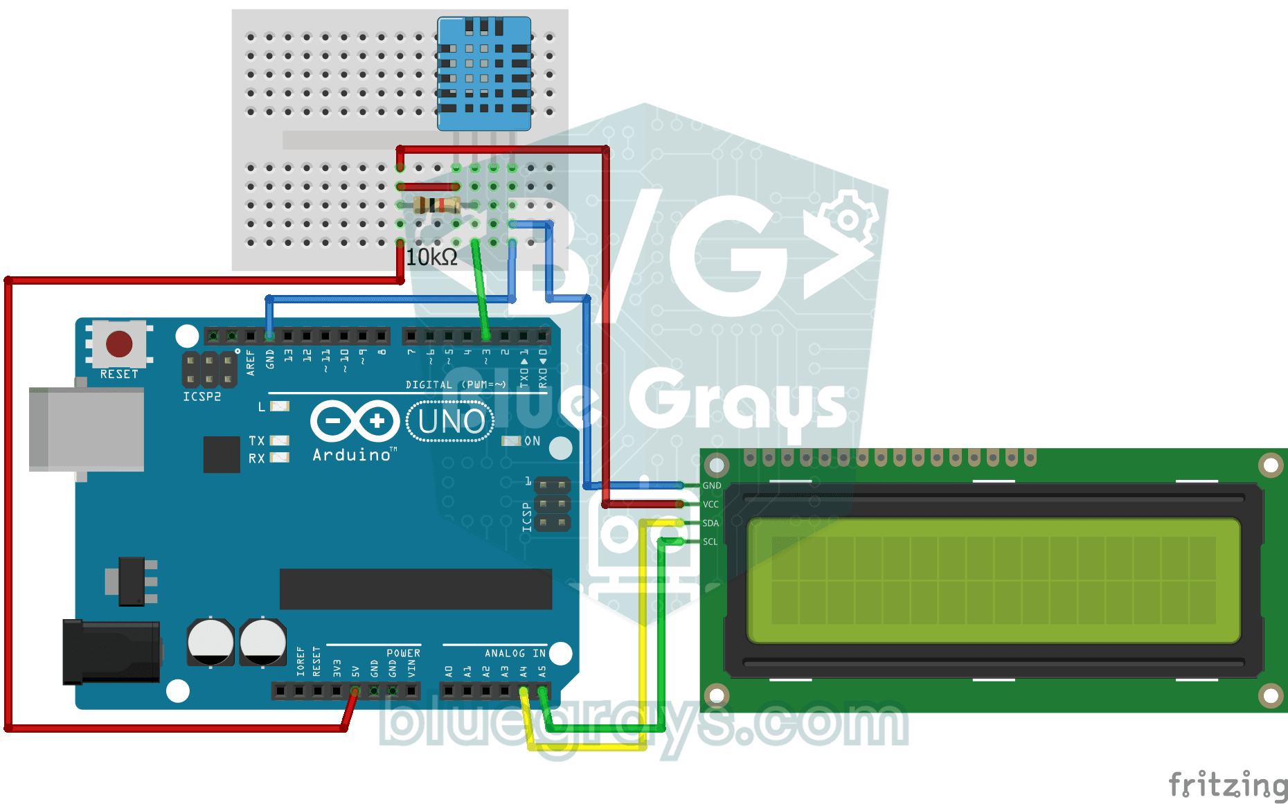
Temperature and Humidity with DHT11
How warm is your room, and is the air humid or dry? The DHT11 sensor measures temperature and humidity, and the Arduino writes the values on a two-line LCD screen, refreshing every couple of seconds.
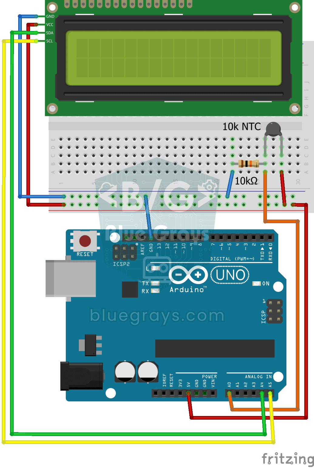
Temperature Measurement with NTC and 2x16 Lcd Display
Measure the temperature around you with a sensor that looks like a tiny bead. This part, called an NTC, lets electricity through more easily as it warms up; the Arduino reads that change, turns it int

ESP32 DHT22 Temperature and Humidity (with LCD Display)
This project measures ambient temperature and humidity using a DHT22 sensor and displays the data in real time on a 16x2 I2C LCD. Data is read from the sensor using the one-wire protocol via the Adafruit DHT library. This project serves as the foundation for IoT weather stations, smart home automation, or environmental monitoring systems in greenhouses. Communication with the DHT22 is established via the ESP32's GPIO 4 pin.
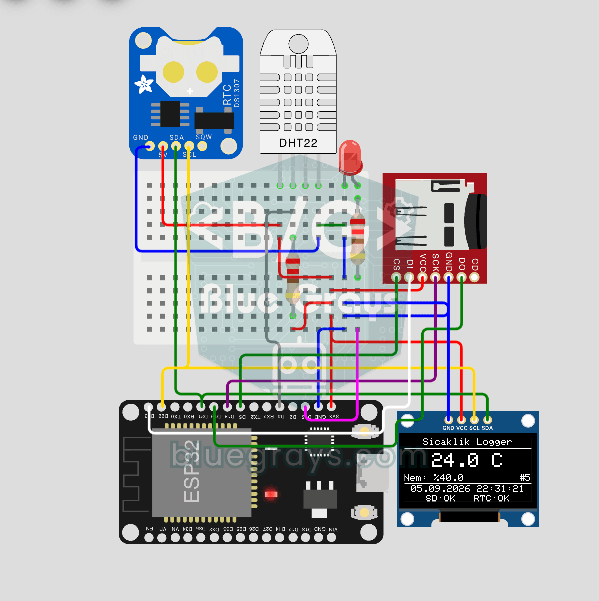
ESP32 Temperature Data Logger (DHT22 + DS1307 RTC + microSD + OLED)
Build a timestamped temperature logger with ESP32! Read DHT22 temperature/humidity every minute, get real-world time from DS1307 RTC, and log to microSD card as CSV. The OLED displays live temperature (large font), humidity percentage, timestamp, and log counter. The /temp_log.csv file on the SD card opens in Excel, Google Sheets, or Python pandas for analysis — perfect for greenhouse monitoring, home/room temperature tracking, laboratory data collection, food storage conditions, or beehiv

Dot Matrix Clock, Calendar and Weather Station (MAX7219, DS1307)
A scrolling-text board for your desk or wall that shows the time, the date and the room's weather in turn. On the 8x32 LED display you first see the temperature in both Celsius and Fahrenheit, then th

Smart Irrigation Station
A gardener that waters your plants on its own, so they don't dry out while you're on vacation. A soil moisture sensor measures how wet the soil is; when it gets dry, the Arduino runs the water pump fo
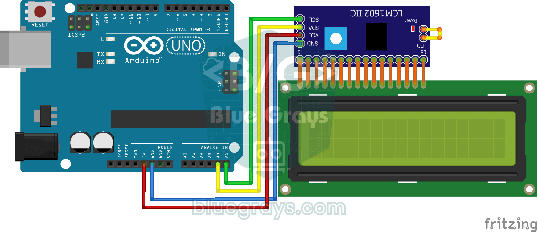
Using LCD Screen with I2C
Give your Arduino its own screen and make it write its first message. The two-line LCD screen hooks up with just a few wires; a greeting appears on the top line, then a second message on the bottom li