
MQ-7 Carbon Monoxide Sensor: CO Detection and Alarm with Arduino
How do you use the MQ-7 CO sensor? The 5 V / 1.4 V heater cycle, warm-up, ppm calculation, calibration and a buzzer CO alarm with Uno, ESP32 and Pico.

The MQ-7 carbon monoxide sensor is a cheap semiconductor gas sensor based on tin dioxide (SnO2) that detects carbon monoxide (CO) in the air. According to the manufacturer's datasheet it responds to CO in the range of roughly 20–2000 ppm, and you read it as a simple analog voltage with an Arduino, ESP32 or Raspberry Pi Pico. What sets it apart from other MQ sensors is that its heater must not run at a constant voltage; it has to be cycled with 60 seconds at 5 V and 90 seconds at 1.4 V. In this post you'll see step by step how to build that cycle with a MOSFET and PWM, calculate ppm from the measured voltage, calibrate in clean air, and build a buzzer CO alarm for a room with a stove or boiler on three platforms.
Carbon monoxide is a colourless, odourless and tasteless gas; it binds to haemoglobin in the blood about 200 times more strongly than oxygen does. That's why poisoning creeps up on you: first a headache and drowsiness, then nausea and confusion. Every winter we read news of poisonings caused by poorly burning stoves, boilers with blocked flues and water heaters running in enclosed spaces. That makes the MQ-7 a very instructive component, both for learning how gas sensors work and for understanding a real-world problem.
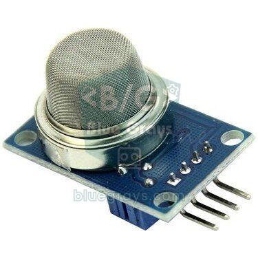
What is the MQ-7 and how does it work?
Under the sensor's metal mesh cap there is a small ceramic tube coated with tin dioxide and a thin wire that heats it. The heated SnO2 surface adsorbs oxygen from the air, and in this state its electrical resistance is high. If a reducing gas such as CO is present, it reacts with the oxygen on the surface, and the freed electrons lower the resistance of the layer. In other words, as CO increases, the sensor resistance (Rs) decreases. When you connect this resistance in series with a load resistor (RL) and measure the voltage in the middle, you've actually built a voltage divider and you read the CO level as an analog value.
| Feature | Value |
|---|---|
| Detected gas | Carbon monoxide (CO); also responds to hydrogen and alcohol |
| Measuring range | 20–2000 ppm CO |
| Heater voltage | 5 V ± 0.1 V (high phase), 1.4 V ± 0.1 V (low phase) |
| Phase durations | 60 s high, 90 s low (one cycle is 150 s) |
| Heater resistance | About 33 Ω |
| Heater current | About 150 mA at 5 V, about 42 mA at 1.4 V |
| Heater power | Cycle average about 350 mW (about 0.76 W in the 5 V phase) |
| Rs (in 100 ppm CO) | 2–20 kΩ (varies from sensor to sensor) |
| Sensing circuit voltage (Vc) | 5 V in the datasheet; 3.3 V also works |
| Initial burn-in | More than 48 hours |
The heater cycle: why 5 V and 1.4 V?
Sensors such as the MQ-2 keep the heater at a constant 5 V. The MQ-7, however, detects CO best at a low temperature, but at low temperature moisture and other gases build up on the surface. That's why the 60-second 5 V phase heats and cleans the surface; then during the 90-second 1.4 V phase the surface cools, CO adsorbs and the resistance changes. You take the measurement in the last seconds of this low phase. An Arduino has no output that produces 1.4 V; you get it by switching 5 V on and off quickly with a MOSFET, that is, with PWM. The key point here: the heater is a resistor and heat is determined by power (P = V² / R). The duty cycle that gives the power of 1.4 V is D = (1.4 / 5)² ≈ 7.8%; the effective voltage is found with U = 5 · √D. A common mistake is using 28% (analogWrite 71); that delivers about 3.6 times the required power and overheats the sensor, reducing its sensitivity.
| Phase | Heater | Duration | Uno command | What happens? |
|---|---|---|---|---|
| Cleaning (high) | 5 V | 60 s | digitalWrite(9, HIGH) | The surface heats up and accumulated moisture and gases are driven off; no measurement is taken |
| Measuring (low) | 1.4 V effective | 90 s | analogWrite(9, 20) ≈ 7.8% | The surface cools, CO adsorbs and the resistance drops; the reading is taken at the end of the phase |
| One full cycle | - | 150 s | - | A new ppm value every 2.5 minutes |
Module or bare sensor?
The common blue MQ-7 modules have the sensor, an LM393 comparator, a trimpot for the threshold, a power LED and AO and DO outputs. On most of these boards the heater is connected directly between VCC and GND, so the sensor heats at a constant 5 V. In that case the reading doesn't follow the datasheet curve; the value turns into a rough indicator that only says "something changed". For a proper cycle, either use the 6-pin bare MQ-7 or cut the heater's GND path on the module and connect it to a MOSFET. On the bare sensor the two H pins are the heater terminals; the two A pins and the two B pins are connected to each other internally, and the sensor has no polarity. If you use a module, read the value of the load resistor on the board from its SMD code (102 = 1 kΩ, 103 = 10 kΩ); the SMD code calculator does the job. The RL constant in the code must match this value.
Wiring diagram: Arduino Uno, ESP32 and Pico
The circuit has two parts. In the heater part, one H terminal goes to 5 V and the other H terminal goes to the drain of an N-channel MOSFET; the source is connected to GND. The gate goes to the PWM pin through 220 Ω, and a 100 kΩ resistor between gate and GND prevents the heater from running uncontrolled while the board starts up. A logic-level MOSFET such as the IRLZ44N suits the Uno, and a low-threshold MOSFET such as the AO3400 suits the 3.3 V ESP32 and Pico; if you don't have one, you can use an NPN transistor such as the BC337 or 2N2222 with a 470 Ω base resistor. For details see Using a MOSFET with Arduino and the transistor tool. In the measuring part, pin A goes to the sensing supply (Vc), pin B goes to the analog input, and a 10 kΩ RL resistor goes from pin B to GND. Because Rs is a resistance, choosing Vc as 3.3 V on the ESP32 and Pico doesn't spoil the calculation; the power dissipated in the sensing layer is negligibly small next to the heater.
| Connection | Arduino Uno | ESP32 | Raspberry Pi Pico |
|---|---|---|---|
| Heater H (1st terminal) | 5V | VIN / 5V (USB) | VBUS (pin 40) |
| Heater H (2nd terminal) | MOSFET drain | MOSFET drain | MOSFET drain |
| MOSFET gate (through 220 Ω) | D9 | GPIO 25 | GP15 |
| MOSFET source and 100 kΩ gate resistor | GND | GND | GND |
| Sensor A (sensing supply Vc) | 5V | 3V3 | 3V3(OUT) (pin 36) |
| Sensor B (to GND with 10 kΩ RL) | A0 | GPIO 34 | GP26 (ADC0) |
| Active buzzer + | D8 | GPIO 26 | GP14 |
| Warning LED (with 220 Ω) | D13 | GPIO 27 | GP13 |
Calculating ppm: Rs, R0 and the log-log curve
From the Vout voltage you read at the analog input, the sensor resistance is found with this formula: Rs = RL × (Vc − Vout) / Vout. For example, on the Uno with Vc = 5 V, RL = 10 kΩ and Vout = 1.0 V, Rs = 10 kΩ × 4 / 1 = 40 kΩ; you can also check this with the Ohm's law tool. The datasheet defines the sensor relative to a reference called R0: R0 is the sensor's resistance in 100 ppm CO. The relationship between the Rs/R0 ratio and CO concentration is roughly a straight line on a log-log chart, so it can be expressed with a power formula. The approximation taken from the datasheet curve, also used by popular MQ libraries, is: ppm = 99.042 × (Rs/R0)^−1.518. According to the same curve, the Rs/R0 ratio in clean air is about 27.5. These numbers come from reading the curve and every sensor is slightly different; treat the result as a good estimate, not an exact measurement.
| Rs/R0 | Calculated CO | Comment |
|---|---|---|
| 27.5 | ≈ 0.7 ppm | Clean air (calibration reference) |
| 5 | ≈ 9 ppm | Upper limit of a normal home environment |
| 2 | ≈ 35 ppm | Ventilation needed |
| 1.5 | ≈ 54 ppm | The warning threshold in the code (50 ppm) is exceeded |
| 1 | ≈ 99 ppm | Definition of R0 (100 ppm); the alarm threshold in the code |
| 0.5 | ≈ 284 ppm | Dangerous; ventilate the room immediately and leave |
| 0.25 | ≈ 813 ppm | Life-threatening |
Calibration step by step
You don't have 100 ppm test gas at home, so you can't measure R0 directly. Instead, you measure the resistance in clean air and estimate R0 by dividing it by 27.5. The code below prints both Rs and this estimate on every cycle, so you don't need a separate calibration program.
- Before first use, run a new sensor in the circuit with the cycle for at least 48 hours; without this burn-in the values drift for days.
- Put the circuit outdoors or in a well-ventilated place away from stoves, the kitchen hob and vehicle exhaust. The datasheet conditions are about 20 °C and 65% relative humidity; the closer you are to these, the better.
- Upload the code and open the Serial Monitor. Ignore the first 2 cycles after start-up (about 5 minutes); the sensor hasn't settled yet.
- Note the "R0 estimate" values of at least 10 consecutive cycles (about 25 minutes) and calculate their average.
- Write this average into the R0 constant in the code and upload again. If you like, you can save the value to EEPROM and recalibrate with a button.
- Repeat the calibration when the season changes or every few months; R0 drifts slowly as the sensor ages.
Carbon monoxide levels and alarm thresholds
Certified home detectors work not with an instantaneous limit but with time-dependent thresholds. According to EN 50291, a detector must sound the alarm within 60–90 minutes at 50 ppm, 10–40 minutes at 100 ppm and 3 minutes at 300 ppm. Our circuit only produces a new value every 150 seconds and has a large margin of error; so in the code we behave more cautiously, giving a sparse warning beep at 50 ppm and a fast intermittent alarm at 100 ppm. The table below shows the approximate effects on healthy adults; children, the elderly, pregnant women and people with heart disease are affected at much lower levels.
| CO level | What it means |
|---|---|
| Below 9 ppm | Normal indoor environment; the WHO 8-hour guideline value is about 9 ppm |
| 35 ppm | In many countries the 1-hour limit for outdoor air; risk of headache with long exposure |
| 50 ppm | A certified detector sounds the alarm within 60–90 minutes |
| 200 ppm | Headache, fatigue and nausea within 2–3 hours |
| 400 ppm | Severe headache in 1–2 hours; exposure beyond 3 hours is life-threatening |
| 800 ppm | Dizziness, vomiting and loss of consciousness in 45 minutes; risk of death in 2–3 hours |
CO alarm with buzzer using Arduino Uno
The code below manages the heater cycle, the measurement and the alarm at the same time. Since the phases last 150 seconds, millis() is used instead of delay; this way the buzzer pattern and the cycle don't block each other. The code matches the pins in the wiring table exactly and also uses the built-in LED (D13) as the warning light. Choose an active buzzer with its own oscillator; for details see the difference between active and passive buzzers.
1// MQ-7 karbonmonoksit alarmı - Arduino Uno / MQ-7 carbon monoxide alarm - Arduino Uno
2const int HEATER_PIN = 9;    // MOSFET kapısı (PWM) / MOSFET gate (PWM)
3const int SENSOR_PIN = A0;   // sensör B ucu + RL / sensor B pin + RL
4const int BUZZER_PIN = 8;    // aktif buzzer / active buzzer
5const int LED_PIN = 13;      // uyarı LED'i / warning LED
6
7const float VC = 5.0;        // ölçüm devresi gerilimi / sensing circuit voltage
8const float RL = 10000.0;    // yük direnci (ohm) / load resistor (ohm)
9float R0 = 5000.0;           // kalibrasyonla bulduğun değer / value from calibration
10
11const unsigned long HIGH_MS = 60000UL;  // 5 V fazı / 5 V phase
12const unsigned long LOW_MS = 90000UL;   // 1,4 V fazı / 1.4 V phase
13const int LOW_DUTY = 20;                // 5*sqrt(20/255) = 1,40 V etkin / 1.40 V effective
14const float WARN_PPM = 50.0;            // uyarı eşiği / warning threshold
15const float ALARM_PPM = 100.0;          // alarm eşiği / alarm threshold
16const int WARMUP_CYCLES = 2;            // ilk 2 döngü yok sayılır / first 2 cycles ignored
17
18bool highPhase = true;
19unsigned long phaseStart = 0;
20int cycles = 0;
21float ppm = 0.0;
22
23float readRs() {
24  long sum = 0;
25  for (int i = 0; i < 20; i++) {         // 20 örnek ortalaması / average of 20 samples
26    sum += analogRead(SENSOR_PIN);
27    delay(5);
28  }
29  float vout = (sum / 20.0) * VC / 1023.0;
30  vout = constrain(vout, 0.01, VC - 0.01);  // sıfıra bölmeyi önle / avoid division by zero
31  return RL * (VC - vout) / vout;
32}
33
34void updateAlarm(unsigned long now) {
35  bool ready = cycles >= WARMUP_CYCLES;
36  bool on = false;
37  if (ready && ppm >= ALARM_PPM) {
38    on = (now / 250) % 2;                // hızlı kesik alarm / fast intermittent alarm
39  } else if (ready && ppm >= WARN_PPM) {
40    on = (now % 2000) < 150;             // 2 saniyede bir kısa bip / short beep every 2 s
41  }
42  digitalWrite(BUZZER_PIN, on ? HIGH : LOW);
43  digitalWrite(LED_PIN, (ready && ppm >= WARN_PPM) ? HIGH : LOW);
44}
45
46void setup() {
47  Serial.begin(9600);
48  pinMode(HEATER_PIN, OUTPUT);
49  pinMode(BUZZER_PIN, OUTPUT);
50  pinMode(LED_PIN, OUTPUT);
51  digitalWrite(HEATER_PIN, HIGH);        // 5 V fazıyla başla / start with the 5 V phase
52  phaseStart = millis();
53  Serial.println(F("MQ-7 isiniyor... / MQ-7 warming up..."));
54}
55
56void loop() {
57  unsigned long now = millis();
58
59  if (highPhase && now - phaseStart >= HIGH_MS) {
60    analogWrite(HEATER_PIN, LOW_DUTY);   // 1,4 V fazına geç / switch to the 1.4 V phase
61    highPhase = false;
62    phaseStart = now;
63  } else if (!highPhase && now - phaseStart >= LOW_MS) {
64    float rs = readRs();                 // düşük fazın sonunda ölç / measure at the end of the low phase
65    ppm = 99.042 * pow(rs / R0, -1.518);
66    cycles++;
67    Serial.print(F("Rs: "));
68    Serial.print(rs, 0);
69    Serial.print(F(" ohm  R0 tahmini / estimate: "));
70    Serial.print(rs / 27.5, 0);
71    Serial.print(F("  CO: "));
72    Serial.print(ppm, 1);
73    Serial.println(F(" ppm"));
74    digitalWrite(HEATER_PIN, HIGH);      // yeniden 5 V / back to 5 V
75    highPhase = true;
76    phaseStart = now;
77  }
78
79  updateAlarm(now);
80}| Code section | What it does |
|---|---|
| HIGH_MS / LOW_MS | Duration of the 60-second 5 V and 90-second 1.4 V phases |
| LOW_DUTY = 20 | Effective 1.4 V from 5 V PWM: 5 · √(20/255) ≈ 1.40 V |
| readRs() | Averages 20 samples, limits Vout and calculates Rs |
| pow(rs / R0, -1.518) | ppm estimate using the formula derived from the datasheet curve |
| cycles / WARMUP_CYCLES | Silences the alarm during the first 2 cycles after start-up |
| updateAlarm() | Sparse beep and LED above 50 ppm, fast intermittent alarm above 100 ppm |
| digitalWrite(HEATER_PIN, HIGH) | Turns PWM off and puts the heater back at a full 5 V |
CO alarm with the ESP32
The logic is the same on the ESP32; only the PWM and ADC parts change. The heater is driven with the LEDC peripheral at 1 kHz and 8-bit PWM; since the LEDC functions differ between versions 2.x and 3.x of the Arduino ESP32 core, the code supports both. The sensor is connected to GPIO 34 in the ADC1 group, which also works while Wi-Fi is on, and a calibrated millivolt value is read with analogReadMilliVolts(). Because the sensing circuit is powered from 3V3, the output approaches 3 V at high CO values; the ESP32's ADC loses some linearity in this region, but it's good enough for an alarm. The post on how an ADC works explains this in detail.
1// MQ-7 CO alarmı - ESP32 / MQ-7 CO alarm - ESP32
2const int HEATER_PIN = 25;   // MOSFET kapısı / MOSFET gate
3const int SENSOR_PIN = 34;   // ADC1, Wi-Fi ile çalışır / ADC1, works with Wi-Fi
4const int BUZZER_PIN = 26;   // aktif buzzer / active buzzer
5const int LED_PIN = 27;      // uyarı LED'i / warning LED
6
7const float VC = 3.3;        // ölçüm devresi 3V3 / sensing circuit on 3V3
8const float RL = 10000.0;    // yük direnci (ohm) / load resistor (ohm)
9float R0 = 5000.0;           // kalibrasyon değeri / calibration value
10
11const unsigned long HIGH_MS = 60000UL;
12const unsigned long LOW_MS = 90000UL;
13const int PWM_FREQ = 1000;   // 1 kHz
14const int PWM_RES = 8;       // 8 bit (0-255)
15const int DUTY_HIGH = 255;   // ~5 V
16const int DUTY_LOW = 20;     // ~%7,8 -> 1,40 V etkin / 1.40 V effective
17const float WARN_PPM = 50.0;
18const float ALARM_PPM = 100.0;
19const int WARMUP_CYCLES = 2;
20
21#if defined(ESP_ARDUINO_VERSION_MAJOR) && ESP_ARDUINO_VERSION_MAJOR >= 3
22void heaterBegin() { ledcAttach(HEATER_PIN, PWM_FREQ, PWM_RES); }       // çekirdek 3.x / core 3.x
23void heaterSet(int duty) { ledcWrite(HEATER_PIN, duty); }
24#else
25const int PWM_CH = 0;
26void heaterBegin() {                                                      // çekirdek 2.x / core 2.x
27  ledcSetup(PWM_CH, PWM_FREQ, PWM_RES);
28  ledcAttachPin(HEATER_PIN, PWM_CH);
29}
30void heaterSet(int duty) { ledcWrite(PWM_CH, duty); }
31#endif
32
33bool highPhase = true;
34unsigned long phaseStart = 0;
35int cycles = 0;
36float ppm = 0.0;
37
38float readRs() {
39  uint32_t sum = 0;
40  for (int i = 0; i < 20; i++) {
41    sum += analogReadMilliVolts(SENSOR_PIN);   // kalibre mV / calibrated mV
42    delay(5);
43  }
44  float vout = (sum / 20.0) / 1000.0;
45  vout = constrain(vout, 0.01, VC - 0.01);    // sıfıra bölmeyi önle / avoid division by zero
46  return RL * (VC - vout) / vout;
47}
48
49void updateAlarm(unsigned long now) {
50  bool ready = cycles >= WARMUP_CYCLES;
51  bool on = false;
52  if (ready && ppm >= ALARM_PPM) {
53    on = (now / 250) % 2;                // hızlı kesik alarm / fast intermittent alarm
54  } else if (ready && ppm >= WARN_PPM) {
55    on = (now % 2000) < 150;             // seyrek bip / sparse beep
56  }
57  digitalWrite(BUZZER_PIN, on ? HIGH : LOW);
58  digitalWrite(LED_PIN, (ready && ppm >= WARN_PPM) ? HIGH : LOW);
59}
60
61void setup() {
62  Serial.begin(115200);
63  pinMode(BUZZER_PIN, OUTPUT);
64  pinMode(LED_PIN, OUTPUT);
65  heaterBegin();
66  heaterSet(DUTY_HIGH);                  // 5 V fazıyla başla / start with the 5 V phase
67  phaseStart = millis();
68  Serial.println("MQ-7 isiniyor... / MQ-7 warming up...");
69}
70
71void loop() {
72  unsigned long now = millis();
73
74  if (highPhase && now - phaseStart >= HIGH_MS) {
75    heaterSet(DUTY_LOW);                 // 1,4 V fazı / 1.4 V phase
76    highPhase = false;
77    phaseStart = now;
78  } else if (!highPhase && now - phaseStart >= LOW_MS) {
79    float rs = readRs();                 // düşük fazın sonunda ölç / measure at the end of the low phase
80    ppm = 99.042 * pow(rs / R0, -1.518);
81    cycles++;
82    Serial.printf("Rs: %.0f ohm  R0 tahmini / estimate: %.0f  CO: %.1f ppm\n", rs, rs / 27.5, ppm);
83    heaterSet(DUTY_HIGH);                // yeniden 5 V / back to 5 V
84    highPhase = true;
85    phaseStart = now;
86  }
87
88  updateAlarm(now);
89}
CO alarm with Raspberry Pi Pico (MicroPython)
On the Pico you build the same cycle with MicroPython. The PWM output is on GP15 at 1 kHz; in MicroPython the duty is set with the 16-bit duty_u16(), so a 7.8% duty corresponds to the value 5140. The sensor connects to the GP26 (ADC0) pin, and read_u16() returns a value in the range 0–65535. The heater takes 5 V from the VBUS pin; VBUS only gives 5 V when the Pico is powered from USB, so if you'll run it from a battery through VSYS, you need to connect a separate 5 V supply to the heater. Because the Pico's GPIOs are 3.3 V and low-current, it's safer to choose an active buzzer module with a transistor. If you're new to MicroPython, you can start with the MicroPython basics post.
1from machine import Pin, PWM, ADC
2import time
3
4# MQ-7 CO alarmı - Raspberry Pi Pico / MQ-7 CO alarm - Raspberry Pi Pico
5heater = PWM(Pin(15))          # MOSFET kapısı / MOSFET gate
6heater.freq(1000)
7sensor = ADC(26)               # GP26 = ADC0, sensör B ucu / sensor B pin
8buzzer = Pin(14, Pin.OUT)      # aktif buzzer / active buzzer
9led = Pin(13, Pin.OUT)         # uyarı LED'i / warning LED
10
11VC = 3.3                       # ölçüm devresi 3V3 / sensing circuit on 3V3
12RL = 10000                     # yük direnci (ohm) / load resistor (ohm)
13R0 = 5000.0                    # kalibrasyon değeri / calibration value
14HIGH_MS = 60000                # 5 V fazı / 5 V phase
15LOW_MS = 90000                 # 1,4 V fazı / 1.4 V phase
16DUTY_HIGH = 65535              # tam açık / fully on
17DUTY_LOW = 5140                # %7,8 -> 1,40 V etkin / 7.8% -> 1.40 V effective
18WARN_PPM = 50
19ALARM_PPM = 100
20WARMUP_CYCLES = 2
21
22def read_rs():
23    total = 0
24    for _ in range(20):        # 20 örnek ortalaması / average of 20 samples
25        total += sensor.read_u16()
26        time.sleep_ms(5)
27    vout = (total / 20) * VC / 65535
28    vout = min(max(vout, 0.01), VC - 0.01)   # sıfıra bölmeyi önle / avoid division by zero
29    return RL * (VC - vout) / vout
30
31heater.duty_u16(DUTY_HIGH)     # 5 V fazıyla başla / start with the 5 V phase
32high_phase = True
33phase_start = time.ticks_ms()
34cycles = 0
35ppm = 0.0
36print("MQ-7 isiniyor... / warming up...")
37
38while True:
39    now = time.ticks_ms()
40    elapsed = time.ticks_diff(now, phase_start)
41    if high_phase and elapsed >= HIGH_MS:
42        heater.duty_u16(DUTY_LOW)              # 1,4 V fazı / 1.4 V phase
43        high_phase = False
44        phase_start = now
45    elif not high_phase and elapsed >= LOW_MS:
46        rs = read_rs()                         # düşük fazın sonunda ölç / measure at the end of the low phase
47        ppm = 99.042 * (rs / R0) ** -1.518
48        cycles += 1
49        print("Rs:", int(rs), "R0 tahmini/estimate:", int(rs / 27.5), "CO ppm:", round(ppm, 1))
50        heater.duty_u16(DUTY_HIGH)             # yeniden 5 V / back to 5 V
51        high_phase = True
52        phase_start = now
53
54    ready = cycles >= WARMUP_CYCLES
55    if ready and ppm >= ALARM_PPM:
56        buzzer.value((now // 250) % 2)         # hızlı kesik alarm / fast intermittent alarm
57        led.value(1)
58    elif ready and ppm >= WARN_PPM:
59        buzzer.value(1 if (now % 2000) < 150 else 0)   # seyrek bip / sparse beep
60        led.value(1)
61    else:
62        buzzer.value(0)
63        led.value(0)
64    time.sleep_ms(20)
MQ-7 project ideas
- Boiler room display: Show the measured ppm value and a 24-hour graph on an OLED display.
- Phone notification: With an ESP32, send a message through a Telegram bot when 50 ppm is exceeded.
- Dual gas alarm: Use the MQ-2 for bottled gas leaks and the MQ-7 for combustion CO, and set two different alarm sounds.
- Garage ventilation: Run an exhaust fan with a relay module when CO rises.
- Indoor air quality station: Combine the MQ-7 with the MQ-135 and the MH-Z19 CO2 sensor, and see with data that CO and CO2 are different gases.
- Data logger: Write the values to an SD card and compare CO rises with the hours the stove is lit.
Common mistakes and how to fix them
| Symptom | Likely cause | Fix |
|---|---|---|
| The value hardly ever changes | The heater on the module is at a constant 5 V, no cycle | Use a bare sensor or connect the heater to a MOSFET |
| ppm is infinite, zero or NaN | Pin B or RL is disconnected, Vout is 0 V or equal to Vc | Measure the connections with a multimeter and keep the limiting line in the code |
| High value and alarm at start-up | The sensor is cold and hasn't settled | Ignore the first 2 cycles; run a new sensor for 48 hours |
| The multimeter shows 0.4 V in the low phase | A multimeter measures the average of the PWM | Normal; the effective value is about 1.4 V |
| Values swing a lot during the day | Temperature and humidity changes, ADC noise | Calibrate in similar conditions and apply filtering |
| The ESP32 or Pico keeps restarting | The USB supply is weak while the heater draws 150 mA | Use a good cable, a 5 V 1 A adapter and a 470 µF capacitor |
| Alarm after perfume or alcohol | The MQ-7 also responds to hydrogen and alcohol | Normal; the sensor isn't selective to a single gas |
The MQ-7 is a great sensor that teaches many core concepts in a single project, such as the heater cycle, effective voltage with PWM, the voltage divider and logarithmic calibration; just don't mistake it for a real safety device, and keep a certified detector in your home. In the BlueGrays app you can explore gas sensor use, flame and gas alarms, an ESP32 MQ-2 detector and buzzer projects step by step with circuit diagrams and code, and combine them with the CO alarm in this post.
Frequently asked questions
How many ppm can the MQ-7 measure?
The MQ-7's datasheet measuring range is 20–2000 ppm carbon monoxide. Values below 20 ppm can be calculated with the formula but are less accurate. If the sensor isn't calibrated, treat the value it shows as a rough estimate, not an exact measurement.
What is the difference between the MQ-7 and the MQ-2?
The MQ-2 is designed for bottled gas, propane, methane and smoke, and its heater runs at a constant 5 V. The MQ-7 focuses on carbon monoxide, and its heater must be driven with a cycle of 60 seconds at 5 V and 90 seconds at 1.4 V. The MQ-2 is better for gas leaks, and the MQ-7 for CO from stoves and boilers.
Can the MQ-7 be used without the heater cycle?
Technically it works and the value changes, but a sensor heated at a constant 5 V doesn't follow the datasheet curve for CO and the ppm calculation becomes meaningless. This way you only get a rough "the air has changed" indicator. If you want to measure CO, you need to put the heater on a cycle with a MOSFET and PWM.
How long does the MQ-7 need to warm up?
According to the datasheet, a new sensor should run for more than 48 hours before first use; its values drift during this time. Even after this burn-in, don't trust the readings until you've waited at least 2–3 cycles, that is 5–8 minutes, after every power-up.
Is a CO alarm built with Arduino reliable?
No, it isn't reliable for life safety. The MQ-7 is affected by temperature, humidity and ageing, its margin of error is large, and a homemade circuit hasn't been tested to any standard. In a home with a stove or boiler, always use an EN 50291 certified CO detector, and treat the Arduino project only as an additional indicator.
Does the MQ-7 measure carbon dioxide (CO2)?
No, the MQ-7 is designed for carbon monoxide and doesn't respond meaningfully to carbon dioxide. To measure CO2 you use infrared (NDIR) sensors such as the MH-Z19. CO is a toxic combustion gas, while CO2 is an indicator of poor ventilation in a closed room; the two shouldn't be confused.
Projects to build after reading this
See all projects
Using a Buzzer
Ever wondered how a doorbell or an alarm makes its sound? The Arduino makes a small buzzer beep at short intervals: beep, pause, beep, pause.
Temperature and Humidity with DHT11
How warm is your room, and is the air humid or dry? The DHT11 sensor measures temperature and humidity, and the Arduino writes the values on a two-line LCD screen, refreshing every couple of seconds.
Using a Gas Sensor
A little guard that notices a gas leak in the kitchen before you do. The gas sensor keeps sniffing the air; while everything is fine the green LED stays on, and when the gas in the air passes a…
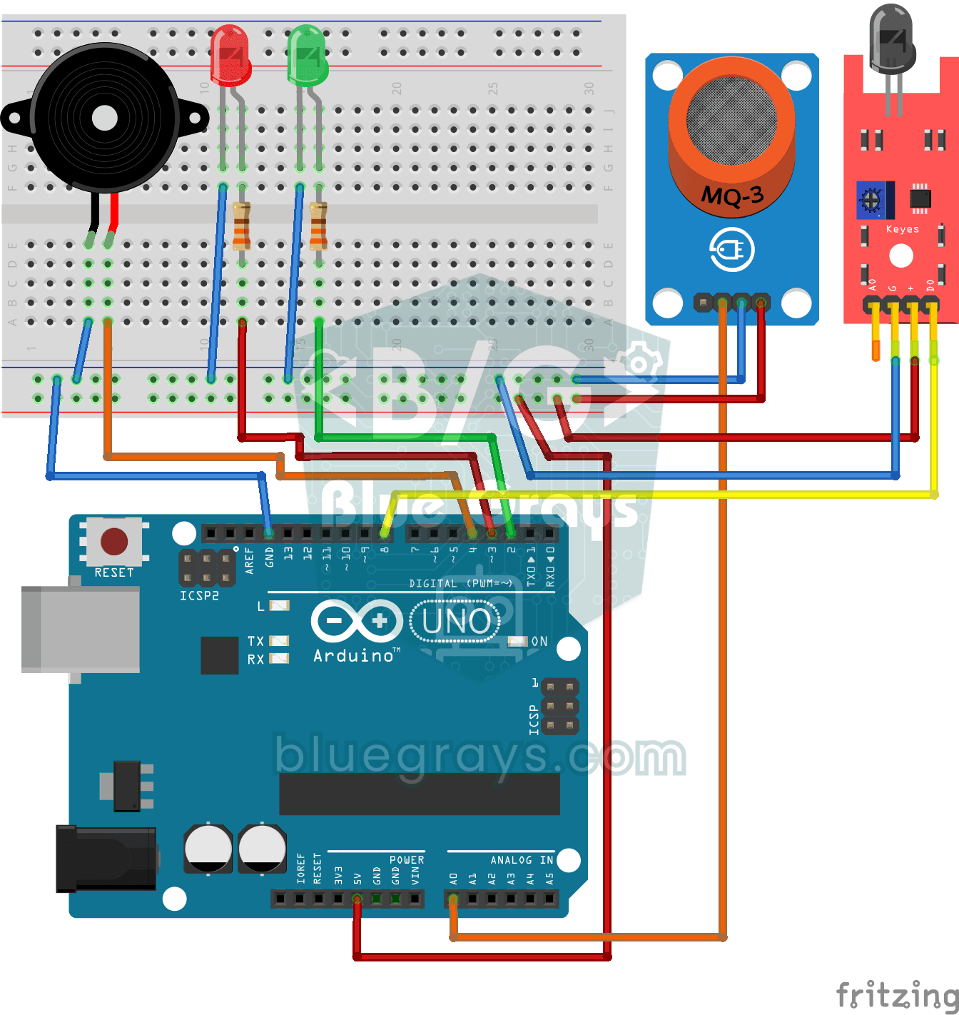
Flame and Gas Sensor Alarm
A little guard that warns you right away when gas leaks or a flame appears somewhere.

ESP32 MQ-2 Gas/Smoke Detector Alarm
In this project, combustible gas (LPG, methane, propane) and smoke detection is performed using an MQ-2 gas sensor module, and a siren-like alarm is played through a passive buzzer upon detection. The sensor's digital threshold output (DO) is connected to GPIO 4 on the ESP32; when gas or smoke exceeds the threshold, DO goes LOW and the alarm is triggered. Sensitivity is adjusted via the module's potentiometer. The passive buzzer is driven using tone() to produce a two-frequency siren effect.
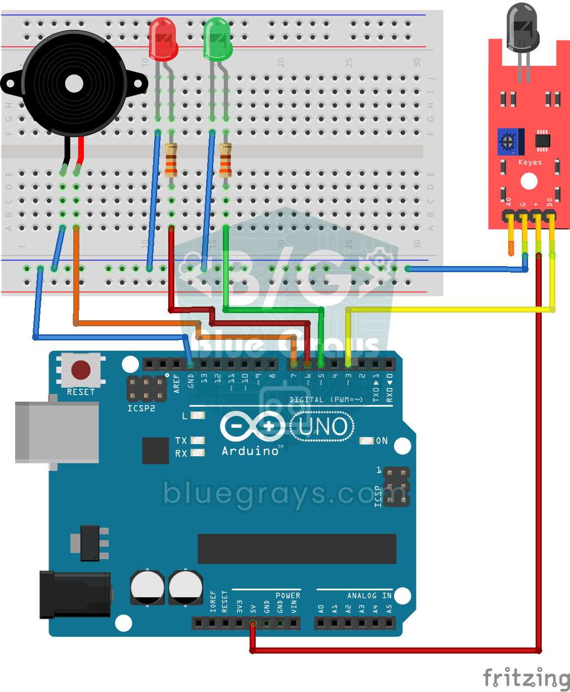
Using a Flame Sensor
A little guard that spots fire before you do, in the kitchen or the workshop. The flame sensor picks up the invisible light that fire gives off; while all is well the green LED is on, and when it…
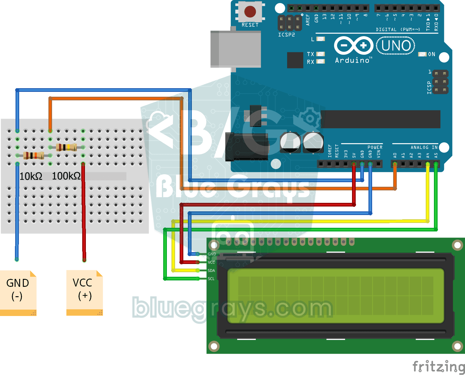
Digital Voltmeter with LCD Display
Find out how much voltage a battery or power adapter gives with a meter you built yourself.
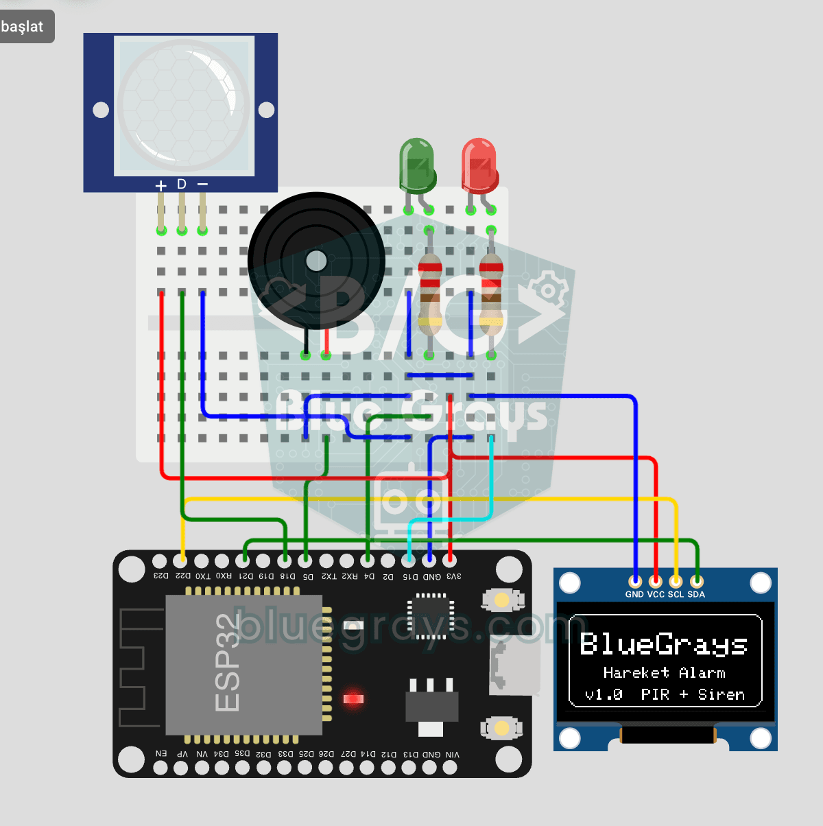
ESP32 Motion Alarm System (PIR + Buzzer + LED + Telegram)
A smart security alarm: when the PIR sensor detects motion, it sounds the buzzer, lights the LED and sends the owner an instant Telegram notification. A 30-second cooldown limits how often the alarm repeats; it does not filter out the PIR sensor's false detections. Use it at home, in a garage, a storeroom or a study.