
MH-Z19 CO2 Sensor: Measure ppm with Arduino, ESP32 and Pico
How do you use the MH-Z19B NDIR CO2 sensor? UART wiring, reading ppm, ABC calibration, warm-up and Uno, ESP32, Pico code for a ventilation alert.

The MH-Z19 CO2 sensor is an NDIR sensor that uses infrared light to measure the amount of carbon dioxide in the air directly in ppm (parts per million). It connects to an Arduino, ESP32 or Raspberry Pi Pico with just four wires (5 V, GND, TX, RX) and returns a real CO2 value over UART within milliseconds. Unlike cheap gas sensors, it doesn't guess; it measures how much light the CO2 molecules in the air absorb. That makes it one of the most reliable and affordable ways to build a ventilation alert for classrooms, bedrooms and offices where the windows stay shut in winter.
In this post you'll learn how the MH-Z19B works, its pins and correct wiring, how to read ppm with UART commands, the 3-minute warm-up and the often confusing automatic calibration (ABC). Then we'll build a ventilation alert with green, yellow and red LEDs, with working code for the Arduino Uno (SoftwareSerial), ESP32 (hardware UART) and Raspberry Pi Pico (MicroPython). Once you see how CO2 in a closed classroom can pass 2000 ppm within a single lesson, you'll understand why this sensor is so popular.
What is the MH-Z19 CO2 sensor and how does it work?
NDIR stands for Non-Dispersive Infrared. A small lamp inside the sensor emits infrared light; the light passes through a measurement chamber filled with air that enters through a filter and reaches the detector on the other side. CO2 molecules strongly absorb light at a wavelength of about 4.26 micrometres. A narrow-band optical filter in front of the detector lets only this wavelength through; the more CO2 in the air, the less light reaches the detector. A microcontroller inside the sensor corrects this difference for temperature, converts it to a ppm value and sends it to you as a ready-made number. Because the measurement relies on physical absorption, it is far more selective than heated semiconductor sensors such as the MQ series: perfume, alcohol or cooking smells don't change the CO2 reading.
| Feature | MH-Z19B value |
|---|---|
| Measurement method | NDIR (non-dispersive infrared absorption) |
| Measurement range | 0–2000 or 0–5000 ppm (selected by command; a 10000 ppm version also exists) |
| Accuracy | About ±(50 ppm + 3–5% of the reading), depending on the version |
| Supply voltage | 4.5–5.5 V DC |
| Current | Under 60 mA on average, about 150 mA peak |
| Interface | UART 9600 baud 8N1, 3.3 V level; also a PWM output |
| Warm-up | 3 minutes |
| Response time (T90) | Under 120 seconds |
| Operating conditions | 0–50 °C, 0–90% relative humidity (non-condensing) |
| Lifespan | More than 5 years (manufacturer's figure) |
CO2 levels: what does each ppm value mean?
In clean outdoor air, CO2 today is around 420 ppm. In a closed room, every person keeps adding CO2 with each breath: a resting adult gives off about 15–20 litres of CO2 per hour. Let's do a quick calculation: in a 150 m³ classroom, 25 students produce about 0.4 m³ of CO2 per hour. With no ventilation at all, that would be 0.4 / 150 ≈ 0.0027, or an increase of about 2700 ppm per hour. Thanks to gaps around doors and leaks the real rise is slower, but seeing 2000 ppm at the end of a lesson with the windows shut is far from rare. At these levels CO2 isn't directly toxic, but it's the best indicator of poor ventilation and is associated with fatigue, headaches and loss of concentration. Many school and office guidelines treat around 1000 ppm as the ventilation limit.
| CO2 range | Assessment | Alert in our code |
|---|---|---|
| 400–800 ppm | Fresh, well-ventilated space | Green LED |
| 800–1200 ppm | Acceptable, the air is starting to go stale | Yellow LED |
| 1200–2000 ppm | Poor, time to open a window | Red LED + buzzer |
| Above 2000 ppm | Very poor; drowsiness and headaches become common | Red LED + buzzer |
| 5000 ppm | 8-hour occupational exposure limit for workplaces | Top of the measurement range |
MH-Z19B pins and wiring diagram
The MH-Z19B usually has 7 pins: Vin (supply), GND, TX and RX (UART), PWM (pulse-width output), HD (manual zero calibration) and, on some versions, Vo (analog voltage output). On the PWM output the period is about 1004 ms and the value is calculated with the formula ppm = range × (TH − 2 ms) / (TH + TL − 4 ms); but since you have to wait a second for every reading, UART is much more practical. We'll use UART, so PWM and HD can stay unconnected. On UART the wires are always crossed: the sensor's TX goes to the board's RX, and the sensor's RX goes to the board's TX. You can find the basics of serial communication in detail in the UART serial communication post.
| MH-Z19B pin | Arduino Uno | ESP32 | Raspberry Pi Pico |
|---|---|---|---|
| Vin (5 V) | 5V | VIN (5V) | VBUS (pin 40) |
| GND | GND | GND | GND |
| TX | D10 (SoftwareSerial RX) | GPIO 16 (UART2 RX) | GP1 (UART0 RX) |
| RX | D11 (via 1 kΩ + 2 kΩ divider) | GPIO 17 (UART2 TX) | GP0 (UART0 TX) |
| PWM | Unconnected | Unconnected | Unconnected |
| HD | Unconnected (to GND during calibration) | Unconnected | Unconnected |
| Alert LEDs / buzzer | D4, D5, D6 / D8 | GPIO 26 / GPIO 27 | GP15 |
The sensor's TX output is at 3.3 V, and the Uno reads it as HIGH without any problem. In the opposite direction, though, the Uno's TX pin outputs 5 V. The manufacturer's documents give the interface level as 3.3 V; although some modules tolerate 5 V, the safest approach is a simple voltage divider between the Uno's D11 pin and the sensor's RX: 1 kΩ from D11 to the sensor's RX, and 2 kΩ from the sensor's RX to GND. The output becomes 5 × 2 / (1 + 2) = 3.33 V. You can check the values against the resistors you have with the voltage divider calculator, or use a bidirectional logic level converter. The ESP32 and Pico already run at 3.3 V, so they don't need a divider.
UART protocol: how do you talk to the sensor?
The MH-Z19B works with 9600 baud, 8 data bits, no parity, 1 stop bit (8N1). Every command and every reply is exactly 9 bytes long. Commands start with 0xFF, the second byte is the sensor number (0x01), the third is the command code, and the last byte is the checksum. The checksum is found from the sum of bytes 1 to 7 like this: checksum = 0xFF − (byte1 + … + byte7) + 1, with the result truncated to a single byte. In the reply to the read command, byte 0 is 0xFF and byte 1 is 0x86; the CO2 value is in bytes 2 and 3: ppm = high byte × 256 + low byte. For example, if the reply begins with FF 86 02 58, the value is 2 × 256 + 88 = 600 ppm. Byte 4 is an undocumented, rough temperature value (value − 40 °C) and is only meant to give an idea; use a separate sensor for real temperature measurement.
| Operation | 9 bytes sent (hex) | Description |
|---|---|---|
| Read CO2 | FF 01 86 00 00 00 00 00 79 | Bytes 2 and 3 of the reply are the ppm value |
| ABC on | FF 01 79 A0 00 00 00 00 E6 | Turns on the 24-hour automatic baseline correction (factory setting) |
| ABC off | FF 01 79 00 00 00 00 00 86 | Turns off automatic calibration for greenhouses and enclosed spaces |
| Zero calibration | FF 01 87 00 00 00 00 00 78 | Treats the current environment as 400 ppm; do this only outdoors |
| Range 2000 ppm | FF 01 99 00 00 00 07 D0 8F | Sets the measurement range to 0–2000 ppm |
| Range 5000 ppm | FF 01 99 00 00 00 13 88 CB | Sets the measurement range to 0–5000 ppm |
Step by step: measuring CO2 with the Arduino Uno
- Connect the sensor's Vin pin to the Uno's 5V pin and its GND pin to GND.
- Connect the sensor's TX pin to D10; this pin will be SoftwareSerial's RX.
- Connect the Uno's D11 pin to the sensor's RX pin through the 1 kΩ + 2 kΩ voltage divider.
- Connect the green, yellow and red LEDs to D4, D5 and D6 through 220 Ω resistors, and the passive buzzer to D8.
- Upload the code, open the Serial Monitor at 9600 baud and wait for the first 3-minute warm-up to finish.
- Hold the sensor in front of an open window for a few minutes and check that it reads around 400–480 ppm, then breathe out from about 30 cm away and watch the value rise quickly.
1#include <SoftwareSerial.h>
2
3// MH-Z19B TX -> D10, MH-Z19B RX -> D11 (1k + 2k bölücü / 1k + 2k divider)
4SoftwareSerial co2Serial(10, 11);   // RX, TX
5
6const byte GREEN_LED  = 4;
7const byte YELLOW_LED = 5;
8const byte RED_LED    = 6;
9const byte BUZZER     = 8;          // pasif buzzer / passive buzzer
10
11const byte CMD_READ[9]   = {0xFF, 0x01, 0x86, 0x00, 0x00, 0x00, 0x00, 0x00, 0x79};
12const byte CMD_ABC_ON[9] = {0xFF, 0x01, 0x79, 0xA0, 0x00, 0x00, 0x00, 0x00, 0xE6};
13
14const unsigned long WARMUP_MS     = 180000UL;  // 3 dakika ön ısınma / 3 minute warm-up
15const unsigned long READ_INTERVAL = 5000UL;    // 5 saniyede bir ölç / read every 5 s
16
17unsigned long lastRead = 0;
18
19byte calcChecksum(const byte *packet) {
20  byte sum = 0;
21  for (byte i = 1; i < 8; i++) {
22    sum += packet[i];
23  }
24  return (byte)(0xFF - sum + 1);
25}
26
27int readCO2() {
28  byte resp[9];
29  while (co2Serial.available()) {
30    co2Serial.read();                                 // eski baytları at / drop old bytes
31  }
32  co2Serial.write(CMD_READ, 9);
33
34  byte count = 0;
35  unsigned long start = millis();
36  while (count < 9 && millis() - start < 300) {
37    if (co2Serial.available()) {
38      resp[count++] = co2Serial.read();
39    }
40  }
41  if (count < 9) return -1;                           // cevap yok / no answer
42  if (resp[0] != 0xFF || resp[1] != 0x86) return -2;  // yanlış başlık / wrong header
43  if (resp[8] != calcChecksum(resp)) return -3;       // checksum hatası / checksum error
44  return ((int)resp[2] << 8) | resp[3];               // ppm = yüksek*256 + düşük / high*256 + low
45}
46
47void setLeds(bool g, bool y, bool r) {
48  digitalWrite(GREEN_LED, g ? HIGH : LOW);
49  digitalWrite(YELLOW_LED, y ? HIGH : LOW);
50  digitalWrite(RED_LED, r ? HIGH : LOW);
51}
52
53void setup() {
54  Serial.begin(9600);
55  co2Serial.begin(9600);
56  pinMode(GREEN_LED, OUTPUT);
57  pinMode(YELLOW_LED, OUTPUT);
58  pinMode(RED_LED, OUTPUT);
59  pinMode(BUZZER, OUTPUT);
60  delay(500);
61  co2Serial.write(CMD_ABC_ON, 9);   // ABC açık; sera için kapat / ABC on; turn off for greenhouses
62  Serial.println(F("MH-Z19B on isinma basladi / warm-up started"));
63}
64
65void loop() {
66  unsigned long now = millis();
67  if (now - lastRead < READ_INTERVAL) return;
68  lastRead = now;
69
70  if (now < WARMUP_MS) {
71    Serial.print(F("Isiniyor / Warming up: "));
72    Serial.print((WARMUP_MS - now) / 1000);
73    Serial.println(F(" s"));
74    return;
75  }
76
77  int ppm = readCO2();
78  if (ppm < 0) {
79    Serial.print(F("Okuma hatasi / Read error: "));
80    Serial.println(ppm);
81    return;
82  }
83
84  Serial.print(F("CO2: "));
85  Serial.print(ppm);
86  Serial.println(F(" ppm"));
87
88  if (ppm < 800) {
89    setLeds(true, false, false);        // temiz hava / fresh air
90  } else if (ppm < 1200) {
91    setLeds(false, true, false);        // havalandırmaya hazırlan / ventilate soon
92  } else {
93    setLeds(false, false, true);        // pencereyi aç / open the window
94    tone(BUZZER, 2000, 200);
95  }
96}
Every 5 seconds the code sends the 9-byte read command to the sensor, then collects the 9-byte reply for up to 300 ms. If the reply's header (FF 86) or checksum doesn't match, the value is discarded, so a noisy line can't trigger a false alarm. The readCO2() function returns a negative code on error: -1 means no reply, -2 means a wrong header, -3 means a bad checksum. Because timing is done with millis() instead of delay(), loop() isn't blocked; when you add a button or a display later, the code stays responsive. You can find the reasoning behind this approach in the millis vs delay post. If you prefer a ready-made library, the MH-Z19 library (by Jonathan Dempsey) in the Library Manager wraps the same protocol with functions like getCO2() and autoCalibration(); but knowing the raw protocol makes it much easier to find the problem when the sensor behaves unexpectedly.
Warm-up: why shouldn't you trust the first 3 minutes?
Measurements aren't reliable until the infrared lamp and detector reach a stable temperature. The manufacturer gives the warm-up time as 3 minutes; during this time the sensor may return constant or meaningless values (for example, always 400 or 500 ppm). That's why our code takes no readings in the first 180 seconds and only prints the remaining time. In addition, the sensor's response time T90 is under 2 minutes: when the environment changes suddenly, it can take a minute or two to reach 90% of the true value, so it's normal for the reading to fall slowly after you open a window. If you see small fluctuations between measurements, averaging the last 5–10 readings steadies the displayed value; see the sensor data filtering post for methods. If you'll use the device for a long time, keeping it powered continuously gives more consistent results than switching it off and on each time.
Automatic calibration (ABC) and manual zero calibration
The zero point of NDIR sensors slowly drifts over months and years. The MH-Z19B corrects this with ABC (Automatic Baseline Correction): in every 24-hour period, the sensor treats the lowest value it saw as fresh air, i.e. about 400 ppm, and adjusts its baseline accordingly. ABC is on from the factory. In classrooms, offices and bedrooms that are properly ventilated at least once a day, this is very useful; you get reasonable accuracy for years without bothering with calibration. However, in greenhouses, enclosed mushroom rooms or any place where CO2 never drops to 400 ppm, ABC is harmful: the sensor mistakes, say, 700 ppm for fresh air and shifts all your measurements down by about 300 ppm. In such places, disable ABC with the ABC-off command and do a manual calibration at regular intervals.
For manual zero calibration, run the sensor outdoors, away from wind and people's breath, and leave it for at least 20 minutes. Then either send the 0x87 zero-calibration command or connect the HD pin to GND for at least 7 seconds. The sensor records the current environment as 400 ppm. Never do this in a closed room; a sensor that takes 900 ppm indoors for 400 will always show you better air than you really have, and the whole point of the alert device is lost. The 0x99 command is also used to choose between the 2000 ppm and 5000 ppm ranges; in crowded classrooms the 5000 ppm range is safer so the value doesn't hit the ceiling at 2000 ppm.
Using the MH-Z19B with the ESP32
The ESP32 has three hardware UARTs and their pins can be assigned to any GPIO you like, so there's no need for SoftwareSerial. Connect the sensor's Vin to the ESP32 dev board's VIN (5V) pin, which provides the 5 V coming from USB. The sensor's TX goes to GPIO 16 and its RX to GPIO 17; since both lines are at 3.3 V level, they connect directly. The code below compiles the same way on ESP32 Arduino core 2.x and 3.x; when the value exceeds 1200 ppm it lights the LED on GPIO 26 and gives a short beep from the active buzzer on GPIO 27. On boards with WROVER modules, GPIO 16 and 17 are reserved for PSRAM; in that case choose, for example, GPIO 32 and 33. Once you connect the board to Wi-Fi, you can show the same value on a web page, on your phone or in Home Assistant.
1#include <Arduino.h>
2
3HardwareSerial co2Serial(2);        // UART2
4
5const int CO2_RX    = 16;   // ESP32 RX <- MH-Z19B TX
6const int CO2_TX    = 17;   // ESP32 TX -> MH-Z19B RX
7const int ALARM_LED = 26;
8const int BUZZER    = 27;   // aktif buzzer / active buzzer
9const int ALARM_PPM = 1200;
10
11const uint8_t CMD_READ[9] = {0xFF, 0x01, 0x86, 0x00, 0x00, 0x00, 0x00, 0x00, 0x79};
12const unsigned long WARMUP_MS = 180000UL;   // 3 dakika ön ısınma / 3 minute warm-up
13
14uint8_t calcChecksum(const uint8_t *packet) {
15  uint8_t sum = 0;
16  for (int i = 1; i < 8; i++) {
17    sum += packet[i];
18  }
19  return (uint8_t)(0xFF - sum + 1);
20}
21
22int readCO2() {
23  uint8_t resp[9];
24  while (co2Serial.available()) {
25    co2Serial.read();                                   // tamponu temizle / flush buffer
26  }
27  co2Serial.write(CMD_READ, sizeof(CMD_READ));
28  if (co2Serial.readBytes(resp, 9) != 9) return -1;     // zaman aşımı / timeout
29  if (resp[0] != 0xFF || resp[1] != 0x86) return -2;    // yanlış başlık / wrong header
30  if (resp[8] != calcChecksum(resp)) return -3;         // checksum hatası / checksum error
31  return resp[2] * 256 + resp[3];
32}
33
34void setup() {
35  Serial.begin(115200);
36  co2Serial.begin(9600, SERIAL_8N1, CO2_RX, CO2_TX);
37  co2Serial.setTimeout(300);           // readBytes en fazla 300 ms bekler / readBytes waits max 300 ms
38  pinMode(ALARM_LED, OUTPUT);
39  pinMode(BUZZER, OUTPUT);
40  Serial.println("MH-Z19B + ESP32 hazir / ready");
41}
42
43void loop() {
44  static unsigned long lastRead = 0;
45  unsigned long now = millis();
46  if (now - lastRead < 5000) return;
47  lastRead = now;
48
49  if (now < WARMUP_MS) {
50    Serial.printf("Isiniyor / Warming up: %lu s\n", (WARMUP_MS - now) / 1000);
51    return;
52  }
53
54  int ppm = readCO2();
55  if (ppm < 0) {
56    Serial.printf("Okuma hatasi / Read error: %d\n", ppm);
57    return;
58  }
59  Serial.printf("CO2: %d ppm\n", ppm);
60
61  bool alarm = (ppm >= ALARM_PPM);
62  digitalWrite(ALARM_LED, alarm ? HIGH : LOW);
63  if (alarm) {
64    digitalWrite(BUZZER, HIGH);        // kısa bip / short beep
65    delay(150);
66    digitalWrite(BUZZER, LOW);
67  }
68}
CO2 measurement with the Raspberry Pi Pico and MicroPython
On the Pico, UART0 is by default on pins GP0 (TX) and GP1 (RX). Connect the sensor's Vin to the Pico's VBUS pin (pin 40, the 5 V from USB); the 3V3 output isn't enough for the sensor. If you power the Pico from a battery instead of USB, there's no voltage on VBUS and you need to give the sensor a separate 5 V source. The sensor's TX goes to GP1 and its RX to GP0. The code sends the same 9-byte command as the Arduino version, checks the checksum with Python's sum() function, and lights the LED on GP15 (with a 220 Ω resistor) above 1200 ppm. If you're new to MicroPython, you can first take a look at the MicroPython basics post.
1from machine import UART, Pin
2import time
3
4# MH-Z19B TX -> GP1, MH-Z19B RX -> GP0, Vin -> VBUS (5 V)
5uart = UART(0, baudrate=9600, tx=Pin(0), rx=Pin(1), timeout=300)
6led = Pin(15, Pin.OUT)                      # uyarı LED'i / warning LED
7
8CMD_READ = bytes([0xFF, 0x01, 0x86, 0x00, 0x00, 0x00, 0x00, 0x00, 0x79])
9WARMUP_MS = 180000                          # 3 dakika ön ısınma / 3 minute warm-up
10ALARM_PPM = 1200
11start = time.ticks_ms()
12
13def checksum(packet):
14    return (0xFF - (sum(packet[1:8]) & 0xFF) + 1) & 0xFF
15
16def read_co2():
17    while uart.any():
18        uart.read()                         # eski baytları at / drop old bytes
19    uart.write(CMD_READ)
20    time.sleep_ms(100)                      # cevabın gelmesini bekle / wait for the answer
21    resp = uart.read(9)
22    if not resp or len(resp) != 9:
23        return None                         # cevap yok / no answer
24    if resp[0] != 0xFF or resp[1] != 0x86:
25        return None                         # yanlış başlık / wrong header
26    if resp[8] != checksum(resp):
27        return None                         # checksum hatası / checksum error
28    return resp[2] * 256 + resp[3]
29
30while True:
31    elapsed = time.ticks_diff(time.ticks_ms(), start)
32    if elapsed < WARMUP_MS:
33        print("Isiniyor / Warming up:", (WARMUP_MS - elapsed) // 1000, "s")
34    else:
35        ppm = read_co2()
36        if ppm is None:
37            print("Okuma hatasi / Read error")
38        else:
39            print("CO2:", ppm, "ppm")
40            led.value(1 if ppm >= ALARM_PPM else 0)
41    time.sleep(5)
Where should you place the sensor in a classroom or room?
The right location matters more than the right code. Place the sensor at the height where people breathe while seated, about 1–1.5 metres above the floor, on a wall that represents the average of the room. If you put it in a window or doorway, the value will read lower than reality because of the fresh air coming in; if you put it on a desk very close to someone's face, you'll see spikes with every breath. Also avoid places like the top of a radiator, a window in direct sunlight and a bathroom where humidity condenses; the sensor is designed for 0–50 °C and non-condensing humidity. Air enters through the sensor's filtered surfaces; if you put it in an enclosure, make plenty of holes and don't block airflow around the sensor. If your Uno or ESP32 resets because of the lamp's momentary current draw, adding a 100 µF electrolytic and a 100 nF ceramic capacitor between the sensor's Vin and GND steadies the supply.
Project ideas with the MH-Z19
- Classroom ventilation traffic light: Put the green, yellow and red LED circuit from this post in a box and hang it where it can be seen from the teacher's desk.
- Desk display with a screen: Show the CO2 value in big digits on an SSD1306 OLED display or an I2C LCD.
- Phone notification: With the ESP32, send a message through a Telegram bot when the value goes above 1200 ppm.
- Smart home panel: Send the readings to Home Assistant with MQTT and Home Assistant, plot a daily graph and set up automations.
- Automatic ventilation fan: Run an extractor fan when CO2 rises; see the Arduino fan control post for fan-driving details.
- Greenhouse monitoring: Turn ABC off and add CO2 measurement to the smart greenhouse project, and watch on the graph how plants use up CO2 during the day.
- Colour air indicator: Smoothly fade a single WS2812B LED from green at 400 ppm to red at 2000 ppm.
- Data logger: Write a day's measurements to an SD card and see in which lesson the air gets worst; you'll get a strong dataset for science fairs and school research projects.
Common mistakes and how to fix them
| Symptom | Likely cause | Fix |
|---|---|---|
| Constant -1 (no answer) | TX and RX wired straight through, or the sensor is powered from 3.3 V | Cross TX to RX and give Vin 5 V |
| Frequent -3 (checksum error) | Loose breadboard wire, long cable, or a pin unsuitable for SoftwareSerial | Shorten the wires; on the Mega and Leonardo use pins supported for RX, on the Uno D10 is safe |
| Constant 400 or 500 ppm in the first minutes | Warm-up is still in progress | Wait at least 3 minutes, then measure |
| Values keep reading low as days pass | ABC picked the wrong baseline in a space that is never ventilated | Turn ABC off and do a manual calibration outdoors |
| Value gets stuck at 2000 ppm | Measurement range is set to 2000 ppm | Set the range to 5000 ppm with the 0x99 command |
| Board resets or values jump | The lamp's roughly 150 mA momentary current collapses a weak supply | Add a 100 µF capacitor between Vin and GND and use a solid 5 V source |
| Values too low after calibration | Zero calibration was done in a closed room | Repeat the calibration outdoors after waiting 20 minutes |
The MH-Z19B is one of the sensors with the best balance of price and accuracy among those that really measure CO2; once it is powered properly, warmed up for 3 minutes and the ABC setting is chosen to suit the environment, it works reliably for years. For general air quality and odours you can also look at the MQ-135 post, and for volatile organic compounds the CCS811 post. In the BlueGrays app you'll find temperature and humidity measurement, gas alarm, and LCD and OLED ESP32 projects with step-by-step circuit diagrams and code, and you can combine them with this sensor to build your own air quality station.
Frequently asked questions
How many ppm of CO2 should a room have?
Outdoors, CO2 is about 420 ppm, and a well-ventilated room stays below 800 ppm. Around 1000–1200 ppm is a sign that the air has gone stale and it's time to open a window. Above 2000 ppm, headaches, drowsiness and loss of concentration become common.
What is the difference between the MH-Z19B and the MH-Z19C?
Both are NDIR sensors with the same pinout and the same UART commands, so the code in this post works on both. The C version is the newer, more economical successor to the B. Because the C version is more sensitive to supply voltage, it's important to give it a stable, true 5 V.
Does the MH-Z19 sensor work at 3.3 V?
No. The sensor's supply must be in the 4.5–5.5 V range; at 3.3 V the infrared lamp doesn't work properly and the sensor doesn't respond. However, the UART lines are at 3.3 V level, so you can power the sensor from 5 V and connect TX and RX directly to an ESP32 or Pico.
Should I turn off the MH-Z19's automatic calibration (ABC)?
In classrooms, offices and homes that are properly ventilated at least once a day, ABC should stay on; the sensor corrects itself every 24 hours against fresh air. In greenhouses, closed storage rooms or anywhere CO2 never drops to 400 ppm, ABC wrongly shifts the values downward. There, turn ABC off and do a manual calibration outdoors from time to time.
What is the difference between the MH-Z19 and the MQ-135?
The MQ-135 is a heated semiconductor gas sensor; it reacts to alcohol, ammonia, smoke and many other gases together, and can only give a rough estimate of CO2. The MH-Z19 measures CO2 directly by infrared absorption, is almost unaffected by other gases and gives a calibrated value in ppm. For a ventilation alert, the MH-Z19 is the right choice.
Why does the MH-Z19 show wrong values when first powered on?
The sensor's infrared lamp and detector need about 3 minutes of warm-up to reach a stable temperature. During this time it may return constant or meaningless values. In your code, ignore the readings from the first 3 minutes, and wait another 1–2 minutes for the value to settle after the environment changes suddenly.
Projects to build after reading this
See all projects
Temperature and Humidity with DHT11
How warm is your room, and is the air humid or dry? The DHT11 sensor measures temperature and humidity, and the Arduino writes the values on a two-line LCD screen, refreshing every couple of seconds.
Using a Buzzer
Ever wondered how a doorbell or an alarm makes its sound? The Arduino makes a small buzzer beep at short intervals: beep, pause, beep, pause.

ESP32 MQ-2 Gas/Smoke Detector Alarm
In this project, combustible gas (LPG, methane, propane) and smoke detection is performed using an MQ-2 gas sensor module, and a siren-like alarm is played through a passive buzzer upon detection. The sensor's digital threshold output (DO) is connected to GPIO 4 on the ESP32; when gas or smoke exceeds the threshold, DO goes LOW and the alarm is triggered. Sensitivity is adjusted via the module's potentiometer. The passive buzzer is driven using tone() to produce a two-frequency siren effect.
Using a Gas Sensor
A little guard that notices a gas leak in the kitchen before you do. The gas sensor keeps sniffing the air; while everything is fine the green LED stays on, and when the gas in the air passes a…
Flame and Gas Sensor Alarm
A little guard that warns you right away when gas leaks or a flame appears somewhere.

ESP32 DHT22 Temperature and Humidity (with LCD Display)
This project measures ambient temperature and humidity using a DHT22 sensor and displays the data in real time on a 16x2 I2C LCD. Data is read from the sensor using the one-wire protocol via the Adafruit DHT library. This project serves as the foundation for IoT weather stations, smart home automation, or environmental monitoring systems in greenhouses. Communication with the DHT22 is established via the ESP32's GPIO 4 pin.

ESP32 HTTPClient + Weather API (with SSD1306 OLED Display)
In this project the ESP32 makes a REST API call over the internet to a weather API (wttr.in) using HTTPClient.h. Unlike the I2C LCD version, it uses an SSD1306 OLED (128×64) display, with large text and vector icons for a richer look. Seven weather icons (sunny, rainy, snowy and more) are drawn on the fly, with no bitmap files.
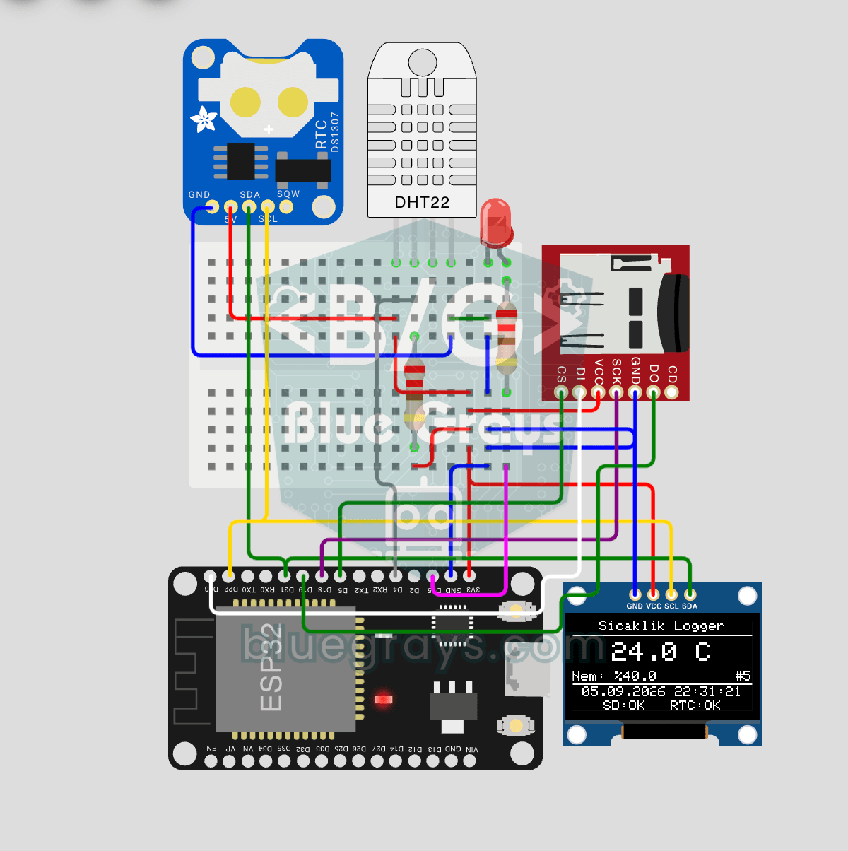
ESP32 Temperature Data Logger (DHT22 + DS1307 RTC + microSD + OLED)
Build a timed temperature and humidity logger with the ESP32! A DHT22 sensor reads temperature and humidity once a minute, and each reading is saved to a microSD card in CSV format with a real-time stamp from the DS1307 RTC module. The OLED display shows the latest temperature, humidity, timestamp and total number of records live, in large text.