
Raspberry Pi Pico W Phone Control: LED, Relay and DHT22 Sensor
Control a Raspberry Pi Pico W from your phone: set up arduino-pico in Arduino IDE, wire an LED and relay to GP15, a DHT22 to GP16, and see live graphs in BlueGrays IoT.

Controlling a Raspberry Pi Pico W from your phone means switching on the living room lamp from bed, checking the room temperature while you're at work, or seeing remotely whether you left the door open. The wireless chip on the Pico W connects the board to a 2.4 GHz Wi-Fi network. With BlueGrays IoT, the board connects to the BlueGrays server over an encrypted WebSocket connection (TLS, port 443), and your phone connects to the same server. That means your phone and the board don't have to be on the same network: you can flip switches from outside the house over mobile data. No port forwarding, no static IP address and no server of your own required.
In this guide you'll set up a Pico W from scratch. First you'll install the right board package in Arduino IDE and see how to use the BOOTSEL button for the first upload. Then you'll create a device in the app in 5 steps, test it with an LED on GP15, and swap in a relay module on the same pin. After that you'll connect a DHT22 to GP16 and watch temperature and humidity on your phone as live values and graphs. At the end you'll find the Pico W pins for all 8 ready-made templates, fixes for Pico W-specific problems and a quick comparison with the ESP32.
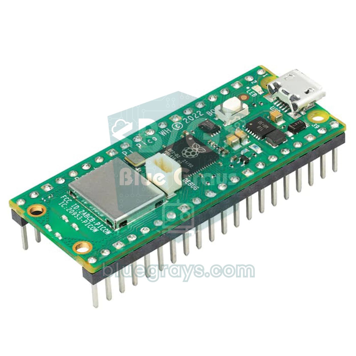
Pico vs Pico W: only the W has Wi-Fi
There are four boards in the Raspberry Pi Pico family, and at first glance they look almost identical. The difference comes down to the letter W in the name: W stands for wireless. The Pico W and Pico 2 W have a small metal-shielded wireless chip (Infineon CYW43439) next to the USB port and a PCB antenna at the end of the board. The plain Pico and Pico 2 don't have this chip. No matter how powerful they are, these boards can't join Wi-Fi, so they can't be controlled from your phone. For the board's general specs, see What Is the Raspberry Pi Pico?
| Board | Processor | Wi-Fi | Phone control (BlueGrays IoT) |
|---|---|---|---|
| Raspberry Pi Pico | RP2040, dual-core, 133 MHz | None | No |
| Raspberry Pi Pico W | RP2040, dual-core, 133 MHz | 2.4 GHz (CYW43439) | Yes |
| Raspberry Pi Pico 2 | RP2350, dual-core, 150 MHz | None | No |
| Raspberry Pi Pico 2 W | RP2350, dual-core, 150 MHz | 2.4 GHz (CYW43439) | Yes |
When people think of the Pico, MicroPython and Thonny usually come to mind. On this route, though, you'll use Arduino IDE. Here's why: BlueGraysIoT, which handles the connection between your phone and the board, is an Arduino library written in C++. Ohmi in the app generates the code as an Arduino sketch tailored to your board, Wi-Fi details and device key. Because the same library also runs on the ESP32, the templates work the same way on both boards. Your MicroPython knowledge isn't wasted: if you want a simple local control panel on the same network, the method in Pico W Wi-Fi Web Server still works. But access from outside the house, graph history and a ready-made phone interface come from this Arduino IDE route.
What you need
| Part or tool | What for? | Note |
|---|---|---|
| Raspberry Pi Pico W (or Pico 2 W) | Main board | Get one with soldered headers; if you don't want to solder, buy the WH version with pre-soldered headers |
| Micro USB data cable | Uploading code and power | Charge-only cables have no data lines; your computer won't see the board |
| Computer and Arduino IDE | Uploading code to the board | Windows, macOS or Linux |
| Phone and the BlueGrays app | Controlling the board | iOS or Android |
| 2.4 GHz Wi-Fi network | Internet access for the board | It won't connect to 5 GHz networks |
| LED and 220 Ω resistor | First safe test | Always try this before the relay |
| 5 V relay module | Switching a lamp or outlet | Prefer a module with an optocoupler |
| DHT22 temperature and humidity sensor | Live values and graphs | The module version has the pull-up resistor built in |
| Breadboard and jumper wires | Building the circuit | Male-to-female wires are handy for the relay module |
Preparing the Pico W in Arduino IDE
Out of the box, Arduino IDE doesn't recognize the Pico W. First you need to add the arduino-pico core by Earle Philhower. This core supports the Pico W's wireless chip, the Pico 2 W and the networking libraries BlueGraysIoT needs. If you haven't installed the IDE yet, the details are in How to Install Arduino IDE. Then follow these steps in order:
- In Arduino IDE, open File › Preferences and add the arduino-pico package URL to the Additional boards manager URLs field. You'll find the URL on the arduino-pico project page. If the field already contains other URLs, put the new one on a separate line.
- Open Tools › Board › Boards Manager, type pico in the search box and install the Raspberry Pi Pico/RP2040/RP2350 package. The author should be Earle F. Philhower, III. The download can be a few hundred MB.
- Select Raspberry Pi Pico W from the Tools › Board menu. If you're using a Pico 2 W, pick Pico 2 W from the same list. If you select the plain Pico, the Wi-Fi code won't compile.
- In Tools › Manage Libraries, search for BlueGraysIoT and click Install. If it asks about dependencies, choose Install all; WebSockets, ArduinoJson and DHT sensor library come along with it. If you run into trouble, see the How to Add an Arduino Library guide.
- For the first upload, hold down the white BOOTSEL button on the board while plugging in the USB cable, then release it. A drive called RPI-RP2 appears on your computer (on the Pico 2 W it's called RP2350). In the Tools › Port menu, pick the UF2 Board option or similar and click Upload.
- When the first upload finishes, the board restarts and from then on shows up as a normal serial port: something like COM3 on Windows, or /dev/ttyACM0 on macOS and Linux. You usually won't need BOOTSEL for later uploads.
Creating a device in the app in 5 steps
In the BlueGrays app, go to Workshop › My devices › Add new device. The top of the screen shows "Step n / 5". The flow is the same as for the ESP32; on the Pico W, only the board selection, pin names and upload details differ.
- Board and template: For "Which board do you have?", choose Pico W (choose this for the Pico 2 W too). Under "What will it do?", pick one of the 8 templates, for example Room station, and give the device a name like "Living room".
- Parts and circuit: The "Get your parts ready" list and the "Connect the wires" diagram come with Pico W pins: relay on GP15, DHT22 on GP16. Relay templates show the warning "If you'll be working with 220 V, do it with someone who knows how. Try it with an LED first."
- Wi-Fi and code: Enter the name and password of your 2.4 GHz network. If you like, change the pins in the "Connection pins" section, then tap "Create device and prepare code". The code is generated with your device key, which starts with bgd_. Your Wi-Fi password stays on your phone only and is never sent to the server. Use "Copy code" or "Share" to get the code onto your computer.
- Upload in Arduino IDE: Open a new sketch, paste the code and click Upload. Make sure Raspberry Pi Pico W is selected as the board. If needed, hold BOOTSEL while plugging in USB for the first upload. Then open the Serial Monitor at 115200 baud.
- Connection: The "Waiting for your board" screen switches automatically to "Connected: Values now arrive in real time." once the board connects. If it doesn't connect within 2 minutes, check that your network is 2.4 GHz, look for the "Wi-Fi connected" message in the Serial Monitor, and double-check upper and lower case in the password.
Test with an LED first: LED on GP15 with 220 Ω
Before moving to the relay, connect an LED to the same pin to test the code, Wi-Fi and phone connection on a zero-risk circuit. Choose the Relay lamp or Room station template, connect the LED's long leg to GP15 through a 220 Ω resistor and the short leg to GND. With a red LED the current is about (3.3 − 2.0) / 220 ≈ 5.9 mA; that lights the LED clearly without straining the pin. For other colors or currents you can use the LED resistor calculator. You only need to change one line in the code: set RELAY_ACTIVE_LOW = true to false. Most relay modules switch on with a LOW signal, so the code ships with inverted logic by default. If you don't fix this for the LED, it will be on when the switch on your phone is off and go out when you turn it on.
| LED circuit | Pico W pin | Physical pin | Note |
|---|---|---|---|
| 220 Ω resistor → LED long leg (+) | GP15 | 20 | Works whichever side of the LED the resistor is on |
| LED short leg (−) | GND | 18 or 23 | The board has 8 separate GND pins |
Next the relay: a lamp switch with the Pico W
If the LED turns on and off from your phone without trouble, you can move GP15 over to the relay module's IN pin. Set RELAY_ACTIVE_LOW back to true and upload the code again. The relay coil needs 5 V, so power the module not from the 3.3 V pin but from VBUS, which provides 5 V while the board is powered over USB. We covered how relay modules work in detail in What Is a Relay Module?
| Relay module pin | Pico W pin | Physical pin | Note |
|---|---|---|---|
| VCC | VBUS | 40 | About 5 V while the board is powered over USB |
| GND | GND | 38 | Common ground is a must |
| IN | GP15 | 20 | RELAY_PIN = 15 in the code |
| COM and NO | Not connected to the board | - | Wired in series with the load you're switching; on the NO terminal, the circuit closes when the relay energizes |
The Pico W's pins output 3.3 V; most 5 V relay modules trigger fine with that signal, but not all of them. On an active-LOW module, when the pin is HIGH there's still 3.3 V on IN, leaving a 1.7 V difference to the 5 V VCC, and on some modules that's enough to dimly light the input LED; the result is a relay that never releases or behaves erratically. Modules with an optocoupler and a JD-VCC jumper are more reliable here; you can read how they work in What Is an Optocoupler? If the relay doesn't click on, or never releases, first measure the voltage on IN, then try a module designed for 3.3 V triggering.
Temperature and humidity with a DHT22: room station code
Now let's add a sensor and complete the Room station template: the same board will control the lamp and also send temperature and humidity to your phone. The DHT22 (AM2302) measures from −40 to 80 °C with about ±0.5 °C accuracy, and humidity across 0–100% with ±2–5% accuracy, and it runs on 3.3 V. That's why powering it from the 3V3(OUT) pin is the safest option; the data line then reaches the Pico W at 3.3 V logic level. We compared it with its sibling, the DHT11, in DHT11 Temperature and Humidity Sensor.
| DHT22 pin | Pico W pin | Physical pin | Note |
|---|---|---|---|
| VCC (+) | 3V3(OUT) | 36 | 3.3 V output; don't apply 5 V |
| DATA (OUT) | GP16 | 21 | DHT dht(16, DHT22) in the code |
| GND (−) | GND | 23 | Common ground |
| Pull-up resistor | Between DATA and 3V3(OUT) | - | Only the bare 4-pin sensor needs a 10 kΩ; modules have it on board |
The code below is exactly what the app generates for the Pico W with the Room station template. The app fills in the three lines at the top with your device key and Wi-Fi details. You don't need to replace the placeholders you see here yourself; just copy the code from the app.
1/*
2 * Oda istasyonu · BlueGrays IoT
3 * BlueGrays · bluegrays.com
4 * Bu kodu paylaşma: içinde cihaz anahtarın ve Wi-Fi şifren var.
5 * Do not share this code: it contains your device key and Wi-Fi password.
6 */
7
8#include <BlueGraysIoT.h>
9#include <DHT.h>
10
11const char *DEVICE_KEY = "bgd_UYGULAMADAKI_ANAHTARIN";
12const char *WIFI_NAME = "EV_AGI_2_4_GHZ";
13const char *WIFI_PASSWORD = "WIFI_SIFREN";
14
15BlueGraysIoT bg(DEVICE_KEY);
16
17const int RELAY_PIN = 15;           // röle IN ucu GP15 / relay IN on GP15
18const bool RELAY_ACTIVE_LOW = true;  // çoğu röle modülü LOW ile çeker / most relay modules switch on LOW
19void setRelay(bool on) { digitalWrite(RELAY_PIN, (on != RELAY_ACTIVE_LOW) ? HIGH : LOW); }
20DHT dht(16, DHT22);                  // DHT22 veri ucu GP16 / DHT22 data on GP16
21unsigned long lastReadMs = 0;
22
23void setup() {
24  Serial.begin(115200);
25  pinMode(RELAY_PIN, OUTPUT);
26  setRelay(false);
27  bg.onSwitch("lamba", setRelay);
28  dht.begin();
29  bg.setDeadband("sicaklik", 0.1);   // 0,1 °C değişmeden gönderme / send only after a 0.1 °C change
30  bg.setDeadband("nem", 1.0);        // %1 değişmeden gönderme / send only after a 1 % change
31  bg.setDebug(Serial);
32  bg.setLanguage(BG_LANG_TR);
33  bg.begin(WIFI_NAME, WIFI_PASSWORD);
34}
35
36void loop() {
37  bg.loop();  // burada uzun delay() kullanma / avoid long delay() calls here
38  if (millis() - lastReadMs >= 2000) {  // DHT22 en fazla 2 saniyede bir okunur / DHT22 reads at most every 2 s
39    lastReadMs = millis();
40    bg.send("sicaklik", dht.readTemperature());
41    bg.send("nem", dht.readHumidity());
42  }
43}
44| Line | What it does |
|---|---|
| BlueGraysIoT bg(DEVICE_KEY) | Creates the connection object with your device key; the key is only sent in the connection header and is never printed to the Serial Monitor |
| RELAY_PIN = 15 | The relay module's IN pin is on GP15 |
| RELAY_ACTIVE_LOW = true | The relay switches on with LOW; set it to false when testing with an LED |
| setRelay(bool on) | Writes the correct level to the pin depending on whether the relay is active LOW or HIGH |
| DHT dht(16, DHT22) | Sensor data pin is GP16, sensor type is DHT22 |
| bg.onSwitch("lamba", setRelay) | Runs setRelay when you tap the lamba (lamp) switch on your phone |
| bg.setDeadband("sicaklik", 0.1) | No new value is sent until the temperature changes by at least 0.1 °C |
| bg.setDeadband("nem", 1.0) | No new value is sent until the humidity changes by at least 1% |
| bg.setDebug(Serial) and bg.setLanguage(BG_LANG_TR) | Prints status messages to the Serial Monitor in Turkish |
| bg.begin(WIFI_NAME, WIFI_PASSWORD) | Starts connecting to Wi-Fi and the BlueGrays server |
| bg.loop() | Handles incoming commands and keeps the connection alive; must be called frequently inside loop |
| millis() - lastReadMs >= 2000 | Reads the DHT22 every 2 seconds and sends the sicaklik (temperature) and nem (humidity) values with bg.send |
There's a reason behind the timing in the code. The DHT22 can't be read more than once per second; a 2-second interval stays safely within that limit. The reading uses millis() instead of delay(2000) because bg.loop() has to keep running during the wait. Otherwise, when you tapped the switch on your phone, the lamp would respond with a 2-second delay; details in Arduino millis() vs delay(). The library only sends a value when it changes, and without exceeding your plan's rate. So when the room temperature is steady, no data is sent to the server for nothing. If Wi-Fi drops, the library retries at increasing intervals, sends the values it measured while offline once it reconnects, and restores the lamp switch's last state after a power cut. Once the upload finishes, you should first see "Wi-Fi connected" in the Serial Monitor, followed a few seconds later by "BlueGrays IoT: connected".
Pico W pinout table: default pins for all 8 templates
All 8 templates in the app can be built on the Pico W. The table below shows each one's default Pico W pin and the physical pin number on the board. You can change pins in step 3 of the setup. To see where the pins are on your board, check the Pinout tool.
| Template | Parts | Pico W pin | Physical pin | Note |
|---|---|---|---|---|
| Relay lamp | Relay module | GP15 | 20 | Relay VCC → VBUS |
| Temperature and humidity | DHT22 | GP16 | 21 | Powered from 3V3(OUT) |
| Room station | Relay + DHT22 | GP15 + GP16 | 20 + 21 | The code in this post |
| RGB LED strip | WS2812B (30 LEDs in the code) | GP2 | 4 | Adafruit NeoPixel library; power the strip from a separate 5 V supply |
| Door / window | Magnetic reed sensor | GP14 | 19 | INPUT_PULLUP, other lead to GND |
| Soil moisture + pump | Soil sensor + relay + pump | GP26 (ADC0) + GP15 | 31 + 20 | Calibration: dry 3000, wet 1200 |
| Motion detector | PIR (HC-SR501) | GP13 | 17 | PIR output is 3.3 V |
| Servo curtain | SG90 servo | GP17 | 22 | Servo.h bundled with the core; power the servo from a separate 5 V supply |
What will you see on your phone?
Once the board connects, the device screen shows Online and the "Last data … ago" line updates. For the room station you'll see a lamp switch plus live values for temperature (°C) and humidity (%). Tap a value to open its graph: you can switch between 1 h, 24 h, 7 days and 30 days. The 7- and 30-day views show hourly averages, and Lowest, Highest and Latest values appear below the graph. As long as the board stays connected, a new point is added to the graph every minute. If you need to see the code again later, the Code and key section on the device screen shows the full code, your device key and Wi-Fi details. If someone has seen your key, Regenerate key instantly invalidates the old one, and you upload the new code to the board once.
| Feature | Free | Premium |
|---|---|---|
| Number of devices | 1 device (your first device is free) | 10 devices |
| Variables with graph history | 1 | 20 |
| History length | 24 hours | 30 days |
| Minimum interval between sends for the same variable | At least 1 second | At least 0.2 seconds |
The room station has two measured variables: temperature and humidity. On the free plan, graph history is kept for only one of them; you still see live values for both. Limits are enforced on the server, so changing the interval in the code won't get around them. The 2-second reading already stays within the 1-second limit. If you remove a device, the device and its graph history are deleted and your device slot is freed up; that way you can try different templates one after another on the free plan.
Pico W-specific problems and fixes
| Symptom | Likely cause | Fix |
|---|---|---|
| Compilation fails on WiFi.h or network functions | Arduino Mbed OS RP2040 Boards package or plain Pico selected | Select Raspberry Pi Pico W from the Raspberry Pi Pico/RP2040/RP2350 package |
| Tools › Port menu is empty | Charge-only cable, board never programmed, or a crashed sketch | Use a data cable; hold BOOTSEL while plugging in USB and upload again |
| RPI-RP2 drive doesn't appear | BOOTSEL pressed after plugging in the cable, or a faulty cable | Unplug the cable, plug it in while holding BOOTSEL, then release; try another USB port |
| On Linux the port is there but upload gives a permission error | Your user has no serial port permission | Add your user to the dialout group or install the arduino-pico udev rule, then log out and back in |
| "Wi-Fi connected" never appears in the Serial Monitor | 5 GHz network, wrong password or weak signal | Pick the 2.4 GHz network, check upper and lower case in the password, move the board closer to the router |
| Phone sees the network but the Pico W can't connect | Router is on 2.4 GHz channel 12 or 13 | Set the channel to 1–11 in the router settings (1, 6 or 11 are good choices) |
| 2.4 and 5 GHz combined under one network name (band steering) | Board sees the network name but the connection is unstable | Create a separate network name for 2.4 GHz on the router |
| Wi-Fi connected but "BlueGrays IoT: connected" never appears | Old device key, or port 443 blocked on the network | Copy the code again from the Code and key section in the app; try your phone's hotspot |
| Board restarts when the relay switches on | Weak USB power; the relay coil pulls the voltage down | Use a better cable and adapter, or power the relay from a separate 5 V supply with common GND |
| No temperature or humidity readings | DATA wired to the wrong pin, or no pull-up resistor | Connect DATA to GP16 (physical pin 21); add a 10 kΩ pull-up on a bare sensor |
ESP32 or Pico W?
| Feature | ESP32 (Dev Module) | Raspberry Pi Pico W |
|---|---|---|
| Processor | Dual-core, 240 MHz | RP2040, dual-core, 133 MHz (RP2350, 150 MHz on the Pico 2 W) |
| Wireless | 2.4 GHz Wi-Fi + Bluetooth | 2.4 GHz Wi-Fi + Bluetooth |
| Analog input | 12-bit; only ADC1 (GPIO32–39) while Wi-Fi is on | 12-bit; 3 external channels (GP26–28), unaffected by Wi-Fi |
| Usable GPIO | Roughly 25–34 depending on the board | 26 |
| USB | CP210x or CH340 chip, may need a driver | Built into the chip, no driver needed |
| When uploads get stuck | BOOT button | BOOTSEL button |
| Budget | Beginner-friendly | Beginner-friendly |
| Phone control with BlueGrays IoT | Yes, all 8 templates | Yes, all 8 templates |
In short, either one works for this. Start with whichever you have. The Pico W's advantages are its driver-free USB, its tidy pin layout and an ADC that keeps working with Wi-Fi on. The ESP32's advantages are more pins, higher speed and a far larger archive of examples online. If you want to follow the same steps with an ESP32, we covered it using the GPIO26 and GPIO4 pins in How to Control an ESP32 from Your Phone.
IoT template projects built with the Pico W
BlueGrays has 8 IoT template projects, all free: each comes with a full circuit diagram, parts list and code. These three are shown on the Pico W:
- Pico W IoT Temperature and Humidity (DHT22): monitor temperature and humidity from the DHT22 on GP16 as live values and graphs on your phone.
- Pico W IoT Door Sensor (Reed Switch): see the door's Open / Closed state remotely with the magnetic reed sensor on GP14; how the sensor works is explained in Reed Switch.
- Pico W IoT Motion Counter (PIR): track motion / no motion and a counter with the HC-SR501 on GP13, and reset the counter from your phone with the Reset counter button; details in PIR Motion Sensor.
- The other five templates are shown on the ESP32 but also work on the Pico W. When you select Pico W as the board in the app, the pins are filled in automatically according to the table above: Room Station, Lamp Switch, Plant Watering, RGB LED Strip and Curtain Opener.
Once your Pico W is set up in Arduino IDE, moving on to a new phone-controlled project takes just a few minutes: pick a template, build the circuit, upload the code Ohmi prepares. Since your first device is free, you can start with an LED and work your way up to a relay and sensor step by step. In the BlueGrays app, turn on the IoT projects filter in Explore to browse these templates and other Pico W projects with step-by-step circuit diagrams and code, and jump straight into setup with the "Set up as IoT device" card on the project page.
Frequently asked questions
Can I control a Pico W from my phone with MicroPython?
The BlueGrays IoT feature works with Arduino IDE and the BlueGraysIoT library; the code the app generates is an Arduino sketch. With MicroPython you can run a web server on the Pico W that you access from the same network, but the ready-made phone interface, access from outside the house and graph history come from the Arduino IDE route.
Does it work with the Raspberry Pi Pico 2 W?
Yes. The Pico 2 W uses the same CYW43439 wireless chip, and the arduino-pico package supports the RP2350. Choose Pico W as the board in the app, and in Arduino IDE select Pico 2 W from the Tools › Board menu; the pins are the same.
Can a regular Raspberry Pi Pico be controlled from a phone?
No, because the plain Pico and Pico 2 have no Wi-Fi chip, so the board can't connect to the internet. For phone control you need a board with W in its name: the Pico W or Pico 2 W. If you have an ESP32, it works with the same templates too.
Do I need internet to control the Pico W?
Yes. Since the board and phone communicate through the BlueGrays server, the Pico W needs internet access over a 2.4 GHz Wi-Fi network, and your phone needs internet over Wi-Fi or mobile data. On the other hand, they don't have to be on the same network, so you can control it from outside the house.
How many devices are free in BlueGrays IoT?
Your first device is free: the free plan includes 1 device, graph history for 1 variable and 24 hours of history. Premium unlocks 10 devices, graph history for 20 variables and 30 days of history. If you remove a device, your device slot is freed up.
Will a 5 V relay module work with the Pico W's 3.3 V signal?
Most 5 V relay modules trigger with a 3.3 V signal, but not all. Some active-LOW modules don't fully release while the pin is HIGH. Choose a module with an optocoupler, power the relay coil with 5 V from VBUS and keep GND common. If the problem persists, use a module designed for 3.3 V triggering.
Projects to build after reading this
See all projects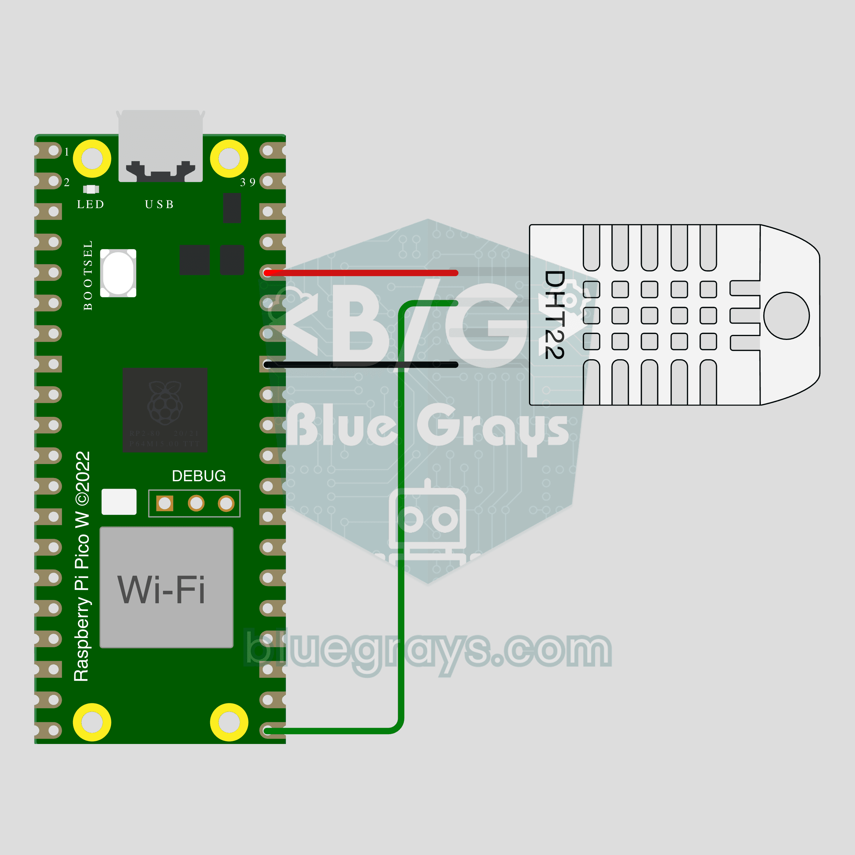
Pico W IoT Temperature and Humidity (DHT22)
Watch your room's temperature and humidity live on your phone wherever you are. This project is the step-by-step guide to the Temperature and humidity IoT template in the app, built with a Raspberry Pi Pico W and a DHT22. Go to Workshop › Devices › Add a device, pick Pico W as the board and Temperature and humidity as the template; Ohmi prepares the code with your own device key. The code on this page is an example: the key and Wi-Fi details are placeholders.
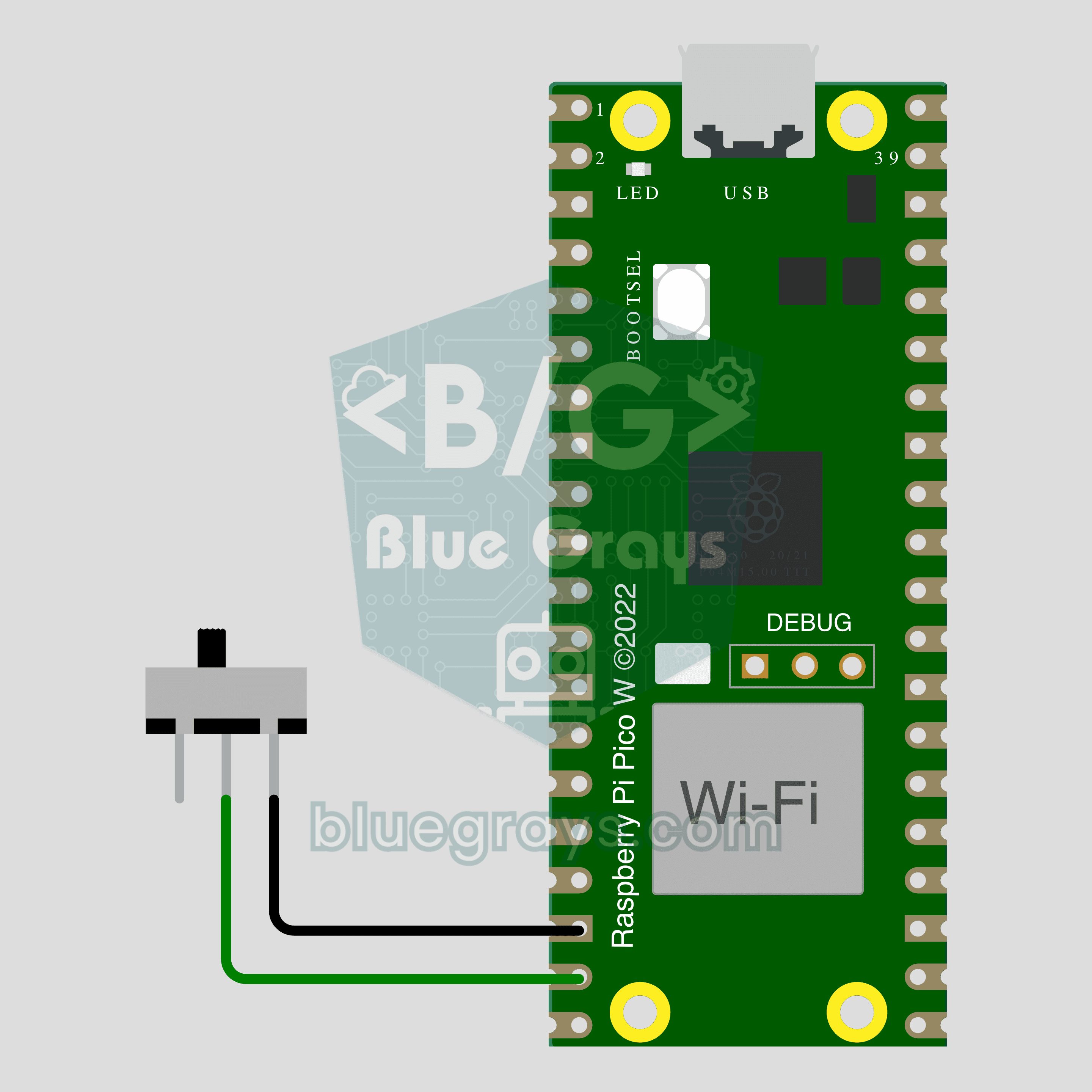
Pico W IoT Door Sensor (Reed Switch)
Did you leave the door or window open? Check on your phone wherever you are. This project is the step-by-step guide to the Door / window IoT template in the app, built with a Raspberry Pi Pico W, a reed switch and a small magnet using two wires. Go to Workshop › Devices › Add a device, pick Pico W as the board and Door / window as the template; Ohmi prepares the code with your own device key. The code on this page is an example: the key and Wi-Fi details are placeholders.
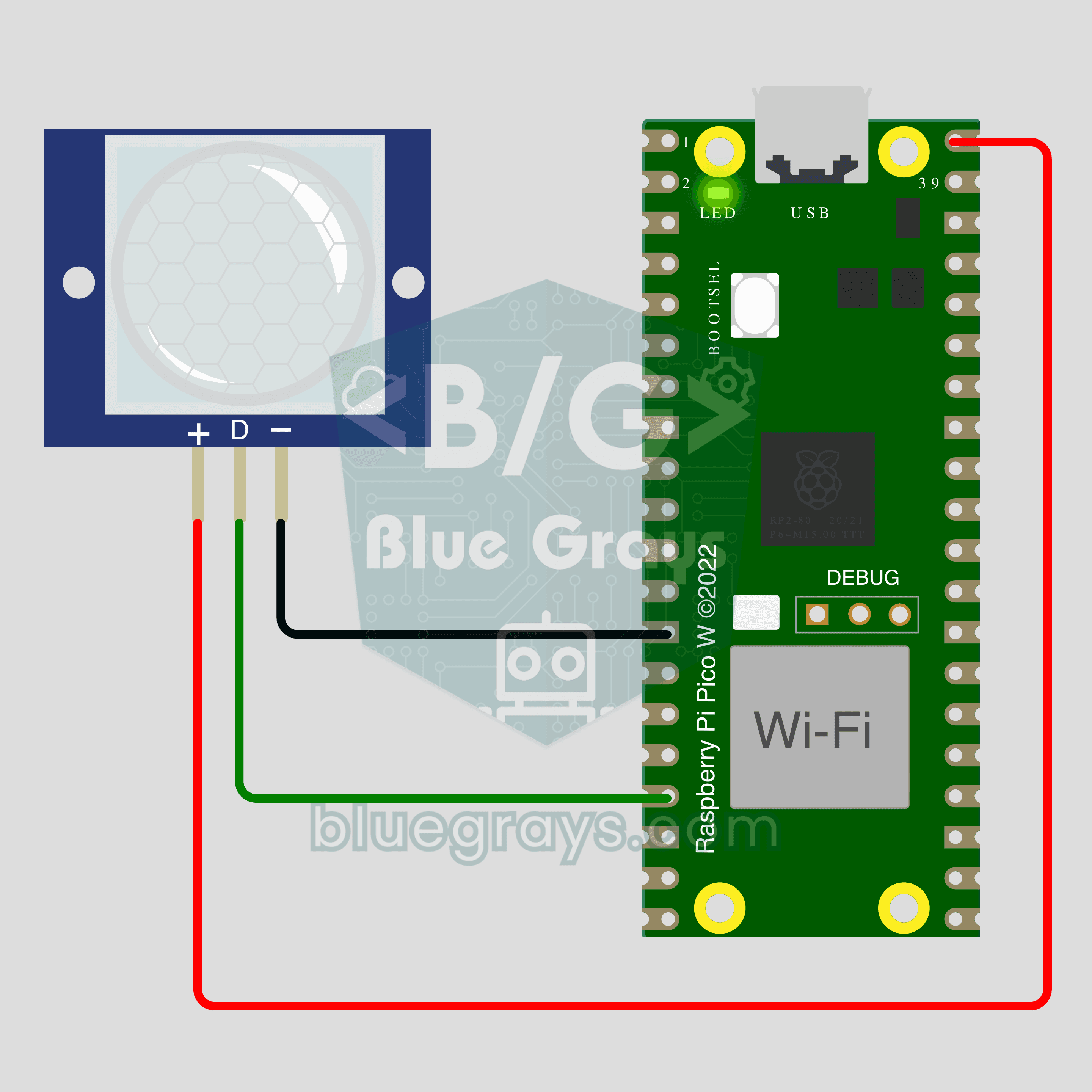
Pico W IoT Motion Counter (PIR)
Count how many times someone walks through a door or hallway, and see the moment of motion live on your phone. This project is the step-by-step guide to the Motion detector IoT template in the app, built with a Raspberry Pi Pico W and a PIR motion sensor using just 3 wires. Go to Workshop › Devices › Add a device; Ohmi prepares the code with your own device key. The code on this page is an example: the key and Wi-Fi details are placeholders.
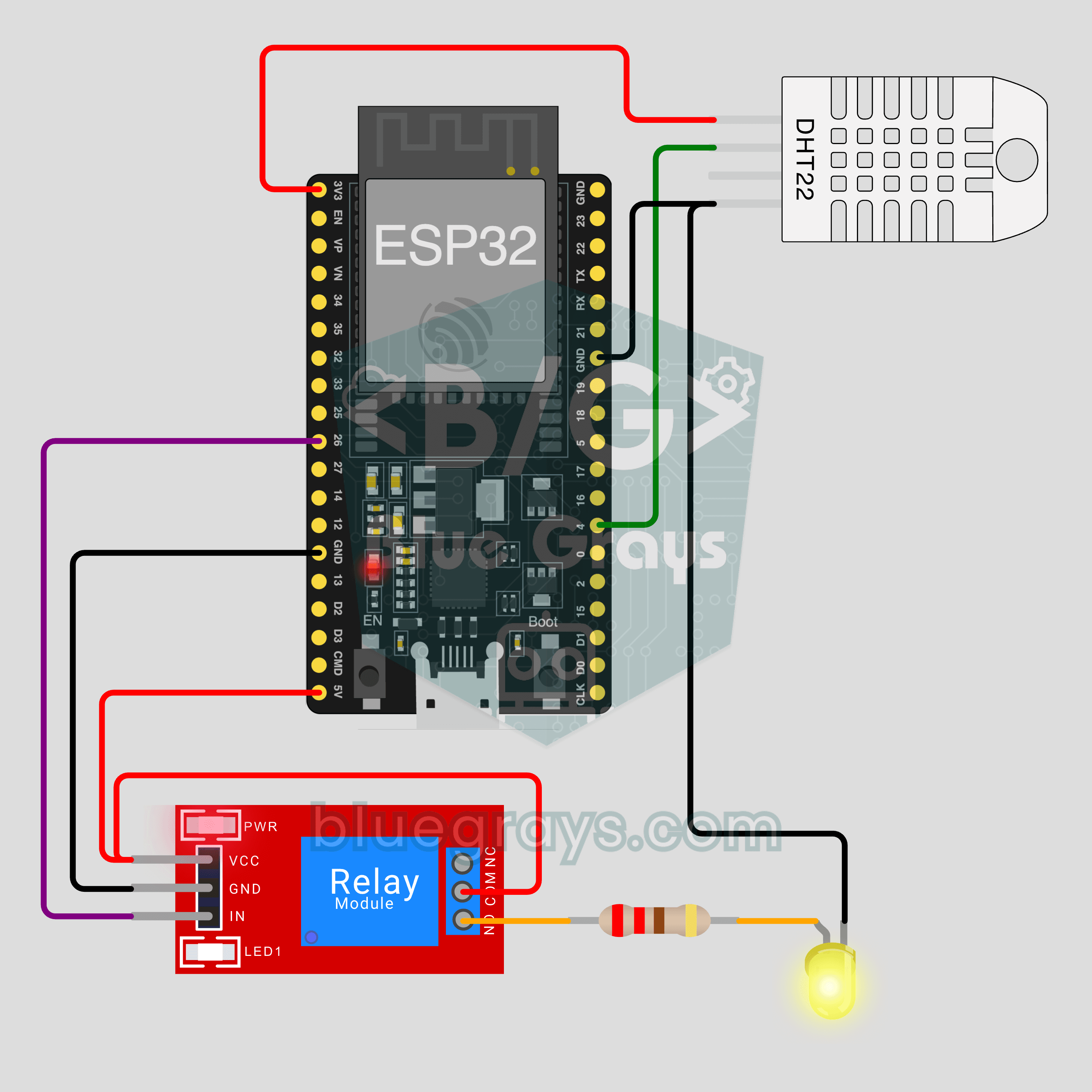
ESP32 IoT Room Station (Relay + DHT22)
Turn your lamp on from your phone and watch your room's temperature and humidity live, wherever you are. This project is the step-by-step guide to the Room station IoT template in the app, built with an ESP32, a relay module and a DHT22. Go to Workshop › Devices › Add a device and pick Room station; Ohmi prepares the code with your own device key. The code on this page is an example: the key and Wi-Fi details are placeholders.
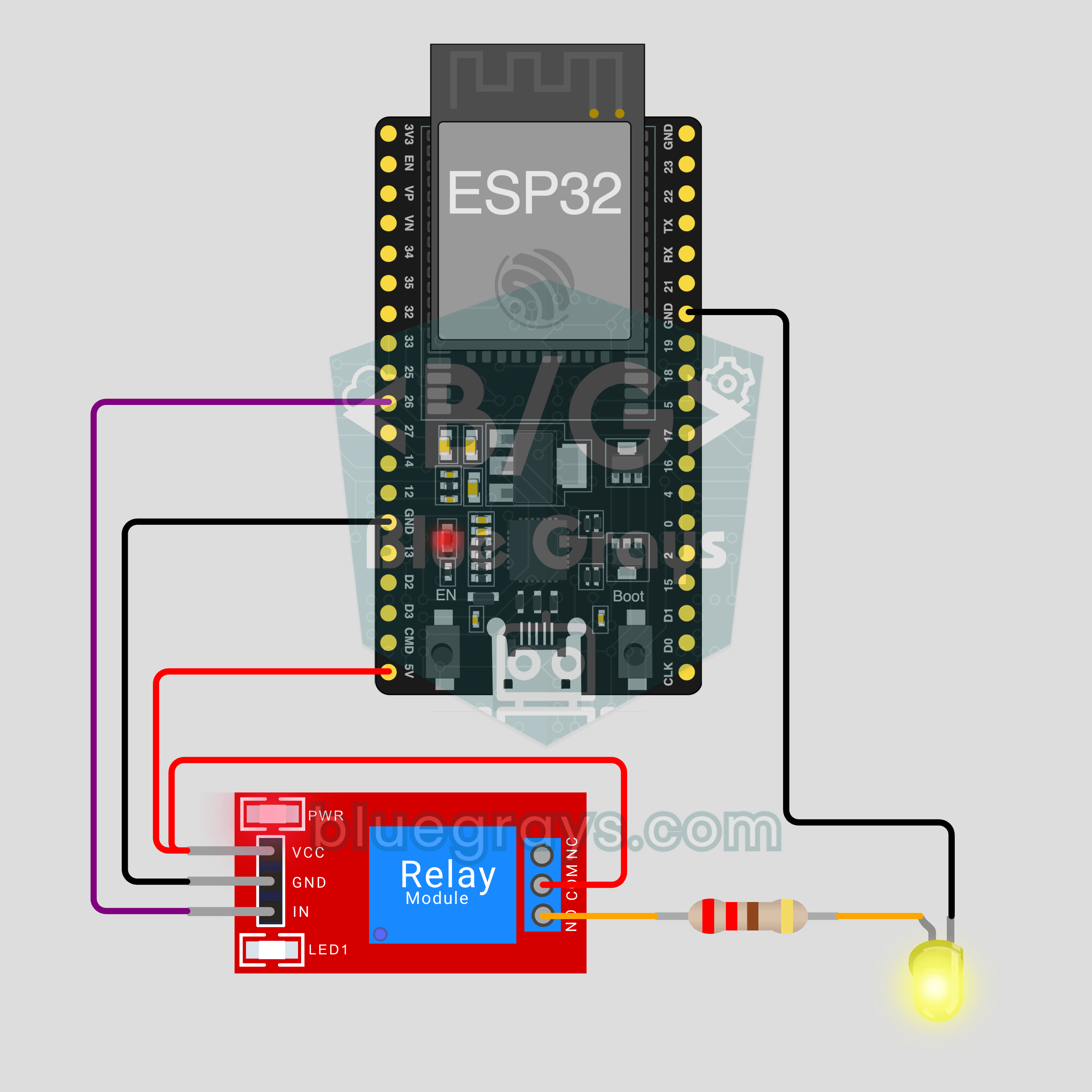
ESP32 IoT Lamp Switch (Relay)
Turn your lamp on and off from your phone, wherever you are. This project is the step-by-step guide to the Relay lamp IoT template in the app, built with an ESP32 and a relay module and tried with an LED first. Go to Workshop › Devices › Add a device and pick Relay lamp; Ohmi prepares the code with your own device key. The code on this page is an example: the key and Wi-Fi details are placeholders.
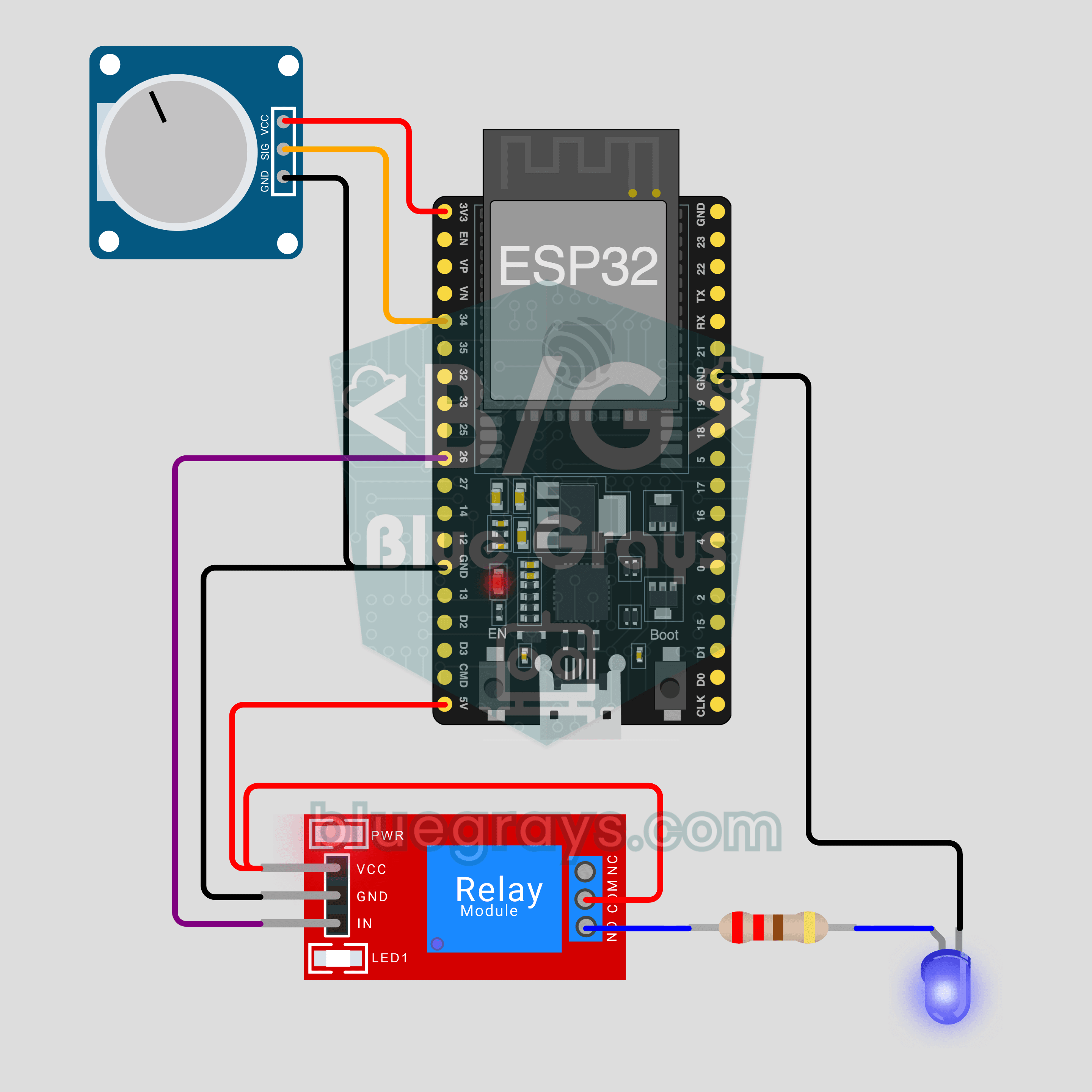
ESP32 IoT Plant Watering (Soil Sensor + Pump)
Let the pump start by itself when the soil in your pot dries out, and watch the soil moisture live on your phone. This project is the step-by-step guide to the Soil moisture + pump IoT template in the app, built with an ESP32, a soil moisture sensor, a relay and a mini water pump. Go to Workshop › Devices › Add a device; Ohmi prepares the code with your own device key. The code on this page is an example: the key and Wi-Fi details are placeholders.
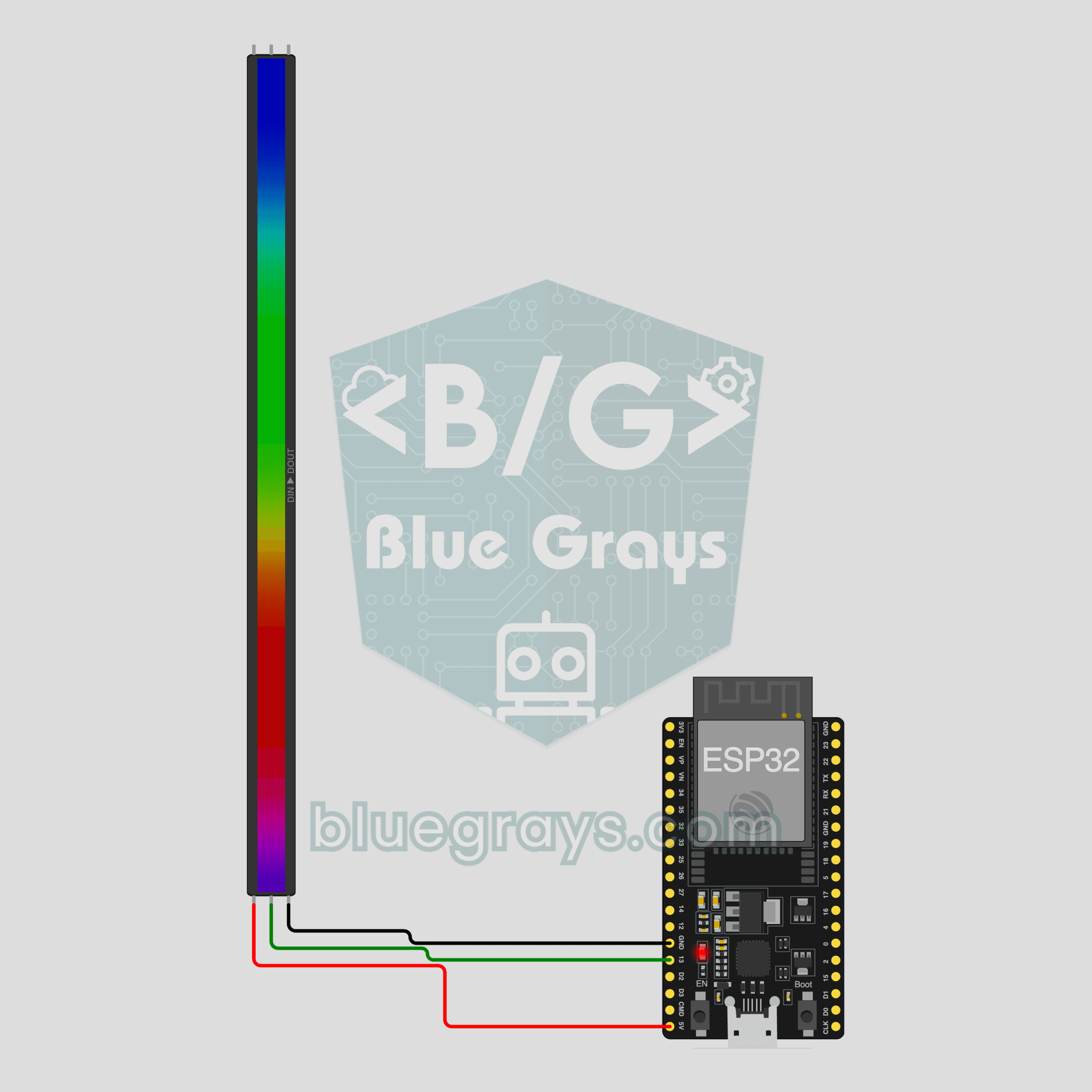
ESP32 IoT RGB LED Strip (WS2812B)
Control your room's light from your phone: pick a color, set the brightness, turn on the rainbow or breathe effect. This project is the step-by-step guide to the RGB LED strip IoT template in the app, built with an ESP32 and a 30-LED WS2812B strip using three wires. Go to Workshop › Devices › Add a device and pick RGB LED strip; Ohmi prepares the code with your own device key. The code on this page is an example: the key and Wi-Fi details are placeholders.
ESP32 IoT Curtain Opener (SG90 Servo)
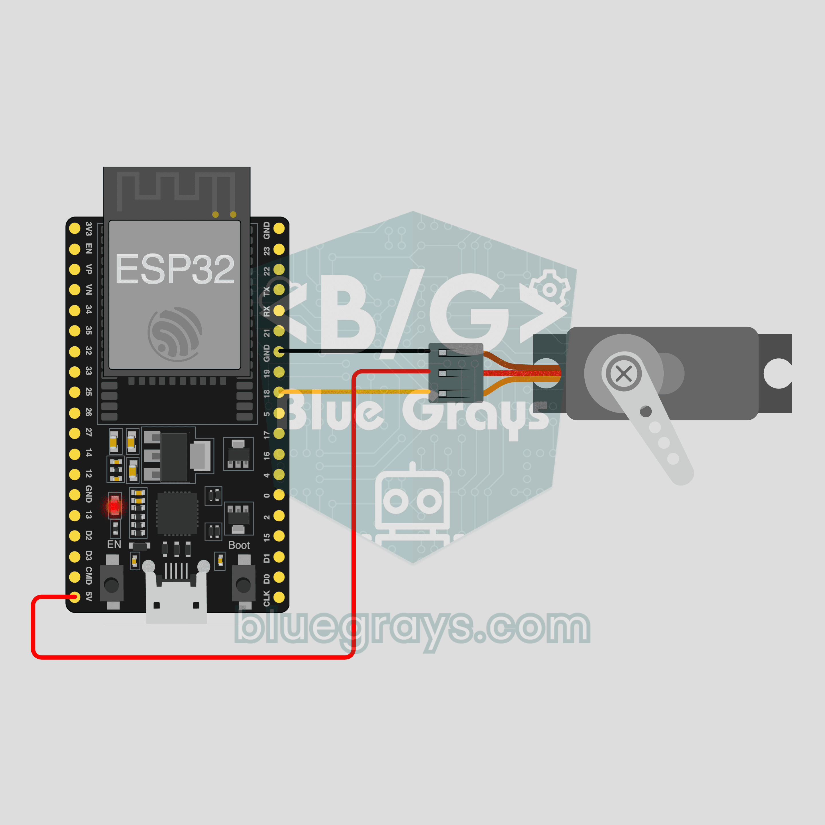
Tap + or − on your phone and the servo turns to that angle at the same moment: open and close a model curtain, a blind's tilt rod or a small lid from wherever you are. This project is the step-by-step guide to the Servo curtain IoT template in the app, built with an ESP32 and an SG90 servo using just 3 wires. Go to Workshop › Devices › Add a device; Ohmi prepares the code with your own device key. The code on this page is an example: the key and Wi-Fi details are placeholders.