
Control ESP32 from Your Phone: BlueGrays IoT Setup in 5 Steps
Control an ESP32 from your phone with BlueGrays IoT: relay and DHT22 wiring, code generated by Ohmi, 5 setup steps, live charts and fixes for common errors.
To control an ESP32 from your phone means switching a relay, LED or motor on the board on and off from the phone in your pocket, and seeing sensor readings on the screen. It is also the most fun first step into IoT. The ESP32 has 2.4 GHz Wi-Fi and Bluetooth built in, so you don't need any extra module. The real question is which approach you pick. For ESP32 app control you can write your own web server, connect over Bluetooth or set up a Telegram bot. Cloud dashboards such as Blynk and Arduino IoT Cloud are another option. Each method differs in setup time, range and limitations.
In this guide you'll build the quickest route step by step: the BlueGrays IoT feature in the BlueGrays app. Ohmi writes the code for you. All you do is build the circuit and upload the code to the ESP32 from the Arduino IDE. The board connects to the BlueGrays server over an encrypted connection, so your phone and the board don't need to be on the same network. You can switch on the lamp at home from work over mobile data. First you'll build a lamp switch with a relay. Then you'll add a DHT22 and bring temperature and humidity to your phone as live values and charts. At the end you'll find a comparison with the other methods and a troubleshooting table for the most common errors.
5 ways to control an ESP32 from your phone
- Local web server: The ESP32 serves a web page and you open the board's IP address in your phone's browser. No account needed, but normally it's only reachable from the same Wi-Fi network. Details in the ESP32 Async Web Server post.
- Bluetooth Classic and BLE: No internet or router needed; the phone connects directly to the board. Indoor range is usually around 10 meters. We cover both types in the ESP32 Bluetooth guide.
- Telegram bot: You send commands to the board by message and get notifications back. It works from outside your home too, but offers no dashboard with charts or sliders. See the ESP32 Telegram Bot post for setup.
- Cloud dashboards (Blynk, Arduino IoT Cloud): You define templates and variables in a web console, write the code yourself and design the phone dashboard yourself. It's flexible, but you have to learn several separate screens and concepts. For Blynk, our Blynk ESP32 Guide is ready.
- BlueGrays IoT: You pick one of 8 ready-made templates in the app. Ohmi generates the code with your pin settings and device key. Switches, sliders, a color picker and charts appear on the phone automatically based on the template. No dashboard to design, no server to set up.
What you need: parts and software
| Item | What it's for | Note |
|---|---|---|
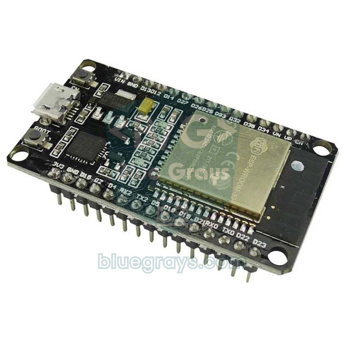
| ESP32 development board | Wi-Fi microcontroller | ESP32 Dev Module, WROOM, S3 and C3 are supported |
| USB data cable | Uploading code and power | A charge-only cable won't show a port |
| 5 V relay module | Switching the lamp | Prefer an optocoupler module that triggers on a 3.3 V signal |
| LED + 220 Ω resistor | Safe first test instead of the relay | Set RELAY_ACTIVE_LOW = false in the code |
| DHT22 (optional) | Measuring temperature and humidity | For the Room station template |
| Breadboard and jumper wires | Making the connections | Male-to-female wires are handy for modules |
| 2.4 GHz Wi-Fi network | Internet access for the board | The board won't connect to a 5 GHz network |
| Arduino IDE | Uploading code to the board | Requires the Espressif esp32 core version 3.x |
| BlueGrays app | Setup and phone control | iOS and Android; your first device is free |
How does ESP32 app control work?
With BlueGrays IoT, the phone and the ESP32 don't connect to each other directly. When the board starts, it first joins your home 2.4 GHz Wi-Fi network. It then opens an encrypted WebSocket (TLS) connection to the BlueGrays server over port 443 and keeps it open. The app on your phone connects to the same server. When you tap the lamp switch, the command travels from the phone to the server and from the server to the board. Because the connection is already open, the command arrives without delay. The temperature value the board sends follows the same path in reverse. Port 443 is the same port websites use, so you don't need port forwarding on your router, your own server or the board's IP address.
What identifies the board to the server is the device key. It's a secret string starting with bgd_ that the app generates when you create the device. The board sends the key in the connection header when it connects, and the server routes commands from your phone to the right board. The key is never printed to the Serial Monitor. If the connection drops, the BlueGraysIoT library retries on its own at increasing intervals. Readings taken while offline are sent once it reconnects, and after a power cut the switches are restored to their last state. All that's needed is internet access for both the board and the phone: the board can be on your home Wi-Fi while your phone is on mobile data in another city.
Wiring: connecting the relay module to the ESP32
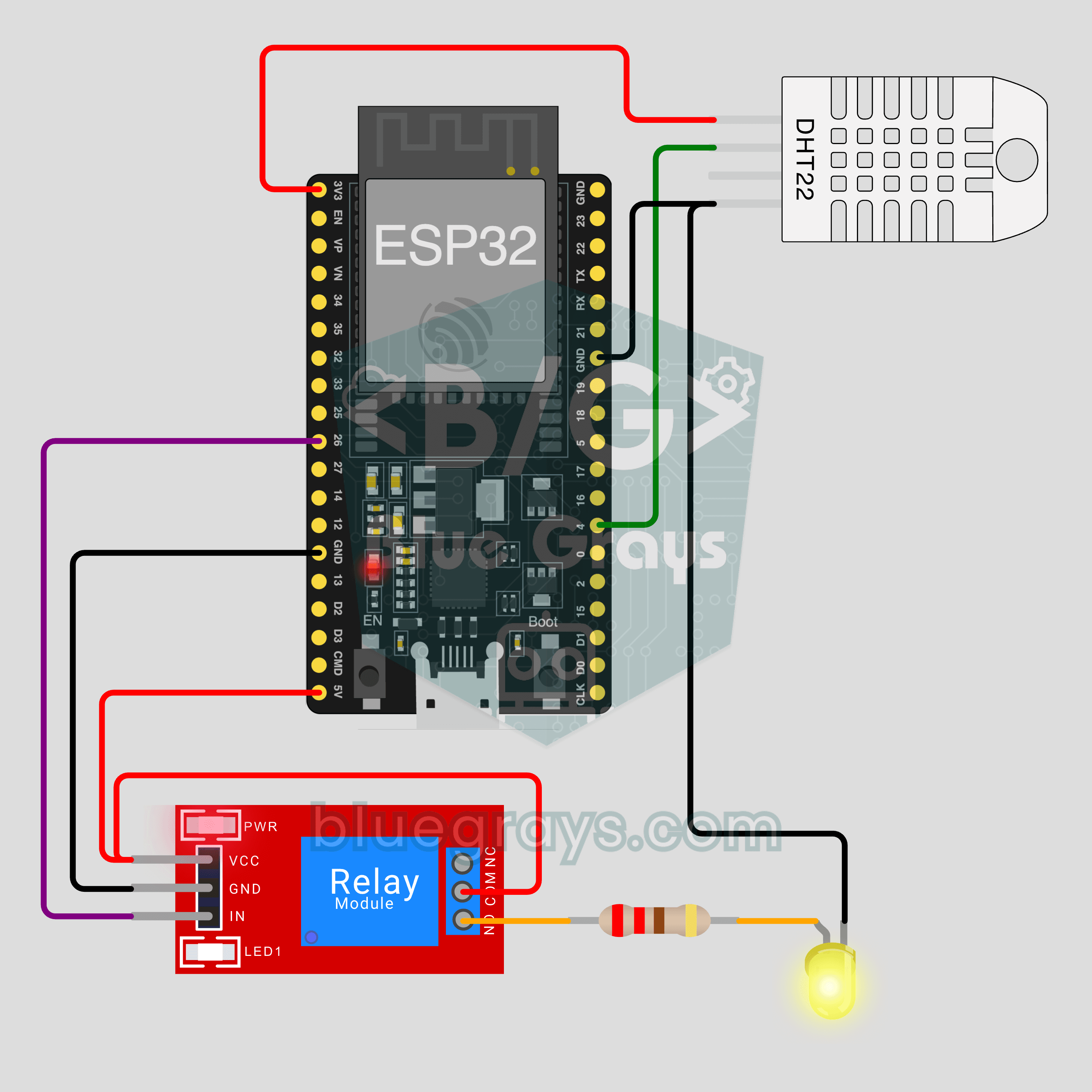
In the Relay lamp and Room station templates the default pins are: relay IN to GPIO26 and the DHT22 data pin to GPIO4. You can change these pins in step 3 of the setup. Check your board's pin layout with the Pinout tool. Some boards label the 5 V pin VIN, others 5V.
| Part | Part pin | ESP32 pin | Note |
|---|---|---|---|
| Relay module | VCC | 5V (VIN) | The coil needs 5 V; this pin carries about 5 V when the board is USB-powered |
| Relay module | GND | GND | Common ground |
| Relay module | IN | GPIO26 | 3.3 V control signal |
| LED (for testing) | Long leg (+) | GPIO26 | With a 220 Ω resistor; short leg to GND, RELAY_ACTIVE_LOW = false in the code |
| DHT22 | VCC | 3V3 | For the Room station |
| DHT22 | DATA | GPIO4 | A bare sensor needs a 10 kΩ pull-up; modules have it on board |
| DHT22 | GND | GND | Common ground |
BlueGrays IoT setup: the 5 steps in the app
In the app, go to Workshop › My devices › Add new device. You'll see a counter such as "Step 1 of 5" at the top of the screen. The first three steps happen on the phone, step four on your computer, and step five back on the phone.
- Board and template: Under "Which board?" choose ESP32, and under "What will it do?" pick one of the 8 templates. For a first try, "Relay lamp" or the sensor-based "Room station" is a good start. Give the device a name you'll easily recognize, like "Living room lamp".
- Parts and wiring: The "Get your parts ready" list shows the parts the template needs, and the "Connect the wires" diagram shows which lead goes to which pin. Relay templates show the warning "If you'll be working with 230 V, do it with someone who knows how. Test with an LED first."
- Wi-Fi and code: Enter your Wi-Fi network name and password. The network name must match exactly and belong to the 2.4 GHz band. If you like, swap GPIO26 and GPIO4 for other pins in the "Connection pins" section. Then tap "Create device and generate code". Ohmi generates the code with your device key; use "Copy code" or "Share" to get it onto your computer.
- Upload with the Arduino IDE: You upload the code to the ESP32. We go through the sub-steps from the app one by one in the next section.
- Connection: The "Waiting for your board" screen moves on automatically as soon as the board connects to the server.
Steps 4 and 5: uploading the code and confirming the connection
- Install the Arduino IDE if you haven't already. The steps are in the Arduino IDE Installation post.
- In Boards Manager, search for "esp32" and install the esp32 package by Espressif. You need version 3.x; if the old 2.x version is installed, update it. Installing the package is also covered in What Is ESP32?.
- Plug in the board with a USB cable that carries data. Choose ESP32 Dev Module (or your board's model) under Tools › Board, and the newly appeared port under Tools › Port. If no port shows up, try another cable. Then install the CP210x or CH340 driver depending on your board's USB chip.
- In Library Manager, search for BlueGraysIoT and click Install. When it asks about dependencies, choose "Install all" so WebSockets, ArduinoJson and DHT sensor library are installed too. If you get stuck, see the How to Add an Arduino Library guide.
- Open a new sketch, delete its contents, paste the code you copied from the app and click Upload. If the output pane hangs on "Connecting…", hold down the BOOT button on the board and release it once the write percentages start to appear.
- Open the Serial Monitor and set the baud rate to 115200. You should first see "Wi-Fi connected", then a few seconds later "BlueGrays IoT: connected".
As soon as the connected line appears in the Serial Monitor, the "Waiting for your board" screen on your phone switches to "Connected: values now arrive in real time." Now tap the lamp switch: you should hear the relay click or see the LED light up. If the board doesn't connect within 2 minutes, the app asks you to check three things. Did you pick the 2.4 GHz network? Does the Serial Monitor show "Wi-Fi connected"? Is the password's upper and lower case correct? If the first line never appears, the problem is on the Wi-Fi side. In that case the checklist in the ESP32 Won't Connect to WiFi post will sort you out.
First sketch: turning a lamp on and off from your phone
The code the app generates for the "Relay lamp" template looks like the one below. The top three lines come filled with your device key, network name and password; here they're shown as placeholders. The rest is short: one relay function, one switch definition and a one-line loop().
1/*
2 * Salon lambası · BlueGrays IoT
3 * BlueGrays · bluegrays.com
4 * Bu kodu paylaşma: içinde cihaz anahtarın ve Wi-Fi şifren var.
5 * Do not share this code: it contains your device key and Wi-Fi password.
6 */
7
8#include <BlueGraysIoT.h>
9
10// Uygulama bu üç satırı senin bilgilerinle doldurur / The app fills these three lines with your details
11const char *DEVICE_KEY = "bgd_UYGULAMADAKI_ANAHTARIN";
12const char *WIFI_NAME = "EV_AGI_2_4_GHZ";
13const char *WIFI_PASSWORD = "WIFI_SIFREN";
14
15BlueGraysIoT bg(DEVICE_KEY);
16
17const int RELAY_PIN = 26;
18const bool RELAY_ACTIVE_LOW = true;  // çoğu röle modülü LOW ile çeker / most relay modules switch on LOW
19void setRelay(bool on) { digitalWrite(RELAY_PIN, (on != RELAY_ACTIVE_LOW) ? HIGH : LOW); }
20
21void setup() {
22  Serial.begin(115200);
23  pinMode(RELAY_PIN, OUTPUT);
24  setRelay(false);                  // açılışta lamba kapalı / lamp off at power-up
25  bg.onSwitch("lamba", setRelay);   // uygulamadaki "Lamba" anahtarı / the "Lamba" switch in the app
26  bg.setDebug(Serial);              // durum mesajları Seri Port Ekranı'na / status messages to the Serial Monitor
27  bg.setLanguage(BG_LANG_TR);
28  bg.begin(WIFI_NAME, WIFI_PASSWORD);
29}
30
31void loop() {
32  bg.loop();  // burada uzun delay() kullanma / avoid long delay() calls here
33}
34| Line | What it does |
|---|---|
| #include | Includes the library; it handles Wi-Fi, the encrypted connection and reconnecting |
| DEVICE_KEY, WIFI_NAME, WIFI_PASSWORD | Device key (starts with bgd_), 2.4 GHz network name and password; filled in by the app |
| BlueGraysIoT bg(DEVICE_KEY) | Creates the bg object with the key; every other command goes through this object |
| RELAY_PIN = 26 | Pin the relay IN lead is connected to; if you changed the pin in step 3, you'll see a different number here |
| RELAY_ACTIVE_LOW = true | Most relay modules trigger on a LOW signal; set it to false when testing with an LED, otherwise it works inverted |
| setRelay(bool on) | When on is true it writes the active level: LOW on an active-low module, HIGH otherwise |
| setRelay(false) (in setup) | The lamp starts off when the board powers up |
| bg.onSwitch("lamba", setRelay) | Calls setRelay with true or false every time the Lamp switch in the app changes |
| bg.setDebug(Serial) | Prints connection status messages to the Serial Monitor |
| bg.setLanguage(BG_LANG_TR) | Prints status messages in Turkish |
| bg.begin(WIFI_NAME, WIFI_PASSWORD) | Starts connecting to the Wi-Fi network and the BlueGrays server |
| bg.loop() | Processes incoming commands and keeps the connection alive; must be called continuously inside loop() |
Adding a sensor: Room station (relay + DHT22)
Now let's add a DHT22 to the same board and send data to the phone. If you choose the "Room station" template in the app, you get temperature (°C) and humidity (%) values and charts next to the lamp switch. The DHT22 measures from -40 to 80 °C with about ±0.5 °C accuracy. It measures humidity across 0–100% and can be read at most once every 2 seconds. Connect the data pin to GPIO4, VCC to 3V3 and GND to GND. We compare how the DHT family works in the DHT11 Temperature and Humidity Sensor post.
1/*
2 * Oda istasyonu · BlueGrays IoT
3 * BlueGrays · bluegrays.com
4 * Bu kodu paylaşma: içinde cihaz anahtarın ve Wi-Fi şifren var.
5 * Do not share this code: it contains your device key and Wi-Fi password.
6 */
7
8#include <BlueGraysIoT.h>
9#include <DHT.h>
10
11const char *DEVICE_KEY = "bgd_UYGULAMADAKI_ANAHTARIN";
12const char *WIFI_NAME = "EV_AGI_2_4_GHZ";
13const char *WIFI_PASSWORD = "WIFI_SIFREN";
14
15BlueGraysIoT bg(DEVICE_KEY);
16
17const int RELAY_PIN = 26;
18const bool RELAY_ACTIVE_LOW = true;  // çoğu röle modülü LOW ile çeker / most relay modules switch on LOW
19void setRelay(bool on) { digitalWrite(RELAY_PIN, (on != RELAY_ACTIVE_LOW) ? HIGH : LOW); }
20DHT dht(4, DHT22);                   // DHT22 veri ucu GPIO4 / DHT22 data on GPIO4
21unsigned long lastReadMs = 0;
22
23void setup() {
24  Serial.begin(115200);
25  pinMode(RELAY_PIN, OUTPUT);
26  setRelay(false);
27  bg.onSwitch("lamba", setRelay);
28  dht.begin();
29  bg.setDeadband("sicaklik", 0.1);   // 0,1 °C değişmeden gönderme / send only after a 0.1 °C change
30  bg.setDeadband("nem", 1.0);        // %1 değişmeden gönderme / send only after a 1 % change
31  bg.setDebug(Serial);
32  bg.setLanguage(BG_LANG_TR);
33  bg.begin(WIFI_NAME, WIFI_PASSWORD);
34}
35
36void loop() {
37  bg.loop();  // burada uzun delay() kullanma / avoid long delay() calls here
38  if (millis() - lastReadMs >= 2000) {  // DHT22 en fazla 2 saniyede bir okunur / DHT22 reads at most every 2 s
39    lastReadMs = millis();
40    bg.send("sicaklik", dht.readTemperature());
41    bg.send("nem", dht.readHumidity());
42  }
43}
44
The relay part is the same as in the first sketch; there are three new things. The first is the line bg.send("sicaklik", dht.readTemperature()): it sends a value from the board to the app, and the first parameter is the variable name in the app. The second is bg.setDeadband("sicaklik", 0.1). It sets the minimum change: temperature isn't resent until it changes by 0.1 °C, and for humidity this margin is 1%. The third is the millis() - lastReadMs >= 2000 check inside loop. The sensor is read every 2 seconds, but bg.loop() keeps running in between without waiting. The library only sends a value when it changes and never exceeds the plan rate. For the same variable, at least 1 second passes between two sends on the free plan and at least 0.2 seconds on Premium. These limits are enforced on the server; changing the numbers in the code won't get around them. If the room stays at 23.4 °C for minutes, the board sends nothing new; when it hits 23.5 °C, a single message goes out. If a wire is loose or the pull-up is missing, the reading is invalid (NaN). If no values arrive, check the GPIO4 connection and the power supply first.
What you see on your phone
- Status: The top of the device screen shows Online or Offline, with "Last data … ago" below it. This is the first place to check whether the board is really connected.
- Controls: The lamp template shows an on/off switch. The RGB strip template gets a color picker, 0–100% brightness and an effect selector. The curtain template has a 0–180° angle slider.
- Live values and charts: Ranges are 1 h, 24 h, 7 days and 30 days. The 7- and 30-day views show hourly averages. The chart displays the Lowest, Highest and Latest values. As long as the board stays connected, a new point is added every minute.
- Code and key: You can view the full code, device key and Wi-Fi details here later too. If you need to reflash the board, copy the code from here.
- Regenerate key: Use it if someone has seen your key or you've swapped the board. The old key stops working immediately; you just upload the new code to the board once.
- Remove device: The device and its chart history are deleted, and your device slot is freed up.
Free vs Premium: how much can you use?
Your first device is free. You need nothing else to build a lamp switch or room station with one ESP32. In the Room station, temperature and humidity are two separate variables. On the free plan you get live values for both on your phone, but chart history is kept for only one variable. The differences between the plans are below; details in the What Does BlueGrays Premium Unlock? post.
| Feature | Free | Premium |
|---|---|---|
| Number of devices | 1 | 10 |
| Variables with chart history | 1 | 20 |
| History length | 24 hours | 30 days |
| Minimum time between two sends of the same variable | 1 second | 0.2 seconds |
Comparison with other methods
| Method | Access from outside home | Your work during setup | Dashboard and charts | Best for |
|---|---|---|---|---|
| Local web server | Normally no, same network only | Writing ESP32 code and an HTML page | You design it yourself | Offline in-home control panel |
| Bluetooth / BLE | No, about 10 m | Board code plus an app on the phone side | Depends on the app you use | Places without a router, close-range control |
| Telegram bot | Yes | Creating the bot and writing the code | Messages and buttons, no charts | Notifications and simple commands |
| Blynk | Yes | Template, datastreams, dashboard and code | Ready-made widgets and charts | People who want to design their own dashboard |
| Arduino IoT Cloud | Yes | Defining a Thing and variables in your Arduino account, completing the code | Dashboard widgets | Those staying in the Arduino ecosystem |
| BlueGrays IoT | Yes | Building the circuit and uploading the code | Ready-made controls and charts per template | Getting started fast and using it while learning |
The right choice depends on what you need. If there's no internet at all, Bluetooth or a local web server is your only option. BlueGrays IoT, Blynk and Arduino IoT Cloud need internet access for both the board and the phone. If you want flexible setups, like designing the interface from scratch or connecting to Home Assistant, ESP32 MQTT and cloud dashboards give you more options. BlueGrays IoT has 8 ready-made templates. In return, the wiring diagram, parts list, code and phone interface all come ready and matched to each other, so you're less likely to make a mistake somewhere while learning.
Security: key, Wi-Fi password and code
- The device key is your board's identity. Anyone who knows your bgd_ key can impersonate your board. So don't share the key in screenshots, forums or chat groups.
- Your Wi-Fi password stays on the phone. The password isn't sent to the server; the network name is stored with the device so the code can be shown again later. But the password is written inside the code uploaded to the board.
- Don't share the code. As the app also warns, the code contains your device key and Wi-Fi password. If you'll post the code on a forum to ask for help, delete the DEVICE_KEY, WIFI_NAME and WIFI_PASSWORD lines first.
- The connection is encrypted. Traffic between the board and the server goes over TLS on port 443, so someone on the same network can't read the commands.
- Regenerate the key if in doubt. The Regenerate key button invalidates the old key immediately. If you're giving the board to someone else, regenerate the key or remove the device too.
Common errors and fixes
| Symptom | Likely cause | Fix |
|---|---|---|
| "Wi-Fi connected" never appears in the Serial Monitor | A 5 GHz network was selected or the password has a case error | Enter the 2.4 GHz network name; if the router's bands share one name, split them; retype the password carefully |
| No port under Tools › Port | Charge-only cable or missing driver | Use a data cable; install the CP210x or CH340 driver for your chip |
| Upload hangs on "Connecting…" | The board isn't entering upload mode | Hold the BOOT button and release it once writing starts; more in the Arduino Code Won't Upload post |
| Compilation stops with ESP32 core errors | The old 2.x version of the esp32 package is installed | Update to version 3.x in Boards Manager |
| "No such file or directory" (BlueGraysIoT.h, DHT.h, WebSockets) | The library or its dependencies aren't installed | Reinstall BlueGraysIoT and choose "Install all"; search for any missing one by name |
| Garbage characters in the Serial Monitor | Baud rate isn't 115200 | Set the Serial Monitor to 115200 baud |
| "Wi-Fi connected" appears but no "BlueGrays IoT: connected" | The network has no internet, a corporate network is blocking it, or code from before a key regeneration is uploaded | Try your phone's hotspot; upload the current code from the Code and key screen |
| The board resets when the relay clicks | Insufficient power (brownout) | Use a good cable and a strong adapter, power the relay from 5V; see ESP32 Brownout |
| The LED is on while the switch is off | RELAY_ACTIVE_LOW left at true for the relay | If you're driving an LED directly, set RELAY_ACTIVE_LOW = false |
| An analog sensor reads the same value once Wi-Fi is on | The sensor is on an ADC2 pin | Use one of the ADC1 pins (GPIO32–39); details in the What Is an ADC? post |
| Temperature and humidity values don't arrive | DHT22 data pin on the wrong pin or missing pull-up | Connect DATA to GPIO4 and VCC to 3V3; add a 10 kΩ pull-up on a bare sensor |
ESP32 IoT project ideas you can build
- Lamp switch: The complete version of the first circuit in this post is the ESP32 IoT Lamp Switch (Relay) project. It comes with a wiring diagram and parts list.
- Room station: Relay and DHT22 together, with a temperature chart: ESP32 IoT Room Station (Relay + DHT22).
- Plant watering: The soil moisture sensor connects to GPIO34 (an ADC1 pin). When moisture drops below the Watering threshold slider on your phone, the pump turns on, and it turns off once moisture rises 10 points above the threshold. Project page: ESP32 IoT Plant Watering (Soil Sensor + Pump). For sensor calibration, also see the Soil Moisture Sensor post.
- RGB LED strip: Pick the color, brightness and effect (Solid, Rainbow, Breathe, Blink) of a 30-LED WS2812B strip on GPIO13 from your phone: ESP32 IoT RGB LED Strip (WS2812B). 30 LEDs at full white can draw about 1.8 A; power the strip from a separate 5 V supply. Details in the WS2812B NeoPixel post.
- Curtain opener: Turn an SG90 servo on GPIO18 with a 0–180° slider: ESP32 IoT Curtain Opener (SG90 Servo). Power the servo from a separate 5 V supply too and tie the GNDs together.
- Other templates: The door sensor, motion counter and temperature and humidity projects are built with the Pico W. You can also choose these templates for the ESP32 in the app.
Once you've set up the path between board, server and phone, adding a new device takes just a few minutes. Start with the lamp switch, then watch data flow to your phone with the DHT22, and move on to bigger projects like watering or a curtain opener. In the BlueGrays app you can explore these ESP32 IoT projects step by step with wiring diagrams and code. Use the IoT projects filter in Explore, and connect the same circuit straight to your phone with the "Set up as IoT device" card on the project page.
Frequently asked questions
How do I control an ESP32 from my phone?
You can control an ESP32 from your phone with a local web server, Bluetooth, a Telegram bot or a cloud dashboard. With BlueGrays IoT you go to Workshop › My devices › Add new device, choose the board and template, enter your Wi-Fi details and upload the code Ohmi generates using the Arduino IDE. Once the board connects, switches and values appear on your phone.
Can I control an ESP32 from my phone without internet?
Not with BlueGrays IoT; both the board and the phone need internet access, because commands travel through the server. For offline control you can use Bluetooth (BLE) or an ESP32 web server on the same network.
Can I control my ESP32 from another city?
Yes. Because the board and phone connect to the same server, they don't need to be on the same network. The board can be on your home 2.4 GHz Wi-Fi while your phone uses mobile data. No port forwarding, static IP or server of your own is needed.
Is BlueGrays IoT free?
Your first device is free. The free plan includes 1 device, chart history for 1 variable and 24 hours of history. Premium unlocks 10 devices, chart history for 20 variables and up to 30 days of history.
Should I control my ESP32 over Bluetooth or Wi-Fi?
Bluetooth needs no internet or router, but its indoor range is usually around 10 meters. With Wi-Fi and a server you can manage the board from anywhere in the world, and charts and history are kept. Bluetooth suits you if you're always nearby with no router; Wi-Fi is better if you want remote access.
How many devices can I connect to BlueGrays IoT?
You can add 1 device on the free plan and 10 on Premium. Supported boards are the ESP32 (Dev Module, WROOM, S3, C3) and the Raspberry Pi Pico W. Removing a device frees up its slot.
Projects to build after reading this
See all projects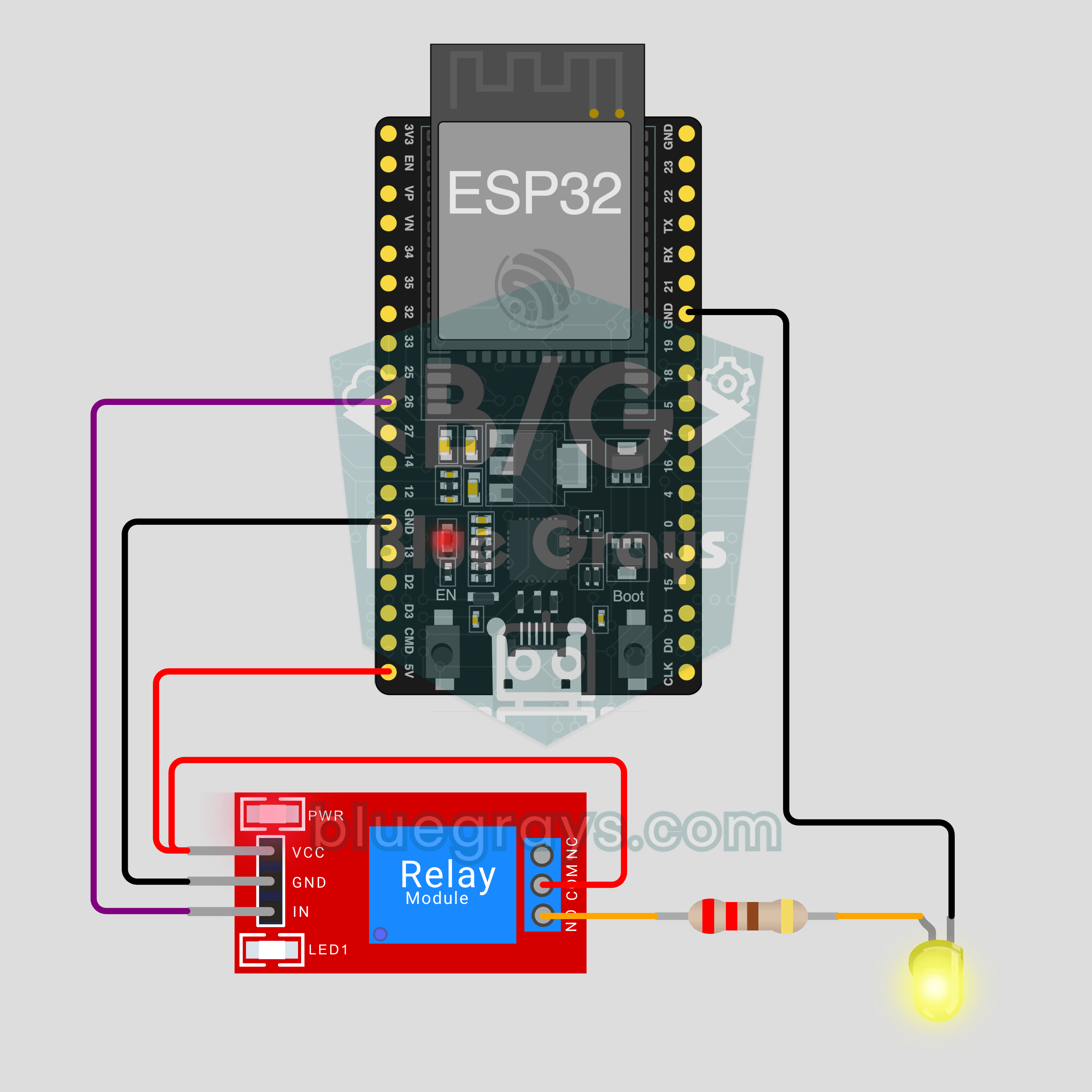
ESP32 IoT Lamp Switch (Relay)
Turn your lamp on and off from your phone, wherever you are. This project is the step-by-step guide to the Relay lamp IoT template in the app, built with an ESP32 and a relay module and tried with an LED first. Go to Workshop › Devices › Add a device and pick Relay lamp; Ohmi prepares the code with your own device key. The code on this page is an example: the key and Wi-Fi details are placeholders.
ESP32 IoT Room Station (Relay + DHT22)
Turn your lamp on from your phone and watch your room's temperature and humidity live, wherever you are. This project is the step-by-step guide to the Room station IoT template in the app, built with an ESP32, a relay module and a DHT22. Go to Workshop › Devices › Add a device and pick Room station; Ohmi prepares the code with your own device key. The code on this page is an example: the key and Wi-Fi details are placeholders.
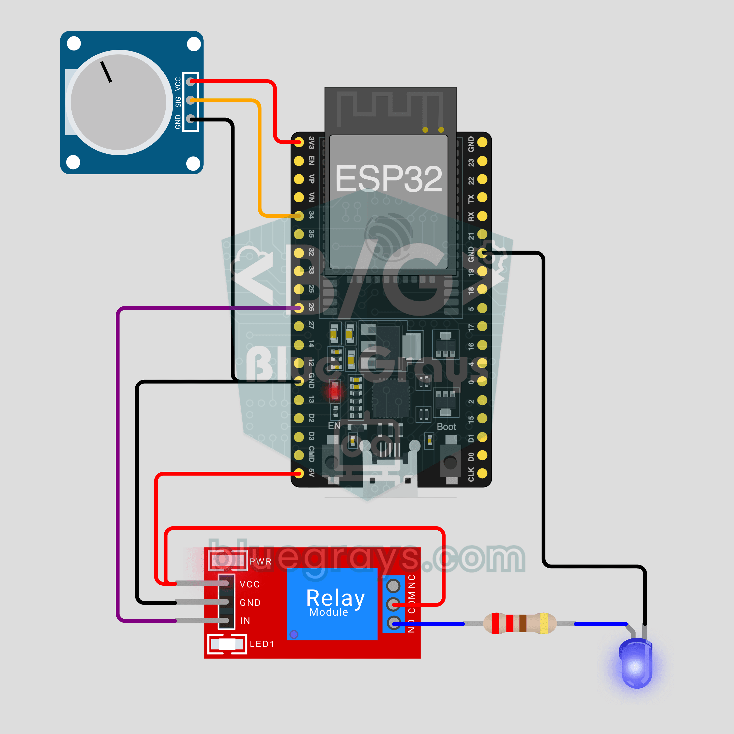
ESP32 IoT Plant Watering (Soil Sensor + Pump)
Let the pump start by itself when the soil in your pot dries out, and watch the soil moisture live on your phone. This project is the step-by-step guide to the Soil moisture + pump IoT template in the app, built with an ESP32, a soil moisture sensor, a relay and a mini water pump. Go to Workshop › Devices › Add a device; Ohmi prepares the code with your own device key. The code on this page is an example: the key and Wi-Fi details are placeholders.
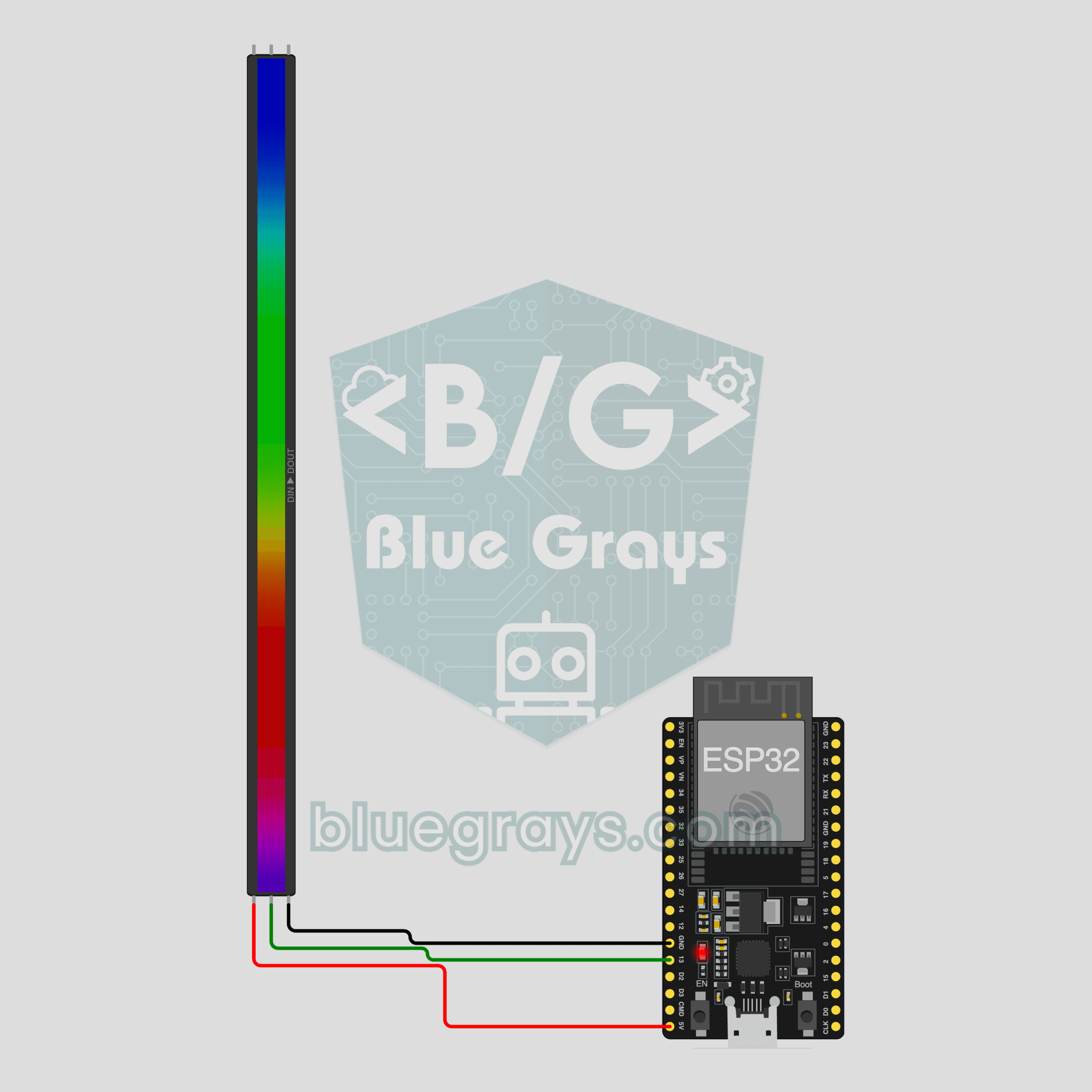
ESP32 IoT RGB LED Strip (WS2812B)
Control your room's light from your phone: pick a color, set the brightness, turn on the rainbow or breathe effect. This project is the step-by-step guide to the RGB LED strip IoT template in the app, built with an ESP32 and a 30-LED WS2812B strip using three wires. Go to Workshop › Devices › Add a device and pick RGB LED strip; Ohmi prepares the code with your own device key. The code on this page is an example: the key and Wi-Fi details are placeholders.
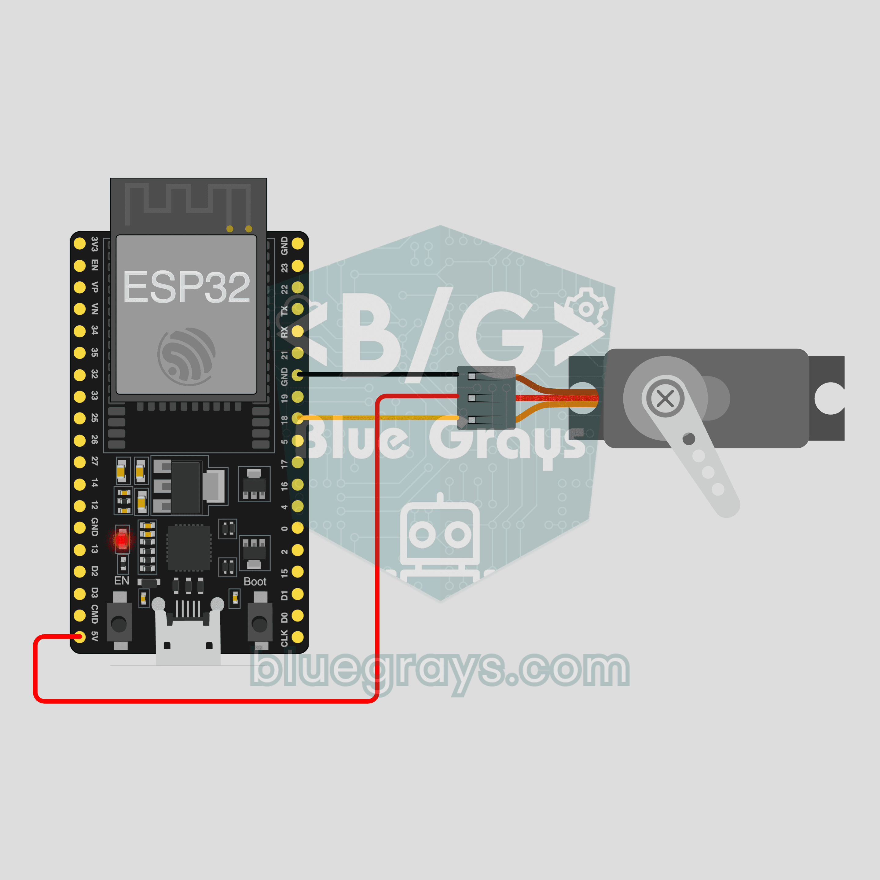
ESP32 IoT Curtain Opener (SG90 Servo)
Tap + or − on your phone and the servo turns to that angle at the same moment: open and close a model curtain, a blind's tilt rod or a small lid from wherever you are. This project is the step-by-step guide to the Servo curtain IoT template in the app, built with an ESP32 and an SG90 servo using just 3 wires. Go to Workshop › Devices › Add a device; Ohmi prepares the code with your own device key. The code on this page is an example: the key and Wi-Fi details are placeholders.
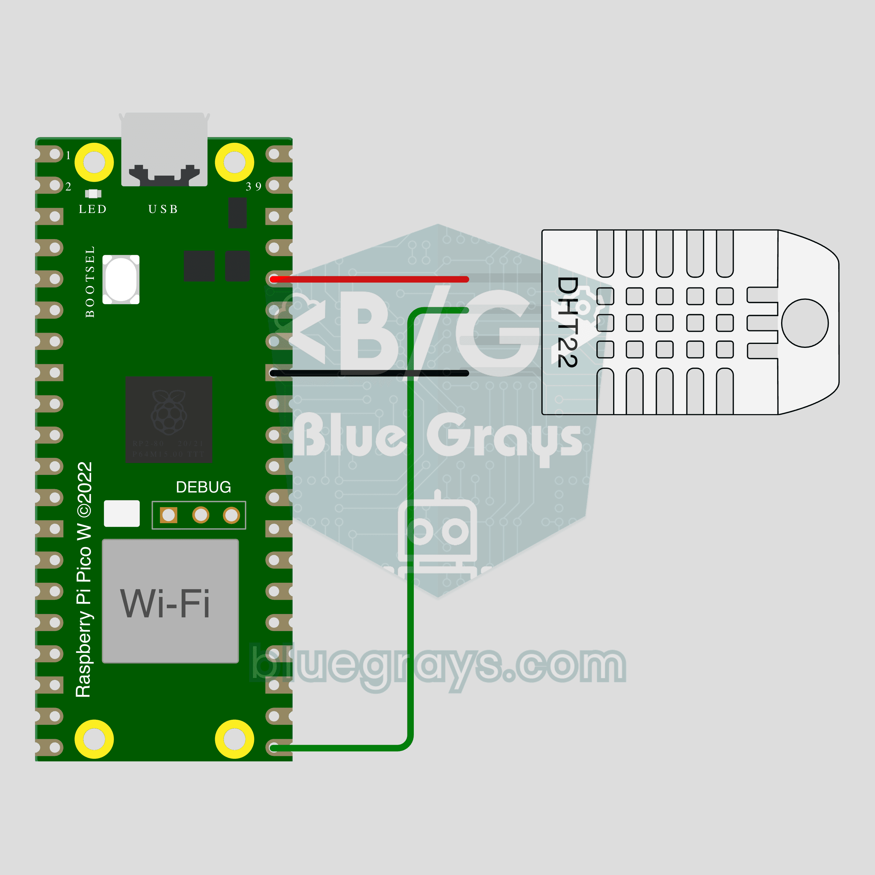
Pico W IoT Temperature and Humidity (DHT22)
Watch your room's temperature and humidity live on your phone wherever you are. This project is the step-by-step guide to the Temperature and humidity IoT template in the app, built with a Raspberry Pi Pico W and a DHT22. Go to Workshop › Devices › Add a device, pick Pico W as the board and Temperature and humidity as the template; Ohmi prepares the code with your own device key. The code on this page is an example: the key and Wi-Fi details are placeholders.
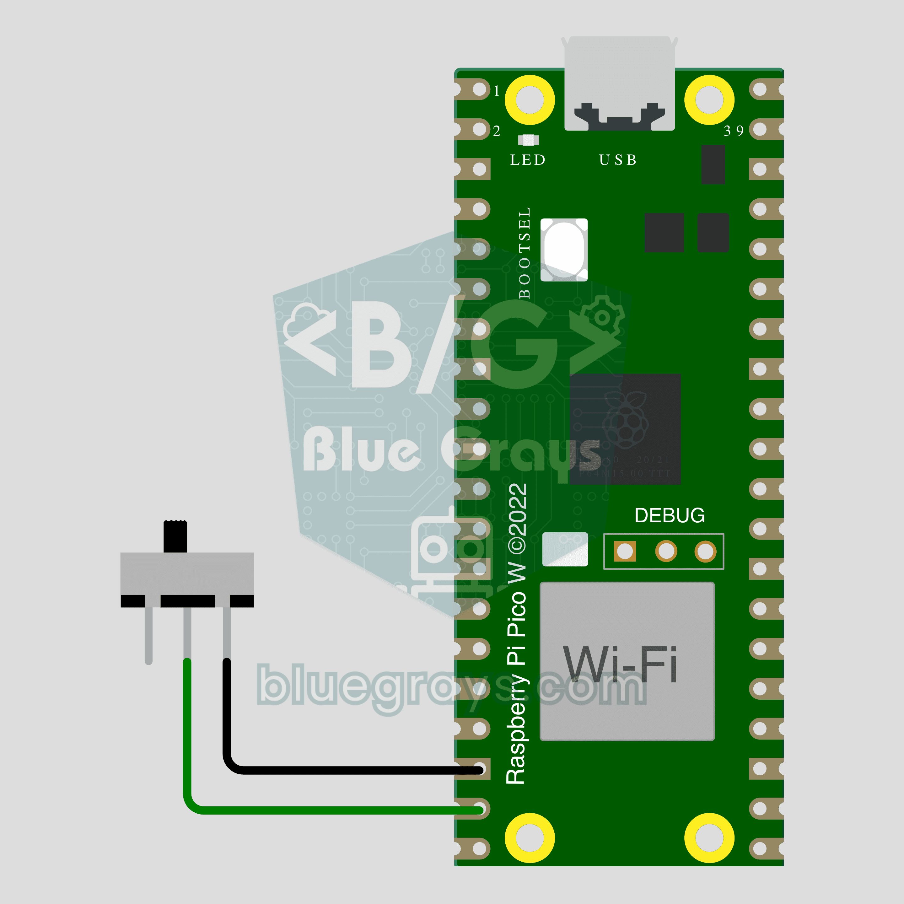
Pico W IoT Door Sensor (Reed Switch)
Did you leave the door or window open? Check on your phone wherever you are. This project is the step-by-step guide to the Door / window IoT template in the app, built with a Raspberry Pi Pico W, a reed switch and a small magnet using two wires. Go to Workshop › Devices › Add a device, pick Pico W as the board and Door / window as the template; Ohmi prepares the code with your own device key. The code on this page is an example: the key and Wi-Fi details are placeholders.
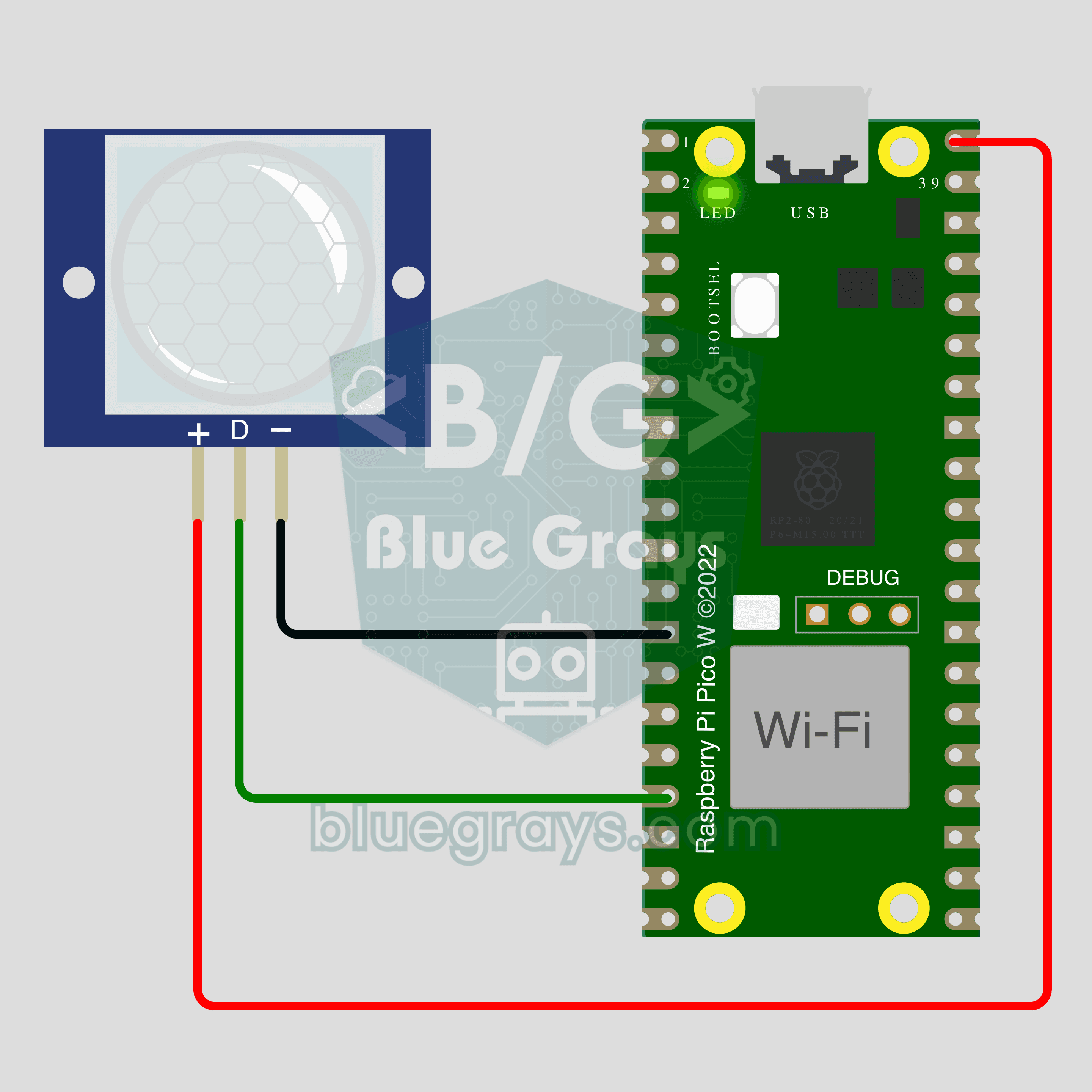
Pico W IoT Motion Counter (PIR)
Count how many times someone walks through a door or hallway, and see the moment of motion live on your phone. This project is the step-by-step guide to the Motion detector IoT template in the app, built with a Raspberry Pi Pico W and a PIR motion sensor using just 3 wires. Go to Workshop › Devices › Add a device; Ohmi prepares the code with your own device key. The code on this page is an example: the key and Wi-Fi details are placeholders.